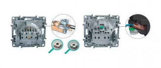
Requirements
The cable and attachments of the portable device must withstand short circuit current and dynamic loads. The clamps provide reliable contact and are heat resistant. The core cross-section for installations up to 1000 Volts is not less than 16 mm. Above 1000 volts, the conductors are at least 25 mm.
At voltages above 6 kV, the cross-section of the core will be 120 mm or higher, which is not practical and heavy. Therefore, it is allowed to install several grounding connections side by side, totaling the required cross-section.
It is prohibited to use an insulated wire for grounding conductors, since the insulating layer makes it difficult to detect damage to the conductor conductors and a reduction in the design cross-section in a timely manner, which can lead to burnout of the grounding conductor.
Device
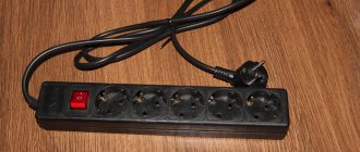
The manufacture of portable grounding occurs from a flexible cable, which is made of copper. There will also be special fastenings such as clamps with insulating handles. These devices are intended for phase abutment and connection to the grounding bus. Portable grounding can also be connected to a three-phase network. Below you can see a photo of portable grounding.
The design of the clamps allows for fastening using an insulated rod. In a three-phase grounding system, the cores will be connected using crimping or welding. It will also be possible to use a bolted connection if necessary. It is not recommended to use soldering, since in this case, as a result of a short circuit, the soldering points may heat up and destroy the integrity of the device.
You can see the portable ground electrode clearly and how to install it in the video below:
Standards for grounding systems
Requirements for portable grounding are dictated by the following circumstances:
- Absolute dynamic strength. The reliability of the clamps must meet standards so as not to break in the hands of electricians.
- Heat resistance. This requirement is dictated by thermal effects on grounding resulting from short circuits. The design must be resistant to burning, melting, and deformation from overheating at very high temperatures. The consequence of the lack of thermal stability will be high voltage at the burnt ends.
Conductor cross-section
In order to comply with mechanical strength parameters, the smallest cross-section of conductors should be:
- For electrical installations with voltages over 1000 V - 25 square millimeters.
- For electrical installations with voltages less than 1000 V - 16 square millimeters.
Smaller sections are not allowed by regulations. For electrical installations with voltages from 6 to 10 kW and high short-circuit currents, conductors with extra-large cross-sections (from 120 to 185 square millimeters) cannot be avoided. It is very difficult to work with such sections, and therefore in such situations it is possible to use several portable grounding conductors, which are placed parallel in close proximity to each other.
To calculate the required cross-section of conductors, the formula is used:
S = (Iutkz √tph) / 272,
Where:
- Iutkz – steady-state short-circuit current;
- tf – fictitious time in seconds.
The indicator tf can be considered identical to the time delay of the main protection of the relay connecting an electrical installation. The installation switch must stop a short circuit at the portable grounding site. It is necessary to avoid situations where it is necessary to make groundings of different sections for switchgears of the same voltage, therefore the largest indicator is taken as the time delay.
If the network has a grounded neutral, the conductor cross-section is selected based on the single-phase short circuit current. But in the case of an insulated neutral, high thermal stability during a two-phase circuit will be required.
The requirements for portable grounding exclude the possibility of using insulated wiring, since the insulating layer prevents the visual detection of defects in the conductor cores. As a result of damage, the cross-section becomes smaller, and this can cause a short circuit.
The design capabilities of the clamps must ensure their strong fixation on conductive elements using a special rod device. The shorting wires are connected to the terminals directly - without adapters. This standard is due to the fact that adapter tips may contain low-quality contacts. Such contacts are difficult to see, but if shorted, they are susceptible to fire.
The short-circuiting wires of a three-phase grounding conductor are connected to each other and the grounding conductor using crimping or welding. The connection can also be made with bolts, but in this case additional processing will be required - solder connection. Moreover, the solder must be hard, since soldering is prohibited for the reason that heating the device during operation will lead to melting of the solder and destruction of the connection.
It should also be said about what requirements are established for the marking of portable grounding devices. All devices must indicate the rated voltage of the electrical installation, cross-section of conductors and inventory number.
Requirements for overlay areas
According to technical rules, installation of portable grounding switches is carried out on all phase elements of the area disconnected from the electrical supply. Power is switched off at all connection points from which voltage may be supplied. In this case, the reverse transformation should also be taken into account. One grounding connection must be on each side - this condition is dictated by safety requirements. The area can be protected from live elements with disconnectors, switches or circuit breakers. You can also remove fuses for this purpose.
A clear break is required between the overlap areas to separate the devices from the live elements carrying voltage. The distance between live parts must comply with safety standards.
Portable grounding in closed-type distribution systems is installed on current-carrying elements. Areas specifically designed for grounding installation are selected. The paint layer is removed from such places, and the outline is highlighted with black stripes.
Important! Areas cleared of paint must be equipped with places for installing a clamp or have clamps.
If, for technical reasons, portable grounding cannot be installed in an electrical installation, additional measures will be needed to increase operational safety. To avoid accidental transmission of voltage, it is necessary to protect the upper contacts or blades with rigid insulation or rubber gaskets.
Removal - portable grounding
Removing the portable grounding should be done in the reverse order: first it is disconnected from the live parts, and then from the grounding wiring.
Removal of portable grounding should be done in the reverse order: first it is disconnected from live parts, and then from the grounding wiring.
The procedure for removing portable grounding connections is reversed - first disconnect the phase ends, and then the grounding end, also using protective equipment.
| Installation of portable grounding. |
When removing a portable grounding, on the contrary, it is first disconnected from the tires and wires, and then from the grounding device. This order is due to the fact that busbars, electrical machines, apparatus, and especially overhead and cable lines, after removing the voltage, can retain an electric charge for some time.
| A device on a rod for simultaneously checking the absence of voltage and applying grounding to overhead line wires on wooden supports. |
When removing portable grounding connections, first remove the clamps from live parts, then disconnect the grounding wire. All operations on applying and removing portable groundings must be performed using dielectric gloves.
The application and removal of portable groundings, the activation and disconnection of grounding knives must be reflected in the operational or pneumatic diagram, in the operational log and in the work order.
The application and removal of portable groundings must be carried out by two persons. All switching in the electrical circuits of the substation, indoor switchgear 6-10 kV and other electrical facilities of oil pipelines is carried out by order or with the knowledge of superior duty personnel.
The application and removal of portable groundings is carried out using dielectric gloves, c.
The application or removal of portable groundings, performed as a single operation or in combination with switchings for which no form is required, and carried out in the presence of an operating personnel with qualification group V, is carried out without switching forms with an entry in the operational log.
The application and removal of portable groundings must be carried out by two persons.
Installation and removal of portable grounding connections must be carried out wearing dielectric gloves and using an insulating rod in electrical installations with voltages above 1000 V. The portable grounding clamps should be secured with the same rod or directly with hands wearing dielectric gloves.
Installation and removal of portable grounding in electrical installations above 1000 V must be carried out wearing dielectric gloves using an insulating rod. The portable grounding clamps should be secured with the same rod or directly with hands wearing dielectric gloves.
Installation and removal of portable grounding must be carried out wearing dielectric gloves and using an insulating rod in electrical installations above 1000 V. The portable grounding clamps should be secured with the same rod or directly with hands wearing dielectric gloves.
Purpose of portable grounding
Portable grounding connections are intended to protect people working on disconnected live parts of equipment or electrical installations from electric shock in the event of an erroneous supply of voltage to the disconnected area or when induced voltage appears on it.
Portable grounding connections are used in those parts of the electrical installation that do not have stationary grounding blades.
The protective effect of portable grounding or stationary grounding blades lies in the fact that they do not allow a voltage dangerous for personnel to appear beyond the place of their installation.
When voltage is applied to a grounded and shorted section, a short circuit occurs. Thanks to this, the voltage at the point of the short circuit is reduced to almost zero and no voltage will flow to the current-carrying parts behind the grounding. In addition, the protection will work and turn off the voltage source.
What is it and why is it called temporary (portable)
The equipment is a type of protective device that ensures safe operation in connected electrical installations. In addition, portable grounding can (or rather, should) be used when performing work in the field: at temporary facilities that do not have a regular connection to the ground. For example, when carrying out welding work in an area where there is no power supply and the site is not equipped in accordance with the Electrical Installation Rules. In this case, both generating and operating equipment are grounded.
The temporary grounding kit is a set of flexible copper conductors (cable without insulation). At the ends of the conductors there are clamps with permanent fixation: like clamps.
Typically, the conductors are connected into three connected lines (for three-phase equipment). When the phases are shorted to each other, the likelihood of the protection tripping increases if voltage is accidentally applied to the line. Clamps that are connected to the power contacts are equipped with insulating rods (when working with voltages over 1000 volts). If during connection the bus is energized, electric shock will not occur.
There are also kits for single-phase electrical installations, consisting of one conductor with clamps at the ends.
Installation of portable grounding is provided in cases where the area taken out for repair is completely disconnected from any cable lines, including the “earth” bus. If voltage is accidentally applied (and during repairs this is quite possible), the device will provide a short circuit to the physical ground and trigger the circuit breaker.
Another function of portable grounding is protection against induced voltage. After de-energizing the electrical installation, induced currents may arise on the power cable from nearby power lines. In the normal state, this is prevented by the working “ground”.
What is portable grounding
Any types of grounding have the same purpose and belong to protective equipment. The portable type is used in temporary facilities where it is impossible to designate a permanent connection to the ground.
The temporary grounding kit includes flexible wires with permanent clamps at the ends. Typically, conductors are connected in three lines when connecting to three-phase installations. The tips must have insulated rods, since work can be carried out at voltages above 1000 V. This ensures safety if the busbar is live. There are also models for single-phase equipment. They have one conductor with a clamp at the end.
The use of portable grounding is dangerous without protective equipment in the form of circuit breakers and fuses. This is due to the fact that a short circuit may cause the power cable to catch fire.
Grounding of a transformer substation
As you know, transformer transformers are used to receive and convert voltage, as well as to distribute electricity in the electrical system. In view of this, the fact that ensuring the safety of technological processes is becoming an extremely important task is not subject to discussion.
When designing the installation of all transformer substations, an external and internal grounding loop must be provided.
The busbars must be routed along all walls, and then connected to the busbars in all adjacent rooms. These actions are necessary due to the need to protect all metal parts of the transformer substations without exception, even those that are not conductive.
The installation process can be divided into the following stages:
- The first stage is marking the route for laying the grounding.
- The second is preparation. A hammer drill makes holes for installing tires through walls and other mounting holes. They are equipped with metal sleeves of the required diameter.
- The third stage is the direct installation of grounding. The wires are secured around the perimeter using dowels. The wires themselves are connected directly to the grounded structures using welding or bolts.
Installation of portable grounding
Before starting work, you need to make sure that there is no current in this electrical network. According to the installation data, this production should be carried out by specialists of at least two people. Before starting work, it is necessary to check the presence of voltage. All work is carried out strictly with dielectric gloves, using a special rod. This production includes the following stages:
- connect the grounding conductor to the wiring that is grounded;
- use a special device to check the presence of voltage in the current-carrying part;
- throw the terminals one by one using a rod onto the current-carrying elements that need to be disconnected during this work;
- secure the clamps also with a rod;
- if for some reason it is impossible to carry out this work using a rod, then this is done with hands wearing dielectric gloves and only in areas with a voltage of no more than 1000 volts.
- the creation of grounding occurs in a standing position on the ground or on a ladder made of wood or other material that relieves voltage;
- it is very dangerous and it is prohibited to climb structures until the voltage is checked;
- in order to remove portable grounding, you need to do the same steps only in the opposite direction: disconnect the terminals from the current-carrying elements, then disconnect them from the grounding devices.
Rejection of portable groundings
When carrying out electrical installation work, any person responsible for their organization must know in which cases portable grounding connections should be removed from use. In this case, one should be guided by the main provisions of the working document entitled “ Instructions
for the use and testing equipment ”,
abbreviated as IPISZ (see paragraph 2.17.16). According to this regulatory document, during the operation of portable groundings, they are subject to mandatory visual inspection, carried out at least once every 3 months.
Important! Such inspections are also mandatory immediately before applying a protection order and immediately after exposure to short-circuit currents.
The portable grounding kit must be immediately removed from use in the following cases:
- If clearly visible mechanical damage and serious defects are detected on the elements of contact connections.
- If more than 5% of copper conductors are broken.
- In a situation where individual parts of the connectors have completely melted.
After discarding, the decommissioned set of PZs must be disposed of.
Electrical safety requirements when servicing the installation
The official safety rules for electrical safety describe provisions that affect the safety of work when working with operating units and live lines.
Only a qualified specialist with the appropriate level of clearance can work with electrical installations. According to the rules, if the voltage in the network is more than 1 kilovolt, activities can only be carried out if the foreman has a 4th degree clearance. His subordinates can take part if they have level 3.
In accordance with electrical safety rules, only a special team, which includes a holder of the 4th degree of clearance, can inspect damaged electrical installations. The safety rules say that the following should be located at a remote distance from high-voltage objects:
- Other people who are not part of the operational team.
- Hydraulic lifts.
- Telescopic towers.
- Automotive technology.
- Ladders, stepladders, cranes.
Security ensures that no one approaches a dangerous object without permission.
An ordinary worker can approach the unit only with the permission of the senior operating team and accompanied by him.
In substations with electrical equipment with a power of 1000 volts or more, a protective fence must be present. You can only be at the site and approach the equipment if accompanied by an authorized employee with electrical safety clearance. It is strictly prohibited to penetrate the fence.
Safety precautions when working on operating electrical units
All activities at operating electrical units must be documented on a special form. It states:
- Minimum amount of work performed.
- Venue.
- Date and time of the start and end of the assignment.
- A list of employees.
- Full name of the foreman.
All actions are performed only with the permission of management. They issue an order that specifies the algorithm and rules for performing the entire operation. It is prohibited to independently add or remove any items from it.
Important! All workers must be wearing a special uniform. It should have long sleeves and rubberized elements
It is prohibited to use metal tools without rubber protection that complies with GOST.
Working conditions:
- Hazardous elements must be located directly in front of the worker's face.
- Lighting should be acceptable, not too intense.
- It is prohibited to work outside in rainy weather.
Measures for safe work performance
To reduce the likelihood of negligence and improve safety, management should:
- Document all activities in the form of orders, orders and lists.
- Monitor the standard of order in the work area.
- Make sure that only authorized persons are allowed into electrical installations.
- Provide full command to the foreman for assistance.
- Officially record the beginning and end of the task, the transition to another object.
Safety precautions when working
Employees are responsible for compliance with safety regulations when operating consumer electrical installations in the same way as managers.
Requirements for portable grounding
The main requirement for portable groundings is their thermal and dynamic resistance to short circuit current. The clamps with which conductors are secured to live parts must be such that they cannot be torn off by dynamic forces. In addition, the clamps must provide very reliable contact. Otherwise, if there is a short circuit, they will overheat and burn.
When short-circuit current flows, the short-circuiting conductors become very hot. Therefore, they must be sufficiently thermally stable to remain intact during the tripping time of the short-circuit protection relay. It must be borne in mind that copper melts at a temperature of 1083 ° C. The thermal stability of conductors is important, because when the conductors are heated and broken, the operating voltage of the electrical installation may appear at their ends. The minimum cross-section for reasons of mechanical strength is accepted: for electrical installations with voltages above 1000 V - 25 mm2 and for electrical installations with voltages below 1000 V - 16 mm2. Conductors smaller than these cross-sections cannot be used. For electrical installations with a voltage of 6 - 10 kV with significant short circuit currents, portable grounding conductors are of a very large cross-section (120 - 185 mm2), heavy and difficult to use. In such cases, it is allowed to use two or more portable grounding connections, installing them in parallel, one directly next to the other.
Sections of grounding conductors in electrical installations above 1000 V
| Grounding conductor cross-section, mm2 | Maximum permissible short-circuit current, kA with duration of main relay protection, s | ||
| 0,5 | 1,0 | 3,0 | |
| 25 | 10 | 7 | 4 |
| 50 | 20 | 14 | 8 |
| 70 | 25 | 18 | 10 |
| 90 | 35 | 25 | 15 |
| 2x50 | 40 | 28 | 16 |
| 2x95 | 70 | 50 | 30 |
The cross-section of portable grounding conductors is calculated using a simplified formula:
S = (Iset √tph) / 272,
where Ist is the steady-state short-circuit current, A,
tf — fictitious time, sec.
For practical purposes, the value of tf can be taken equal to the time delay of the main relay protection of the connection of the electrical installation, the switch of which must disconnect the short circuit at the portable grounding point. In order not to make portable grounding connections of different cross-sections for switchgear of the same voltage, the longest one is usually taken as the design time delay.
In networks with a grounded neutral, the cross-section of the conductors is calculated based on the single-phase short circuit current, while in a system with an isolated neutral, it is sufficient to ensure thermal stability during a two-phase short circuit. It is not allowed to use insulated wire for grounding conductors, because insulation does not allow timely detection of damage to the conductor cores, which reduces its design cross-section and can lead to flashover by short circuit current.
Portable grounding
The design of the clamps for connecting conductors must ensure the possibility of their reliable and durable fastening to live parts using a special rod for installing grounding. The short-circuiting conductors are connected directly to the terminals without adapter lugs. This requirement is explained by the fact that the tips may contain unsatisfactory contacts that are difficult to detect, but which may burn out when a short circuit current flows. The connection of the three-phase grounding short-circuiting conductors to each other and to the grounding conductor is carried out firmly and reliably by crimping or welding. A bolted connection can also be made, but in addition to the bolts, the connection must be soldered with hard solder. Connection by soldering alone is not allowed, since the heating of the groundings during the flow of current can reach hundreds of degrees, at which point the solder will melt and the connection will be broken.
Portable grounding device
Portable grounding connections consist of: conductors for grounding and short-circuiting between themselves current-carrying parts of different phases of an electrical installation and clamps for connecting conductors to the grounding wiring and to live parts.
Grounding and short-circuiting conductors are made of copper stranded flexible bare wire.
Portable groundings are carried out both three-phase (for short-circuiting all three phases and grounding with a common grounding conductor) and single-phase (for grounding the current-carrying parts of each phase separately). Single-phase portable grounding connections are used in electrical installations with voltages above 110 kV, since there the distances between phases are large and the short-circuiting conductors are excessively long and heavy.
Related links
- Rules for the technical operation of consumer electrical installations / Regulatory document dated February 9, 2007 at 02:14
- Electrician's Bible / Regulatory document January 14, 2014 at 12:32 pm
- Handbook on electrical networks 0.4-35 kV and 110-1150 kV. Volume 10 / Regulatory document from March 2, 2009 at 18:12
- Kabyshev A.V., Tarasov E.V. Low-voltage circuit breakers / Regulatory document dated October 1, 2021 at 09:22
- Rules for the installation of overhead power lines with voltage up to 1 kV with self-supporting insulated wires / Regulatory document dated April 30, 2008 at 15:00
- Mankov V.D. Zagranichny S.F. Protective grounding and grounding of electrical installations / Regulatory document dated March 27, 2021 at 09:05
- Knyazevsky B.A. Trunkovsky L.E. Installation and operation of industrial electrical installations / Regulatory document dated October 17, 2019 at 12:36
Portable grounding up to 1000 volts
For these types of grounding, grounding conductors with conductors with a cross-section of 16 sq. mm are provided. These brands include:
- PZRU-1 is designed to protect workers who work on live parts of electrical installations with voltages from 0.4 - 1 kV. Solid duralumin grade D16 is used. The terminals are in good contact with the wires and have a simple design; they can also be applied to inclined wires. In this case, the conductors are highly flexible, copper, stranded, transparent PVC insulation. The device also has a steel spring, which is located between the wire and the terminals, thereby preventing damage. The design has a specially selected rod that matches the size.
- ZPL-1 – portable grounding for overhead lines up to 1 kV. The cross-section of conductors in this type can be from 35-95 sq. mm, in single-phase or three-phase versions. This device is also equipped with a rod that is coated with powder paint and a tube that protects against thermal effects.
- ZPP-1 – for distribution devices. This design is of a three-phase type with three rods, the cable cross-section varies from 25-95 sq. mm. The terminals are made of aluminum, attached to the wire using copper sleeves.
Components of portable grounding
The portable grounding kit contains three main elements:
- conductive element;
- contact;
- an insulating layer or several insulators at once.
According to design features, portable systems are divided into:
- rodless;
- rod;
- rod with metal components.
Rodless systems consist of the following parts:
- conductive element (flexible wire);
- contact element (clamps, phase clamps along with fasteners);
- insulation made from a flexible supporting and controlling cord.
Operating insulating rods and portable grounding rods include:
- conductive element (flexible wire);
- phase contact clamps, lugs, clamps;
- insulation made from dielectric.
The picture above shows a rod grounding diagram, where the numbers indicate its elements:
- Phase clamps.
- Barbells.
- Shorting wire.
- Grounding wire.
- Clamps.
The structural parts of a grounding system with metal rod components are:
- conductive element with metal components (joins with flexible wire);
- a contact clamp attached to a clamp with a metal link;
- a dielectric insulator rod connected to a conductive element and halyards.
Protection devices with one and three phases are available on the market. Three-phase systems have a single grounding conductor and provide a shorting and grounding function for three phases. Single-phase protection is designed to protect workers employed in electrical installations with voltages above 110 kW. This approach is due to the fact that if there are several phases between them, a certain distance is necessary, and this leads to unnecessary bulkiness of the structure.
The picture above shows portable grounding with the presence of electrodynamic knives. The numbers indicate the following elements:
- Ground wire.
- Shorting wire.
- Clamps.
- Knives.
- Dielectric rods.
Note! One application of portable systems is to protect workers repairing overhead lines and electrical distribution installations.
Grounding for fire equipment
Fire trucks are protected by portable grounding systems, which allow them to work in conditions where conductive parts of the equipment are exposed to water jets. Portable grounding for fire trucks includes:
- grounding conductor (crimped flexible copper wire in a transparent sheath);
- tips;
- clamps.
The ends are bolted to the clamp on one side and to the fire truck barrel on the other.
Grounding for overhead lines
To prevent electric shock to people during electrical installation work on overhead lines, two types of single-phase and three-phase grounding are used:
- Systems equipped with a one-piece insulator rod. Such devices are installed from assembly towers. Also, mounting claws and manholes can be used to climb up.
- Portable type grounding switches with a composite rod containing conductive metal elements. The use of such devices occurs in the case of repair work on high-voltage power lines, in cases where work is carried out from traverses. Grounding electrodes are produced in single-phase configurations, since the extended rod coupled with metal parts weighs too much. But single-phase modifications are convenient to use, as they do not force electricians to physically overload.
Protection on distribution equipment
When voltage is induced from neighboring circuits or voltage is involuntarily directed to switchgear, electric shock may occur. In such cases, portable grounding electrodes are used, which may differ in installation methods in distribution devices. Installation of phase clamps is carried out on tips in the form of balls or cylinders, on conductive busbars, as well as on areas where fuses are located . All types of devices are identical in design, and the location for installation work is selected based on the assigned tasks and characteristics of a particular installation.
Ticket number 11
1. HOW IS THE ASSIGNMENT OF GROUP I FOR ELECTRICAL SAFETY TO NON-ELECTRICAL TECHNICAL PERSONNEL ASSIGNED? /1, clause 1.4.4/
2. WHAT ARE THE TIME TERMS FOR THE NEXT KNOWLEDGE CHECK OF ELECTRICAL AND TECHNICAL PERSONNEL SERVICING OPERATING ELECTRICAL INSTALLATIONS? /1, clause 1.4.20/
3. WHAT VOLTAGE SHOULD BE USED TO POWER PORTABLE (MANUAL) ELECTRIC LAMPS IN PARTICULARLY HAZARDOUS PREMISES? /1, clause 2.12.6/
4. HOW IS THE PROCEDURE FOR STORING AND ISSUING ELECTRICAL INSTALLATION KEYS DETERMINED? /2, clause 3.13/
5. AT WHAT SUSPENSION HEIGHT OF LUMINAIRES IS THEIR SERVICING FROM OVERHEAD CRANES, FIXED BRIDGES ALLOWED? /1, clause 2.12.14/
6. WHAT SHOULD BE THE DURATION OF FORCED VENTILATION BEFORE STARTING WORK IN UNDERGROUND CABLE STRUCTURES? /2, paragraph 37.37/
7. WHAT IS THE PROCEDURE FOR INSTALLING PORTABLE EARTHINGS? /2, clause 20.2/
8. WHAT ROOMS ARE ELECTRICAL ROOMS? /3, clause 1.1.5/
9. WHAT IS THE MINIMUM SECTION OF WIRES WITH COPPER CONDUCTORS SHOULD BE USED FOR CHARGING STATIONARY LIGHTING FIXTURES FOR LOCAL LIGHTING FOR MOVABLE STRUCTURES? /3, clause 6.6.18/
10. CAN DIELECTRIC CARPETS BE USED IN OPEN ELECTRICAL INSTALLATIONS? /4, clause 2.12.1/
Go to result
Related Posts
- Concept and operating principle of protective grounding
- Gzsh. main ground bus
- Why is the grounding system TT (to its circuit) more dangerous than tn (to neutral)
- How to check grounding
- Features of the use of zero buses
- Protective conductors (PE conductors)
- Safety guarantee, or how to properly ground in a private home
- Grounding pue
- Where to get grounding in Khrushchev
- What color is phase and zero in electrical engineering?
- Using PVC wire according to the characteristics and description
- How to connect grounding in the panel. how to do grounding correctly in an apartment or private house
- Features of shdup u4
- Corrugated sheet dimensions: length, width, height, thickness
- Pugnp and punp wires: characteristics, differences, prohibition of use
- Wire cross-section for home wiring: how to calculate correctly
- Review of effective methods and types of neutral grounding
- What are phase, neutral and grounding for?
- Why does a water heater shock and what to do?
- Methods of personal protection against electric shock
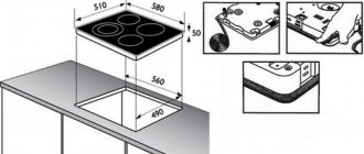
- Connecting the hob to the electrical network: diagrams, selection of cables, sockets, machines
- Hidden electrical wiring in a frame house
- Three-phase circuit breaker c25
- Ouzo in electrics
- Wiring diagram and installation of electrical wiring in the kitchen
Read with this
- Concept and operating principle of protective grounding
- Gzsh. main ground bus
- Why is the grounding system TT (to its circuit) more dangerous than tn (to neutral)
- How to check grounding
- Features of the use of zero buses
- Protective conductors (PE conductors)
- Safety guarantee, or how to properly ground in a private home
- Grounding pue
- Where to get grounding in Khrushchev
- What color is phase and zero in electrical engineering?