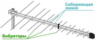
Description of antenna operation
The antenna for the radio is part of the wireless search for radio and television signals, messages through the navigation system of geographic coordinates and vehicle speed. The devices are used to convert electromagnetic waves into an electrical signal, which is amplified by the receiving antenna housing. Important characteristics of the device include the satellite signal reception distance, bandwidth, and number of channels.
The operating principle of the device is to determine and transfer signals from satellites to the car after processing and conversion to an intermediate frequency. The conductor is connected to the on-board equipment of the machine.
The device provides continuous and high-quality signals to the car radio and video recorder.
The device is designed to be combined into a single system with video cameras, navigation, and parking sensors to solve complex problems for the driver of a vehicle.
The advantages of the device are compactness, ergonomics, versatility, easy installation, and long service life.
Message formats
GPS data is displayed in different formats via a serial interface. There are standard and non-standard (proprietary) message formats. Almost all GPS receivers output NMEA data. This is a standard for formatting information in strings called sentences. Each one contains different data separated by commas. There are 19 types of such offers in total. Here is an example of an NMEA string received from a receiver that has established communication with a satellite:
The proposal contains the following information:
- GMT time: 23:53:17;
- latitude: north, 40.039039°;
- longitude: west, 10.5125793°;
- number of satellites: 08;
- altitude: 1577 m.
The data is separated by commas to make it easier to read and analyze by computers and microcontrollers. They are sent to the serial port at an interval called the update rate. Most receivers update this information once per second (i.e., at a rate of 1 Hz), but the best GPS receivers are capable of multiple updates per second. For modern models this value is 5–20 Hz.
Classification
GPS antennas for car radios are divided into:
- external;
- internal.
External devices are designed to search for radio and television signals. The device is highly sensitive and is mounted on the outside of the machine. It is necessary to take into account the exposure of the device to precipitation and changes in temperature conditions. The equipment is equipped with an adapter that increases the search parameters for radio frequencies. External devices are attached to the body, trunk, roof, bumper or fenders of the car.
In-cabin devices are mounted on the windshield of a car. The equipment is equipped with amplifiers inside the housing. The device is universal, suitable for different types of car radios, does not require complex installation work, but is very expensive.
Devices are divided into passive and active.
An active GPS antenna is a standard device, the system of which is supplemented by an internal signal amplifier. The devices are sensitive, accurately and quickly detect a large number of radio and television waves. The device reduces the amount of interference and noise when playing music and videos.
The functionality of a passive type device depends on the volume of electromagnetic radiation in the area. If there is a small amount of interference, the reception of the radio signal will be stable, but if there are electrical appliances within the range (in cities), the reception accuracy will decrease.
By type of design, devices are divided into:
- asymmetrical;
- dipole.
A device with an asymmetrical housing is mounted perpendicular to the plane of radio frequency propagation. The equipment is equipped with a telescopic structure, consisting of parts that are unfolded manually or using an electric drive. The antenna includes a pin equipped with a spiral at the base.
Dipole devices are equipped with 2 rods located symmetrically. The devices are mounted in a horizontal position. The type of equipment is optimal for placement inside the car.
How to make an outdoor amplifier yourself
Knowing your own location is important in some cases, which is why navigation is increasingly becoming part of everyday life. Very often, users are faced with a weak GPS signal when it is needed, or even its complete absence. A way out of this situation could be a self-made antenna for any device with a GPS module.
A device of Chinese origin with a GPS module often suffers from a lack of signal; The reason is a weak signal receiving module. The antenna is operated by a patch located on the outside of the device. It should be noted that this device works outdoors, but the signal disappears if poor reception conditions are created (bring the device into the house, put it in the car). Procedure:
- We determine how difficult or easy it is to get to the GPS module;
- We take copper wire with a cross section of 5/2 millimeters square, a length of 46 millimeters * 4, where 4 are the sides of the square, it represents a square;
- We make a regular square from the wire, use pliers, we need to keep the dimensions exactly, how the antenna will work depends on this;
- Solder the antenna to the external GPS patch.
For convenience, the antenna can be attached to the device body with tape. The result of the work performed is stable signal reception by the device indoors and in the car.
An example of a homemade GPS antenna makes it possible to receive a signal even in bad weather conditions and inside the car. Travel enthusiasts often use navigation when they need to plot a short route from one point to another. An outdoor GPS antenna guarantees stable signal reception.
Adapters
An antenna adapter is used when replacing a car radio with a product of a different brand. The device allows you to reduce the difference in settings and design solutions, and also enhances the quality of searching for radio frequencies.
According to experts, purchasing an adapter is necessary:
- when the sound quality decreases, there is interference, noise, distortion in the played video and audio recordings;
- when the number of received radio stations decreases;
- when the signal in the device periodically disappears;
- when the picture on the screen of the radio or video playback device is blurry.
When selecting an adapter for a machine, you must consider:
- uniform amplitude-frequency indicators of the adapter;
- the presence of a gain of about 15-25 dB;
- sufficient height of dynamic range;
- presence of low noise figure and high gain.
The designs and dimensions of adapters for passenger cars and trucks may differ.
How to properly install a GPS antenna in a car
Before installation, it is important to determine the optimal location for the antenna. Experts recommend placing the devices on the roof of the car or on other surfaces of the equipment. An antenna located perpendicularly encounters less interference and transmits the signal quickly. It is optimal to place the device under the roof, on the top of the windshield of the car.
The signal from the device on the rear window or in the lower block of the windshield arrives with less intensity, but the device will be preserved better. It is not recommended to place the device near lamps, because reception quality will decrease due to electromagnetic radiation.
The structure is attached in several ways:
- magnetic;
- overhead (with a clamp);
- mortise;
- internal.
The magnetic method allows you to fix the device in different parts of the machine. The mount has a budget price, simple installation, does not require openings in the body of the equipment during installation, and reduces the risk of deformation. However, it is necessary to remove the device in parking lots to prevent theft. It is important to take into account the short length of the receiving dipole, which makes it difficult to determine signals in desert areas.
The overhead mount allows you to install the device on the car body using brackets and threaded connections. The device is attached to the rear bumper or drain of the car. An amplifier is not provided in antennas with a surface-mounted type of fastener; it is necessary to take into account the compatibility of the product with the design of the machine.
The mortise antenna is mounted through a hole in the car body (front or rear fender). The opening is treated with a composition that prevents corrosion. The method allows you to hide the mounting pin. It is necessary to regularly process the hole and monitor the integrity of the structure.
Internal installation of the technical device is recommended for GPS modules. The device is placed on the top of the windshield; the surfaces are treated with a special compound before installation. The devices require connection to a satellite signal amplifier and a dedicated power source. The interior antenna is equipped with adjustable gain intensity, does not create noise, does not require complex maintenance and reconstruction of the machine, and has no risk of deformation during operation.
Housing Antennas
Designed for external use or replacement/installation in ready-made GPS devices. Wi-Sys produces a range of antennas in this category: with a magnetic base for easy installation on metal surfaces; the radial type for pin mounting (which is actually a hollow tube with an external thread inside which the coaxial cable runs) and patch antennas for surface mounting. In the first category, three series of antennas are offered, optimized in terms of minimum noise, low power consumption and low price. The antennas differ only in price and technical characteristics, but the appearance of these three series is the same. WS3910 series of antennas (Fig. 12) represents specially designed antennas based on ceramic elements, which made it possible to reduce the detuning effect caused by objects surrounding the antenna.
Rice. 12. Appearance of the Wi-Sys WS3910 antenna
The antenna has excellent parameters and is very convenient to install: it not only has a magnetic base, which greatly simplifies installation at the site of operation, but also holes located in the lower part, which also make it possible to mount it with screws. At the same time, the weight of the antenna is 120 g, and the overall dimensions are only 45x51x12 mm. The operating temperature range is quite wide and covers permissible values in the range from –40 to +80 C. The antenna belongs to the low-noise class, therefore the total noise figure of the signal received from the antenna for this model does not exceed 0.8 dB. At the same time, the low-noise amplifier provides excellent gain: 28 dB at a voltage of 3.3 V (current consumption does not exceed 7.5 mA) and 28.5 dB at a supply voltage of 5.0 V (current consumption 11.5 mA). Like all previously discussed antennas, this model has an impedance of 50 Ohms. The manufacturer recommends ordering the antenna equipped with a coaxial cable with an SMA connector, but upon request it can be supplied with SMB, SMC, MCX, BNC and TNC connectors. WS3914 series (appearance shown in Fig. 11) is optimized for use in low-power technology: current consumption at a supply voltage of 2.7 V does not exceed 2 mA. In this case, good electrical parameters are achieved, determined by the LNA used: it provides a gain of 18 dB and noise of no more than 1 dB (at a voltage of 3.3 V). The permissible supply voltage range is from 2.5 to 3.3 V. The antenna comes with the same types of connectors as the WS3910. Another representative of the category of antennas with a magnetic base is the WS3917 , the optimization criterion for which is price. It has good electrical parameters at a low cost: supply voltage is 2.7–5.0 V, while the LNA provides a gain of 28 dB and a noise figure of no more than 1.5 dB. The current consumed by the active part of the antenna is significantly higher than that of the WS3914 model, but the price reduction comes at the price of higher power consumption: with a supply voltage of 3.3 V, the antenna amplifier consumes a current of 9.0 mA, and with a voltage of 5.0 V - 15.0 mA , and the range of permissible supply voltage is much wider: 2.7–5.0 V. The connector types are similar to the WS3914 model, the antenna is supplied with a 3 m long coaxial cable, the loss of which is 1.3 dB/m, that is, complete attenuation in the cable reaches 3.9 dB, but the high gain of the LNA neutralizes this problem.
Rice. 13. Appearance of the Wi-Sys WS3977 antenna
Wi-Sys' hole-mount antenna category is represented by the WS3977 (Fig. 13). These antennas are characterized by extremely high suppression of out-of-band frequency components of the signal. The active part uses a modern element base using surfactant filters, which provides it with good electrical parameters. For ease of installation, the manufacturer also offers a special bracket for mounting on horizontal surfaces. Overall and mounting dimensions of the WS3977 antenna are shown in Fig. 14. The antenna is placed in a dust- and moisture-proof housing with a diameter of 66 mm and a height of 44.4 mm, while the total weight of the antenna is 50 g. The range of permissible supply voltages is extended - from 2.7 V to 5.0 V. The noise factor is no more than 1 .5 dB with a gain of 28 dB (3.3 V supply) and 30 dB (5.0 V supply). The antenna comes with a single type of connector - TNC.
Rice. 14. Overall and connection dimensions of the WS3977 antenna
Wi-Sys surface mount antennas are represented by the WS3977 (Fig. 15). The antennas are very compact (44.28 x 13.42 mm) and are discreet in use, while maintaining excellent technical characteristics when operating from a power source with an output voltage of 2.7–5.0 V.
Rice. 15. Appearance of the Wi-Sys WS3977 antenna
The method of mounting this antenna (with four M4x40 screws) can be easily understood from Fig. 16, which shows the overall and connecting dimensions necessary for its installation at the site of operation. The power consumption of the antenna is of the middle class and is 9 mA at the lower limit supply voltage and 15 mA at the upper limit, while the gain for the first mode is 28 dB, and for the second it exceeds 30 dB. Unlike previous models, the WS3977 antenna is not equipped with a cable, but has a built-in MCX connector, which in most cases is not a problem, but an advantage, since it provides greater flexibility and convenience than using antennas with a built-in cable.
Rice. 16. Overall and connection dimensions of the WS3977 antenna
An extended temperature range (–40… +85 ºС) and a sealed design allow the antenna to be used in difficult operating conditions without any problems. In addition, upon request, the antenna can be supplied in housings of various colors.
Operation setup and connection
After installing the GPS antenna, you need to connect and configure the device. Connects connections with external sources and control wire with marking code AMP-CON. The gray cable with the letter BRAKE regulates the disconnection from watching TV and DVD programs when the car is moving.
You can do the setup work yourself according to the instructions from the manufacturer, which contains software support for the model (OZI, Navitel, IGO). The necessary programs are recorded on the SD card. The IGO8 system requires setting the resolution for the radio to at least 480x234 px.
Then the map is inserted into the device, and the “Options” section is selected in the main GPS menu. In the settings, the required program is selected, the path to the SD card is indicated, and the navigation program is turned on. After testing the settings and operation of the device, the device will determine the location based on geographic coordinates and allow you to connect radio or video
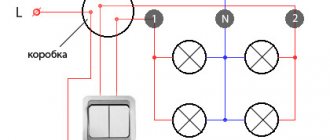
Connection options and diagrams
You can see the connection diagrams in the photo.
GPS antenna connection diagram.
The connection is made directly to the device or to a power source. The second option is more convenient if a person plans to use the navigator in a car.
The connection can be made by removing the multimedia system from the car radio. The cover is removed from the right side of the dashboard, the antenna connector is connected to the back of the radio, after which the device itself is secured with a magnet. The GPS must be positioned horizontally for it to work correctly. Then the dismantled elements are installed in the reverse order.
Possible problems and their solutions
When installing the device, interference may occur when receiving a signal in urban areas, mountainous areas, in dense traffic, etc. If there is no clear recognition of information, the sensor records inaccurate data or stops working.
Experts recommend changing the location of the antenna by installing the device on a window or roof. The type and quality of the vehicle must be taken into account. Some car models have tinted windows with metallic inclusions that block the radio signal.
DIY GPS antenna
GPS – antenna modernization.
GT-N7005 MTK6577 5.2″ 3G GPS 1G RAM TV 8.0MP Camera
OS and firmware:
Android 4.1.9 ALPS.ICS2.MP.V1
Description of the problem:
Why here? Because I'm a newbie. Now on topic. GPS doesn't work. Or rather it worked, but now it doesn’t. I wanted to do better, but it turned out as always. I assume that I installed the program FasterFixv92.apk. After installation, when I launched it, it didn’t work completely and gave an error. Then I launched YGPS. Three or four satellites were captured (transparent columns appeared). They stood there for a minute, and then one by one they disappeared.
Remove the outer back cover and remove the battery, I think this is understandable. Surely you have done this more than once.
1. Be sure to remove the SIM card and memory card. Not only for safety reasons, but also because they will prevent the inner cover from being removed. The telescopic antenna must be in transport condition, that is, folded (recessed). It doesn't interfere with disassembly. 2. Remove 6 (six) screws. One of them is located under a paper-type seal. If you want, it can be easily removed from there with a needle without damaging the appearance. And then put it back. 3. Now the interesting part is what scares everyone. Please note that the chrome rim is integral with the lid. Nothing more than a metallized part of a plastic cover. We place the device with the battery compartment down, having previously spread something soft, such as a clean towel, with the screen facing up. Whichever is more convenient for you. I held the phone in my palm. Next, I took a small knife with a thin and blunt blade and a rounded tip. We are trying to insert it between the chrome bezel and the screen. Along the perimeter we find the place where this is easiest. I got it in the area of the volume keys. We move the bezel to the side, lifting the screen and freeing it from the latches holding the cover from the rest of the structure. Don't make a big effort, just don't be fanatical. The latches are small and they are easily released from fixation. After going all the way around, release all the latches. After this, you may have to lightly press the inside of the battery compartment in the area of the SIM card. Actually, the battery compartment tray is attached to the back cover and should not interfere with your actions. PS: People recommend using a mediator for playing stringed musical instruments or a special knife for disassembling. That's it, the cover is off! Congratulations to you!
The length of the conductors is 10 cm each, the diameter of the wire is from 0.1 to 0.25 mm. The distance between the conductors is 8 – 9 mm. After soldering, we thread it through the hole for the standard antenna. We fix the conductors with tape on top of the cover, as indicated in the figure. There is no need to remove the standard antenna! After modification and closing the back cover, you may notice that the reception has deteriorated. This is due to the fact that parasitic capacitance is added to the input oscillatory circuit. What did I do to reduce this effect? The oscillatory circuit consists of capacitance “Sk” and inductance “Lk”. If we bring the brass to our antenna we will notice that the signal level changes. When the signal increases, we shorten the antenna (which is more likely to be the case with a length of 10 cm), and when it decreases, we increase it. If you use ferrite instead of brass, the picture will be the opposite. For me, the total length of each wire was about 7 cm. The diameter of the wire was 0.2 mm. By this we achieve resonance and, accordingly, reduce the influence of the back cover of the device. You will see for yourself where to solder, or look at my posts on this topic. For example, I did not solder on the gold-plated top part, so as not to interfere with the reliability of contact with the standard antenna.
Post edited by artem1701
– 02.05.16, 14:09
Perhaps someone has exactly the same device. As I wrote above, libmnlp was saved by me after the GPS stopped working. I'm not sure if my libmnlp file is intact. Comparing JY-G3's libmnlp with my libmnlp, there are differences in four lines of the file. Compared using Hex Workshop 4.2. I’ll say right away that I’m far from programming, I was just comparing files. Request to all forum members, if you have a native or similar libmnlp file, please reset it to me. Perhaps you can tell me where to look for it or have any ideas for restoring GPS.
Post edited by Benikolay
– 30.03.13, 09:16
I think it’s not enough, compare.
N7000+ MTK6577 Dual Core 5.3 Inch 800 x 480 Pixels Android 4.0 3G GPS TV SmartPhone
Basic information Model N7000+ 2G: GSM 850/900/1800/1900 MHz 3G: WCDMA 850/2100MHz TV
OS system Android 4.0.4 Processor MTK6577, Cortex A9 Dual Core, 1.0GHz 4GB ROM RAM 512MB
Screen Display size 5.3 inches Type TFT, capacitive touch screen Resolution 800 x 480 pixels
Supported formats Calls Type Polyphonic/MP3 Audio file formats MP3/WAV/AMR/AWB Video file formats 3GP/MPEG4 Image file format JPEG / BMP / GIF / PNG / GIF E-book Format TXT / CHM / DOC / HTML FM radio Yes, Headphones required Headphones 3.5mm port Card expansion Support TF memory card up to 16GB extended
Data transfer and connections Data transfer USB / Bluetooth Mobile Internet WAP / WIFI
General Camera / Photo Resolution Dual cameras, front camera: 0.3MP, rear camera: 8.0MP with flashlight, up to 3264×2448 pixels
Language English, Arabic, Russian, Serbian, Ukrainian, Persian, Hindi, Korean, Japanese, Simplified/Traditional Chinese
Message SMS/MMS Login Handwritten/Keyboard GPS Yes, built-in, also supports A-GPS WIFI Yes, 802.11 B/G Bluetooth Bluetooth 2.0 Gravity Sensor Yes Multi-Touch Yes, 5 touch points Other Features 3G, GPS, Play Store, WiFi , Bluetooth, E-reader, Email, Messaging, VPN Services, Wallpapers, Calendar, Calculator, Clock, Tethering & Portable Hotspot, Camera, etc.