According to the electrical standards of past decades, the ground loop in private homes was not a mandatory element of protection. The loads on the electrical networks were relatively small, and steel pipes coped well with current leakages.
However, over time, plastic and composite products began to be used instead of metal communications. In addition, a large number of electrical household appliances have appeared in country houses: air conditioners, heating equipment, powerful computer and refrigeration equipment.
As a result, grounding loops have become almost a prerequisite for organizing a powerful and safe electrical system in private homes. If you wish and have basic knowledge of electrical engineering, you can create a grounding loop with your own hands.
What is a ground loop
Grounding is the deliberate creation of an electrical connection to the ground of non-current-carrying elements of electrical installations. These pieces of equipment are not energized most of the time, but may become energized.
The ground loop performs the following functions:
- protects electrical equipment from power surges;
- protects residents from electric shock;
- resists “spreading” of electricity;
- used for lightning protection purposes.
As you know from a school physics course, current always propagates according to the principle of least resistance. In the event of a violation of the insulating layer on current-carrying elements, it quickly finds the area with the lowest resistance. As a result, a breakdown occurs on the body of the electrical appliance, which becomes energized.
The danger of this situation is not only in the disruption of the normal operation of equipment and the possible failure of devices, but also in the high probability of electric shock to a person. A grounding loop is designed to correct the situation, which distributes the current between a person and a grounding device in inverse proportion to their resistance.
Since the body resistance is much higher than the similar parameter of the grounding loop, only a small—non-dangerous—part of the current passes through a person, and the rest goes into the ground. Thus, when creating a ground loop, it is necessary to do everything in such a way as to achieve the lowest possible level of resistance.
Rules, regulations and basic requirements of the PUE
It's time to get acquainted with the basic requirements for grounding systems in private homes. The main parameter is the loop resistance, which determines the reliability and efficiency of the system.
The lower the resistance of grounding devices, the higher their reliability.
Ohm's law states that the current in a section of a circuit is directly proportional to the voltage and inversely proportional to the electrical resistance of a given section of the circuit.
Thus, the lower the resistance, the greater the likelihood of the ground loop tripping.
For most residential buildings with 380V and 220V electrical networks, the resistance should not exceed 30 ohms. Moreover, if the house is equipped with a gas boiler, then the resistance should not exceed 10 ohms.
The Electrical Installation Rules (PUE) determine that every residential property within the city must be equipped with special measures to protect against dangerous voltages. We are talking specifically about metal grounding loops, which guarantee protection of residents from electric shock.
Chapter 1.7, part 1, paragraph 1.7.72 of the PES states that the dimensions of metal elements are selected taking into account the final resistance indicator (mentioned above), and the parameters of each structural element may differ in their characteristics.
The minimum size requirements are still strictly defined:
- Connecting strip - no less than 12x4 mm (section no less than 48 sq. mm).
- Pins (metal corner) - metal thickness is at least 4 mm.
- Round reinforcing pins - cross-sectional area of at least 10 sq. mm.
- Metal pipes - wall thickness of at least 3.5 mm.
At first glance, all this information may seem too complicated and even unnecessary. Nevertheless, information about the characteristics of the grounding loop and the equipment used on the site will protect residents and animals by preventing network overload.
Circuit device
Grounding device - a group of conductors located vertically or horizontally in the ground. These conductors (electrodes) are located close to the protected object. The electrodes are located at a certain distance from each other and are connected by metal elements - strips, pipes or rods. The grounding structure is connected to the house electrical panel using a cable or metal conductor.
The depth of the electrodes in the ground is determined by the groundwater level and the total soil moisture. The closer the groundwater, the shallower the depth required.
Note! The standard distance from the house for the contour is at least 1 meter. The maximum distance from the building is 10 meters.
What does the circuit depend on?
Before starting work, it is necessary to take measurements and measure the resistance of the ground loop. This indicator depends on several factors, in particular:
- Condition of the ground flooring; Grounding installation depth; Soil quality and its type (clay, black soil, sand, etc.); Number of grounding groups and electrodes in each group; Electrode material and its characteristics.
Ideally, you need to place the ground loop in black soil, clay soils and loams. It is strictly forbidden to install electrical resistance in stone covers or rocks; they also conduct current, and the resistance of these materials is very low.
Grounding soils
Materials for grounding conductors
The ground loop includes horizontal or vertical electrodes.
Materials from which it is not recommended to make grounding conductors:
- corrugated fittings;
- round steel less than 10mm in diameter.
Recommended materials for creating vertical ground electrodes:
- corners 50×50×5 millimeters;
- pipes with a diameter of over 32 millimeters with walls with a thickness of 3.5 millimeters.
Horizontal grounding conductors are made from the following materials:
- steel wire with a 10 mm cross-section (or more);
- steel strips (40×4 millimeters).
The ends of corners or round metal products are cut at an angle of 30 degrees. This will allow the electrode to penetrate the ground more easily.
Note! The grounding loop must be below the soil freezing level.
Calculation
Inexperienced craftsmen often create grounding through trial and error. First, they determine the depth of the groundwater, then retreat from the building a certain distance and create a contour in the form of a triangle, after which they weld the electrodes to each other and measure the resistance in the existing structure. If the resistance exceeds the standards, new conductors are added until acceptable values are achieved.
A more advanced approach involves performing a series of calculations before making a ground loop. Using calculations, the number of grounding conductors and the length of connecting elements are determined based on the level of earth resistance.
As an example, consider the installation of a vertical grounding system. First, set the electrode resistance, for which the formula is used:
The soil resistivity for various compositions is shown in the table below.
The following table shows the seasonal climatic coefficient of soil resistance.
However, if the soil is heterogeneous, then the following formula is used:
The formula allows you to determine the equivalent resistivity of heterogeneous soil.
If you do not take into account the resistance of the horizontal ground electrode, the number of electrodes can be found using the formula:
The current resistance of the horizontal grounding conductor is determined by the formula:
The electrode length is set as follows:
Resistance of vertical electrodes taking into account the horizontal ground electrode:
The total number of vertical electrodes is determined by the following formula:
The table below shows the utilization rate of ground electrodes.
The “utilization factor” parameter indicates the interaction of currents depending on the location of the vertical conductors. When electrodes are connected in parallel, the currents influence each other. As the distance between conductors decreases, the total resistance of the circuit increases.
Note! If the calculation results do not result in a whole number of conductors, we round the result up.
Grounding systems for a private house
There are six systems in total, but in individual developments, mainly only two are used: TN-SC and TT. In recent years, the TN-SC system has been recommended. In this scheme, the neutral at the substation is solidly grounded, and the equipment has direct contact with the ground. The earth (PE) and neutral/zero (N) are connected to the consumer by one conductor (PEN), and at the entrance to the house they are again divided into two separate ones.
TN-SC grounding system
With such a system, a sufficient degree of protection is provided by automatic devices (RCDs are not required). The disadvantage is that if the PEN wire burns out or is damaged in the area between the house and the substation, phase voltage appears on the earth bus in the house, which cannot be turned off by anything. Therefore, the PUE imposes strict requirements on such a line: there must be mandatory mechanical protection of the PEN wire, as well as periodic backup grounding on poles every 200 m or 100 m.
However, many transmission lines in rural areas do not meet these conditions. In this case, the TT system is recommended for use. Also, this scheme should be used in free-standing open outbuildings with an earthen floor. There is a risk of touching the ground and ground at the same time, which can be dangerous with a TN-SC system.
TTC private house grounding system
The difference is that the grounding wire to the panel comes from an individual grounding loop, and not from a transformer substation, as in the previous diagram. Such a system is resistant to damage to the protective wire, but requires the mandatory installation of an RCD. Without them, there is no protection against electric shock. Therefore, the PUE defines it only as a backup if the existing line does not meet the requirements of the TN-SC system.
CT grounding system
Circuit diagram
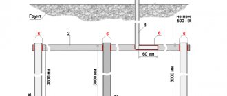
When the calculations are completed, we select the correct location to install the circuit. We select a geometric figure, in accordance with the shape of which the electrodes will be located. We draw a circuit diagram, taking into account the types of materials used. In the diagram we indicate the number of electrodes used, the connecting strip, their length, cross-section, diameter, installation depth.
The most optimal circuit organization scheme is considered to be a triangle. However, any other geometric shape will do. The figure below shows four variants of the figures.
All ground loop circuits are divided into 2 types.
Closed
Their advantage is reliability, since even if the jumper between the electrodes is damaged, another jumper remains (on the other side). The figure below shows a closed circuit in the form of a triangle.
Linear
In this circuit, all electrodes are on the same line. Connections are made sequentially. The disadvantage of this method is that if one of the jumpers fails, the entire further chain becomes inoperable (in accordance with the daisy chain principle). The linear organization diagram is shown in the figure below.
Connection diagrams
The most popular grounding connection schemes are:
Closed, in the shape of a triangle (Fig. 3). The main advantage is more stable and reliable operation. If the jumper between the rods is damaged, the circuit will still continue to work (but on the other side).
Linear (Fig. 4). Serial connection in one line of buried metal pegs. The disadvantage of such a circuit is that if the jumper fails, the circuit will not work.
In addition to the above types of contour diagrams, you can also use the following forms:
Required tools and materials:
- welding machine;
- cutting tool (grinder);
- shovel;
- perforator;
- spanners;
- resistance meter;
- current meter;
- voltage meter.
In addition to the above devices, you must use:
- The corner is made of corrosion-resistant steel, its dimensions can be 50x50, 60x60 mm. Length – more than 2 meters. It is also possible to use a steel pipe with a diameter of at least 32 mm with a wall thickness of more than 3.5-4 mm.
- Metal strips (3 pieces). Their parameters: length – 120-130 cm; width – 4-6 cm; wall thickness – 4-6 mm.
- Steel strip made of stainless material 40x4, 50x5 mm. It connects the ground loop and the porch of the house.
- Bolts M10, M8.
- The conductor is copper, with a diameter of at least 6-7 mm2.
All the above parameters must be checked using a meter.
Circuit installation
Installation work consists of several successive stages.
Preparation of materials and tools
To complete the work you will need the following tools:
- welding machine;
- Bulgarian;
- bayonet shovel;
- perforator;
- heavy sledgehammer;
- spanners.
Necessary materials:
- A metal corner (preferably stainless steel) measuring 50x50 millimeters and 2 meters long. If there is no corner, a pipe with a diameter of 32 millimeters and a wall thickness of 3.5 millimeters or fittings will be suitable.
- Metal strips 40x4 millimeters. Designed for installation from the system to the home.
- Bolts M8 or M10.
- Copper conductor with a thickness of 6 square millimeters.
Selecting a location
The first stage of the work is to decide where to make the ground loop. The security of the system depends on the correct choice. To create a contour, you need to choose a place where the presence of a person or pet is excluded.
It is best to place the system in a secluded place, for example, along the fence behind the house. It is recommended to fence off the danger zone with a fence, border, decorative boulders, etc.
Excavation
It is necessary to dig a trench in the form of a selected geometric figure. If we are talking about a triangle, create a figure with sides of 120 centimeters (the optimal distance proven by experience). The recommended trench depth is 50 - 70 centimeters. The same trench is dug towards the electrical panel.
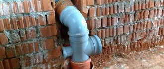
Assembly of the structure
The electrodes are driven into the ground to a depth of two meters. Only the tops should be visible, which are subsequently used to create welding joints.
Plates (strips) are welded to the tops of the installed electrodes. The result should be a metal frame in the shape of a triangle. Another plate is placed in the trench leading to the electrical panel. This plate is secured to the nearby vertex of the triangle by welding or a holder.
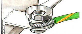
Next, attach the cable to the plate. For this purpose, a bolted connection is used. For subsequent connection of the grounding bus, it is better to use a copper conductor. A screw is attached to the grounding bus (by welding) and a connection is made to the core. The copper cable is connected to the screw using a pair of washers and nuts.
Note! The bolted connection must be visible on the surface and accessible for inspection activities.
At the circuit manufacturing stage, special attention should be paid to the strength of the connections. Welds are tapped with a hammer, and bolted connections are tightened with a wrench.
The last stage of installation work is filling the trench with soil.
Advice! To improve soil conductivity, it is advisable to pour a saline solution under the base of all electrodes. However, this action has a downside - the metal will rust faster.
Grounding device for a private house
Some older power lines have no protective ground at all. They all must change, but when this will happen is an open question. If this is your case, you need to make a separate circuit. There are two options - do the grounding in a private house or country house yourself, with your own hands, or entrust the implementation to a campaign. The company's services are expensive, but there is an important advantage: if problems arise during operation due to improper functioning of the grounding system, the company that carried out the installation will compensate for the damage (must be specified in the contract, read carefully). If you do it yourself, everything is on you.
Grounding device in a private house
The grounding system of a private house consists of:
- grounding pins,
- metal strips combining them into one system;
- lines from the ground loop to the electrical panel.
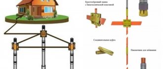
What to make grounding conductors from
A metal rod with a diameter of 16 mm or more can be used as pins. Moreover, you cannot take the reinforcement: its surface is hardened, which changes the distribution of current. Also, the hardened layer in the ground breaks down faster. The second option is a metal corner with 50 mm shelves. These materials are good because they can be driven into soft soil with a sledgehammer. To make it easier to do this, one end is sharpened, and a platform is welded to the other, which is easier to hit.
You can use pipes, a corner, a metal rod as rods
Sometimes metal pipes are used, one edge of which is flattened (welded) into a cone. Holes are drilled in their lower part (about half a meter from the edge). When the soil dries out, the distribution of the leakage current deteriorates significantly, and a saline solution can be poured into such rods, restoring the functioning of the grounding. The disadvantage of this method is that you have to dig/drill holes under each rod—it won’t be possible to hammer them in with a sledgehammer to the required depth.
Pin driving depth
The grounding pins should go into the ground below the freezing depth by at least 60-100 cm. In regions with dry summers, it is desirable that the pins be at least partially in moist soil. Therefore, corners or a rod 2-3 m long are mainly used. Such dimensions provide a sufficient area of contact with the ground, creating normal conditions for the dissipation of leakage currents.
What not to do
The job of protective grounding is to dissipate leakage currents over a large area. This happens due to the close contact of metal grounding conductors - pins and strips - with the ground. Therefore, grounding elements are never painted. This greatly reduces the current conductivity between the metal and the ground, making the protection ineffective. Corrosion in welding areas can be prevented with anti-corrosion compounds, but not with paint.
The second important point: grounding must have low resistance, and for this good contact is very important. It is provided by welding. All joints are welded, and the quality of the seam must be high, without cracks, cavities and other defects. Please note once again: grounding in a private house cannot be done using threaded connections. Over time, the metal oxidizes, breaks down, the resistance increases many times, the protection deteriorates or does not work at all.
Only welded joints can be used
It is very unwise to use pipelines or other metal structures located in the ground as a grounding conductor. For some time, such grounding works in a private house. But over time, the pipe joints become oxidized and destroyed due to electrochemical corrosion, activated by leakage currents, and the grounding becomes inoperative, as does the pipeline. Therefore, it is better not to use these types of grounding conductors.
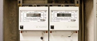
Checking the resistance in the circuit
Another job to be done is checking the loop resistance. The ideal option is to have a special testing device. The name of the device is F41023-M1.
However, the cost of such equipment is high - only professionals have devices. It makes more sense to invite employees of the energy company to check. Specialists will take measurements and, based on the results obtained, issue a technical passport and draw up a protocol for the grounding device.
At home (in the absence of a device and outside help), the resistance is checked in a simpler way: connect a 100-watt light bulb (or even more powerful) to the network. One contact of the lighting device is connected to the ground loop, the other to the phase. A bright light indicates that the system has been installed correctly. A dim glow indicates weak contact between sections of the structure. In other words, it is necessary to recheck the entire system and find connections that are not strong enough.
It is considered that the circuit is made correctly if a 2 kW electrical appliance connected between the phase and ground will work, and the voltage drop in the specified area will not exceed 10 Volts.
According to the rules of the PUE (1.7.101), the conductor resistance in any season of the year should not be higher than 2.4 and 8 Ohms at line voltages for 660, 380 and 220-volt three-phase current sources, respectively. The same applies to 380, 220 and 127 volt single phase power supplies.
Note! In a TT grounding system, a low resistance level is a good sign. However, if we are talking about a TN-CS system, the resistance level should not be less than 4 Ohms, i.e., the indicator of the transformer substation. Otherwise, the load on the grounding of the overhead line will be transferred to the circuit of a private house.
Types of ground loops
Grounding circuit: PUE standards
There are several main types of grounding systems:
Traditional grounding systems
Such a grounding system consists of one electrode located horizontally, and the other two - vertically. The first element is made from a metal strip, and the others are made from reinforcement fragments. All these elements must be checked and made sure that they are made according to the specified standard dimensions. In the case when grounding is installed in a residential building, it is necessary to install grounding in the part where residents of the house are less likely to visit. This may be the northern part of the building, where there is more shadow and the ground remains wetter.
The disadvantages of this installation option include:
- complexity and difficulty of construction;
- most parts of the ground loop are made of ferrous metal, which is very susceptible to corrosion;
- equipment located in the upper layers of the earth is affected by changes in humidity and temperature.
Deep grounding systems
This grounding system assumes the absence of many of the disadvantages of the previous type. Manufactured in a modular-pin manner.
Its advantages include:
- higher manufacturing accuracy of all parts;
- long service life;
- any weather is not a hindrance, since the grounding electrodes are installed at a great depth;
- no need for constant maintenance;
- fairly simple grounding calculation;
- ease of installation.
After completing installation work, it is necessary to check the operation of all equipment. Follow the calculations of the ground electrode, thereby ensuring the quality of all connections. Ground resistance measurements are carried out by employees of specialized and licensed laboratories.
External grounding systems
This grounding system has a circuit of the type that is used in transformer substations. It includes:
- vertical electrodes;
- horizontal grounding device.
The ground electrode is made of 4 strips of 40-50 mm each. The external ground loop must be located at a distance of more than one meter from the wall. The structural element, located horizontally, is placed in a trench to a depth of 50-70 cm from the ground surface.
Most common mistakes
When creating a contour, a number of mistakes should be avoided:
- If you decide to turn to electricians, you need to pay special attention to the quality of the materials that the workers are going to use. Some contractors seek to reduce the cost of their services by saving on electrodes by installing conductors with low conductivity (for example, rusted fittings). Low-quality materials significantly reduce the effectiveness of protection or even make the idea completely pointless.
- The grounding device is too far from the house.
- Install the circuit in a dry place. Water improves conductivity - for the system to work effectively, it must be in a humid place. If there is no such place, you will have to think about artificial humidification.
- Combining the grounding loop with lightning protection. If the switchboard does not have a surge protection device installed that opens the circuit in response to an overcharge, a significant current from the lightning rod will damage the electrical equipment.
The grounding loop is the most important measure to ensure the safety of using electrical appliances in a private home. If you decide to do all the work yourself, you must carefully adhere to all technical rules and recommendations, including safety precautions. If self-confidence is not enough, it is better to seek help from specialists.
Selection of scheme, calculation and installation of a ground loop in a private house
According to the electrical standards of past decades, the ground loop in private homes was not a mandatory element of protection. The loads on the electrical networks were relatively small, and steel pipes coped well with current leakages.
However, over time, plastic and composite products began to be used instead of metal communications. In addition, a large number of electrical household appliances have appeared in country houses: air conditioners, heating equipment, powerful computer and refrigeration equipment.
As a result, grounding loops have become almost a prerequisite for organizing a powerful and safe electrical system in private homes. If you wish and have basic knowledge of electrical engineering, you can create a grounding loop with your own hands.