Documentation
Any measuring device has a relative error. Usually this parameter is fixed and individual for each multimeter. It is reflected in the documentation attached to the product. Error data is indicated by a percentage or plus-minus sign. The manufacturer indicates the maximum permissible deviation range, which is obtained after calibration at the factory.
However, before use, you can determine the accuracy of the multimeter yourself. Often two different copies produced by the same manufacturer may have different errors.
For a correct assessment, it is better to use the absolute figure, which is given at the end of the error scale. For example, if you need to make measurements where the voltage range is 2 V, the error should not be more than ±41 mV.
If the multimeter's passport data calculates the error as a percentage, for example, ± 0.5% and ± 1D, then we calculate. 0.5% of 2 V The resulting value is 40 mV, in this case the unit of lesser digit is 1 mV.
If you find that in a given measurement segment the multimeter shows deviations greater than those expected, it requires calibration. If the procedures are carried out correctly, the readings will be more accurate than those indicated by the manufacturer in the product passport.
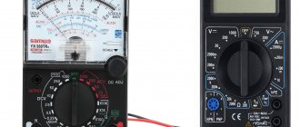
Digital multimeters
The simplest digital multimeters are portable. They are 2.5 digital digits wide (accuracy is usually about 10%). The most common devices are with a bit resolution of 3.5 (the accuracy is usually about 1.0%). Slightly more expensive instruments with a bit resolution of 4.5 (accuracy is usually about 0.1%) and significantly more expensive instruments with a bit resolution of 5 bits and higher are also produced (for example, the 3458A precision multimeter manufactured by Keysight Technologies (until November 3, 2014, Agilent Technologies) has 8.5 digits). Among such multimeters there are both portable devices powered by galvanic cells and stationary devices powered by alternating current. The accuracy of multimeters with a resolution of more than 5 strongly depends on the measurement range and the type of measured value, therefore it is discussed separately for each subrange. In general, the accuracy of such devices can exceed 0.01% (even for portable models).
Many digital voltmeters (for example V7-22A, V7-40, V7-78/1, etc.) are essentially also multimeters, since they are capable of measuring, in addition to DC and AC voltage, also resistance, DC and AC current, and Some models also provide measurement of capacitance, frequency, period, etc.). Also classified as a type of multimeter are scopmeters (oscilloscopes-multimeters), which combine a digital (usually two-channel) oscilloscope and a fairly accurate multimeter in one housing. Typical representatives of scopmeters are AKIP-4113, AKIP-4125, hand-held oscilloscopes of the U1600 series from Keysight Technologies, etc.).
The digit capacity of a digital measuring device, for example, “3.5” means that the device display shows 3 full digits, with a range from 0 to 9, and 1 digit with a limited range. Thus, a device of the “3.5 digit” type can, for example, give readings in the range from 0.000 to 1.999; when the measured value goes beyond these limits, switching to another range (manual or automatic) is required.
Indicators of digital multimeters (as well as voltmeters and scopmeters) are made on the basis of liquid crystals (both monochrome and color) - APPA-62, B7-78/2, AKIP-4113, U1600, etc., LED indicators - B7- 40, gas-discharge indicators - B7-22A, electroluminescent displays (ELD) - 3458A, as well as vacuum fluorescent indicators (VFD) (including color ones) - B7-78/1.
The typical error of digital multimeters when measuring resistance, DC voltage and current is less than ±(0.2% +1 least significant unit). When measuring alternating voltage and current in the frequency range 20 Hz...5 kHz, the measurement error is ±(0.3%+1 least significant unit). In the high frequency range up to 20 kHz, when measuring in the range from 0.1 of the measurement limit and above, the error increases significantly, up to 2.5% of the measured value, at a frequency of 50 kHz it is already 10%. As the frequency increases, the measurement error increases.
The input resistance of a digital voltmeter is about 10 MΩ (does not depend on the measurement limit, unlike analogue ones), the capacitance is 100 pF, the voltage drop when measuring current is no more than 0.2 V. Portable multimeters are usually powered by a 9V battery. The current consumption does not exceed 2 mA when measuring constant voltages and currents, and 7 mA when measuring resistance and alternating voltages and currents. The multimeter is usually operational when the battery is discharged to a voltage of 7.5 V.
The number of digits does not determine the accuracy of the device. The accuracy of measurements depends on the accuracy of the ADC, on the accuracy, thermal and temporal stability of the radioelements used, on the quality of protection from external interference, on the quality of the calibration performed.
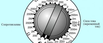
Typical measurement ranges, for example for the popular M832 multimeter:
- constant voltage: 0..200 mV, 2 V, 20 V, 200 V, 1000 V
- alternating voltage: 0..200 V, 750 V
- DC current: 0..2 mA, 20 mA, 200 mA, 10 A (usually via separate input)
- AC: no
- resistance: 0..200 Ohm, 2 kOhm, 20 kOhm, 200 kOhm, 2 MOhm.
Options for determining error
How to calibrate a device is a rather complicated question, because there is no single methodology that describes these actions. Each user selects a method that is convenient for him, which best matches the model of his multimeter and is affordable.
Most multimeters are used to measure voltage, test electrical networks, measure resistance, they test transistors, capacitors, and some models are capable of measuring temperature. It doesn't matter what model you have. The calibration method may be the same for several products from different companies.
Basically, multimeters have a standard circuit. They convert the resulting readings into voltage, which is compared with a reference value called VREF. Thanks to this, it is possible to obtain measured values.
In order for them to be as accurate as possible, it is necessary that the reference voltage be close to the ideal. Since its value in most cases is set by a conventional resistive divider, the accuracy of the data may depend on how fresh the device’s battery is. If it is discharged, the multimeter will produce incorrect data.
The inaccuracy of the reference voltage will make all other values obtained using a multimeter incorrect. The calibration technique requires precise setting of this particular initial parameter.
Advice. Before setting up the device, replace the battery or make sure it is well charged.
Many multimeters have adjustment elements for calibration. These are variable resistors with additional leads. It’s easy to find them; they have special markings on the board.
If the device is an old model and the board does not have such markings, find their approximate location, and then compare with the multimeter circuit.
Operating principle
The work of any tester is based on the principles of measuring quantities. In addition, it is built in accordance with Ohm's law.
You may be interested in Installing an ammeter
There are a number of principles for using the tester for different types of measurements:
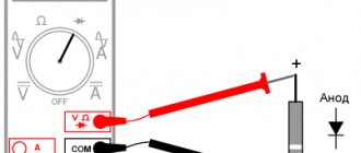
- Direct measurements. They are produced by directly connecting the probes to the object. The result will be displayed on the device.
- Indirect measurements. Occur by performing several sequential actions. In this case, the required indicator is the calculated value.
- Non-electric quantities. Additional indicators, calculated using special sensors installed in the device.
The analog tester has a measuring head that connects to 2 points of the electrical circuit. This is how voltage is measured. To measure current, a measuring voltage is connected in parallel to the circuit.
Work with gloves
To measure resistance, current is applied to it.
The work of the digital tester is based on the ADC. It compares the input signal with the reference signal. Voltage measurement occurs directly. The current is measured according to the voltage drop across the internal resistors. Resistance measurement - based on the resistor's performance relative to a fixed current.
The principles also determine the characteristics of the device:
- simple models have a bit depth of 2.5 and an error of 10%;
- average - 3.5 and 1%, respectively;
- good - 4.5 and 0.1%;
- professional - over 5 and no more than 0.01%, respectively.
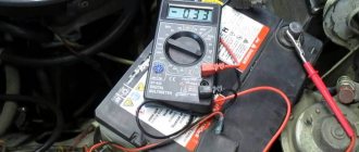
Electrical parameters are also measured in cars
Calibrator or reference voltage
For calibration, a special device such as AKIP-2201 can be used. It provides readings with high accuracy, and you can use them as a guide to adjust your multimeter.
However, the cost of such a calibrator is high, so it is used only by specialized companies that deal with instrument calibration and metrology issues.
A more affordable option for calibration at home is to use a reference voltage source. It can be used to calibrate popular multimeters from Mastech and other brands.
As a source, you can use the REF5050 5 V chip or a special AD584 control source, or any other high-precision source that you can find. It has a claimed accuracy of 0.05%. By connecting the multimeter to the circuit, the trimmers achieve the correct readings of the device.
It was a pity to throw away the old man. I opened the multimeter again and made a map of the resistances of the trimming resistors, so that if necessary, I could return everything back. Unfortunately, it was not possible to find a circuit diagram for this particular multimeter. Only a circuit was found for a multimeter with a similar name - MS8222G, but it only partially coincided with the MS8222H circuit.
A muddy video [1] helped, where the author explained in broken English which resistor is needed for what, and how to calibrate the multimeter.
View of trimming resistors:
Purpose of trimming resistors:
VR1 : VREF+ trim (100 mV, measured between pins 40 and 44 of IC2). This setting is basic and affects all modes.
VR2 : ADC setting. In the video [1], the author claims that this setting sets the sensitivity of the voltmeter, but in my case, the position of the VR2 slider for some reason did not affect anything.
VR3 : Temperature meter lower limit calibration.
VR4 , VR5 , VR6 : Inductance meter setting.
VR7 : Temperature meter upper limit calibration.
VR8 : frequency meter calibration.
VR9 : Capacitance meter calibration.
The essence of the setting is as follows - with resistor VR1 you must first calibrate the level of the reference voltage VREF+ 100 mV, which should appear on the 44th leg of the IC2 7106-44 microcircuit. This level must be measured relative to pin 40 of the same microcircuit, and in order to get to the pins of the microcircuit, you need to remove the LCD indicator.
Next, resistor VR2, judging by the video, adjusts the voltmeter readings, and resistor VR8 adjusts the frequency measurement. In my case, it was enough for me to tighten VR1 so that the voltmeter began to accurately display voltages. No matter how I twisted VR2, it did not affect the accuracy in any way, so I returned it to its previous position. I checked the resistor measurements - normal. I didn’t try other modes because I didn’t have a calibration device.
For disassembly, you need to unscrew two screws near the battery compartment and remove the bottom of the multimeter. You will see the board and 4 screws that secure the mode switch to the board. Attention: these screws do not need to be unscrewed! All that is needed to get to the trimmers is to separate the multimeter board from its front panel. The board is held on the front panel only by the switch handle. To remove the front panel, carefully lift the board from the input jacks with a little force. The mode switch slider will move off its axis and remain on the front panel, and the board will be removed.
[Links]
1 . Mastech MS8222H calibration site:youtube.com. 2 . Guide: How to use a multimeter.
Stages of the procedure
First of all, you need to do the following:
- adjust the divider, which determines the initial VREF, for this you will need potentiometer VR1;
- switch the multimeter to the 200mV division to measure direct current;
- Use a voltmeter whose accuracy is known and apply the required voltage to the input. The closer it is to the specified range point, the better: for example, a voltage of 190 mV is suitable;
- After this, you can adjust the multimeter readings. If you change the polarity, the device should react and display the corresponding sign.
In addition, the operation of the device is checked in other ranges. If it is working properly, no discrepancies will appear. In order to monitor the indicators, you can re-measure the voltage using pin 36 of the ADC.
In this case, the voltage should be 100 mV. However, you should not expect high accuracy of the device. The fact is that manufacturers often install single-turn potentiometers with a resistance of 20 kOhm, as a result of which it is not possible to obtain highly accurate readings from the device.
Variable resistor VR2 is used to calibrate the multimeter when working with alternating voltage. You will need to set the multimeter to the same range that was used previously - 200 mV, but the voltage should already be given as variable.
190 mV is supplied to the output, the frequency should be 100 Hz. Evaluate the data obtained and adjust the multimeter readings, trying to get them as accurate as possible.
The capacitance meter is adjusted using variable resistor VR3, but this requires a reference capacitor. Thanks to it, it is possible to measure the force coefficient. The output voltage of the multimeter in this case will be directly proportional to the value of the capacitance being measured; measurement is required using an ADC.
How to check a multimeter for accuracy
A mandatory condition for using the device is to check its functionality. The most common option is to connect the device to a power outlet in parallel. Then the indicators are checked using instruments or batteries.
The battery can help a lot. The point is that, as a result of changing the polarity of the probes, the voltage measurements give the same result.
The verification mechanism in this case is simple:
- select the mode corresponding to the DC voltage measurement;
- Measuring limits are set at 20 V.
There is 1.5 volts in the AA element.
A correctly functioning battery gives a measurement result of 1.35V. In some cases, up to 1.2V is allowed.
Then the test is repeated:
- multimeter probes are connected to the battery contacts;
- the load element is connected in parallel;
- there is a pause (about 35 seconds);
- the obtained result is checked.
For your information . If the remaining battery level is 1.1 V, it can only be used in a household appliance that consumes a small amount of energy. However, the quality of work will decrease significantly.
Maximum accuracy is achieved if the device is set to the lowest voltage limit. This makes it easy to determine the measurement error of the device.
The car battery has 12 volts
A device reading of up to 1.6V does not indicate that the device is inaccurate. Often, battery manufacturers do this specifically to ensure longer battery life.
A good way to determine the accuracy of the device is to close the contacts of the device in resistance measurement mode.
You might be interested in Zener diode testing rules
If you try to close the contacts of the device in a different mode, it may fail.
After making a contact closure, the indicator should show “0”. Any other value is evidence of malfunction and inaccuracy of the device.