Bipolar power inverting amplifier circuit
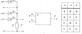
The basic circuit of a bipolar power inverting amplifier looks like this:
Here we see two resistors and the op-amp itself. We apply a signal to the input, and then remove the amplified signal from the output. As you can see, the non-inverting input of the op-amp is grounded. How does the scheme work? Here we see feedback. That is, the signal from the output is fed back to the input through resistor R2. Our amplifier is inverting, since the output signal is 180 degrees phase shifted relative to the input signal. This means that at the node where two resistors and the inverting input are connected, the output signal will arrive with a minus sign. Such feedback is called negative feedback ( NFC ) . It reduces the high gain of the op amp to the values we need.
In a NON-inverting amplifier, feedback is via voltage, and in an inverting amplifier, feedback is via current.
If you read the article about the op-amp, then you probably remember that if one of the inputs of the op-amp is connected to ground, then the other input has exactly the same potential. In this case, our non-inverting input is connected to ground, therefore, the inverting input will have exactly the same potential, that is, 0 Volts. Such an input is also called imaginary (virtual) earth . As Wikipedia says, “imaginary is false, counterfeit, false.”
The voltage gain of any amplifier is expressed by the formula
So what do we get in the end?
Input voltage from the formula above
But since our amplifier inverts the input signal, therefore, at the output we will have a voltage with a minus sign, that is, -Uout.
In this case, the current I2 will be expressed by the formula:
From here we find the gain
Since the input resistance of the inverting input is infinitely large, therefore, current will flow only through the circuit R1->R2. There cannot be two different currents in one branch, so it turns out that
As a result, our formula is reduced and we get
What is an operational amplifier?
Operational amplifiers are microcircuits that can look different.
For example, this picture shows two Russian-made operational amplifiers. On the left is the K544UD2AR operational amplifier in a plastic DIP case, and on the right is an op-amp in a metal case.
At first, before I got acquainted with op-amps, I constantly confused microcircuits in such metal cases with transistors. I thought that these were such clever multi-emitter transistors