Features of automotive wiring
Indeed, all these wiring harnesses that encircle the car from top to bottom perform the only task - to ensure the uninterrupted transmission of electrical impulses between the components of a particular system. And if one of the wires has poor contact, or even worse, the terminal is burnt out or oxidized, then the operation of the circuit will be disrupted or even fail.
Replacement is simple; it’s more difficult to find the location of a break or short circuit with your own hands, especially if you don’t know how to do it.
In this article we will try to answer many questions, including:
- how to test the wiring in a car to find a fault;
- how to properly repair the actuator;
- how to restore bad contact;
- how to solve other electrical problems.
Troubleshooting wiring requires basic knowledge and precise tools.
What's under the hood
In the engine compartment there are many wires that perform a wide variety of functions:
- transmitting high voltage pulses from a current source (generator or battery) to the engine cylinders;
- transmitting data from various sensors;
- ensuring continuous operation of the fuel supply system, lighting fixtures, etc.
The wiring of the ignition system deserves the greatest control.
What's in the cabin
Inside the car, intended for the driver and his passengers, there are even more wires, since there are:
- Automotive system controls:
- control of external lighting devices (road lighting, maneuvering signals and rear brake lights);
- management of audio devices;
- automatic transmission control;
- control of electronic assistants (cruise control, automatic windshield wipers, navigation system);
- Control devices and sensors;
- Active safety systems:
- electric seat belts;
- driver and front passenger airbag mechanisms;
- Comfort features:
- air conditioner;
- window regulators;
- musical equipment;
- heating systems for windows, mirrors, seats, etc.
Replacing the wiring in a car will necessarily require disassembling the instrument panel.
Note! Wiring harnesses run through the interior to the rear of the car. Therefore, there is a maximum concentration of electrical wiring inside the machine.
How to detect a fault
If one of the electrical devices or actuators stops working, then there is no need to rush to replace it. It cannot be ruled out that the cause of the failure is hidden in a wiring malfunction, and installing new equipment will not solve the problem.
Working with a multimeter makes it easy to determine faulty wires
Any factory manual for a car recommends starting the search for the cause of malfunctions by ringing the electrical wires connecting this device or mechanism to other components.
To do this you need to arm yourself with:
- multimeter;
- or a 12 Volt signal lamp with connecting wires.
How to use a multimeter
In the video in this article you can see some aspects of working with measuring equipment when carrying out work to detect breakdowns in the on-board electrical network. And the main tool of any auto electrician has been and remains a multifunctional digital device - a multimeter. (See also the article VAZ 2105 wiring diagram: description.)
The price of this device is low, which makes it affordable to most car enthusiasts.
For reference: A multimeter is a universal device that simultaneously combines an ohmmeter, an ammeter and a voltmeter. A voltmeter is responsible for measuring the voltage of the on-board circuit, an ammeter measures the current, and an ohmmeter determines the resistance accordingly.
Voltage check
So, if one of the electronic components in a car stops working, then the first thing you need to do is check the voltage of the electrical circuit that connects it to other devices. (See also the article Gazelle wiring diagram: how to install.)
For this:
- Switch the multimeter to voltmeter mode;
- We connect one of the probes of the device to the negative terminal of the battery (if the device being tested is under the hood) or to the ground of the car, trying to choose a place on the body with good contact;
- We connect the second probe to the supply wire in the circuit being tested, having previously removed it from the terminal of the device or instrument.
If values appear on the display, there is voltage in the wire and the wire itself is working. We carry out the operation with other wires, and when we find a point where there is no voltage in the network, we determine that the source of the fault is located in this segment.
The photo shows the process of working in the engine compartment
Note! In some car electrical circuits, voltage is only present if the ignition key is set to a certain position.
Finding a short circuit
This procedure is characterized by the complete absence of voltage in the circuit.
For this:
- the fuse responsible for the circuit being tested is removed;
- the multimeter is switched to voltmeter mode;
- one of the probes is connected to the fuse connection terminals at a time when all other devices and equipment in this circuit are de-energized;
- move the wire - if values appear on the screen, then the wire is shorted.
It is better not to let the wires in the car reach this state.
Note! Most often this happens with wiring in places where the insulation has worn through. A similar test for finding a short circuit can be carried out with any other element of the circuit, incl. with switches.
Checking the quality of grounding
Since the vast majority of cars have a single-wire wiring diagram, and all electrical equipment receives “-” through the metal body of the car, the quality of grounding of devices and mechanisms plays a decisive role.
But during operation, body parts:
- rust;
- oxidize;
- get loose;
and electrical equipment connected to the housing loses electrical contact, they begin to work intermittently. To ensure their serviceability, you should check the reliability of grounding.
Such contacts are the first to come under suspicion.
The algorithm for checking the reliability of connecting electrical equipment and other elements to the vehicle ground will be as follows:
- Disconnect the battery and connect one of the multimeter wires to the ground of the car;
- We connect the second wire to the grounding point or to the connection that we are checking;
- If values appear on the screen, check them with the factory parameters, and if they are close, then the grounding is in order.
Circuit continuity check
This procedure is necessary in order for the car owner to determine whether everything is in order with the wiring and whether there is a break in the circuit. (See also the article Niva Chevrolet wiring diagram.)
The procedure is as follows:
- Disconnect voltage from the circuit by removing the fuse or disconnecting the terminal on the battery;
- Check the electrical circuit for continuity by attaching multimeter probes to its ends;
- Then connect one of the probes to the vehicle ground;
- If values appear on the screen, there are no breaks in the circuit;
- If the screen remains static, there is a break somewhere in the electrical circuit.
Electrical equipment will not work with such a contact.
Subscribe to the newsletter
A modern car will not work without electricity: it is necessary to start the engine, illuminate the road and interior, and operate electronic systems.
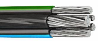
Navigation, air conditioning, audio systems, alarms and much more - all this is unthinkable without electricity. Accordingly, the number of wires in a car is calculated not even in tens, but in hundreds of meters. The specific operating conditions of the wiring place special demands on it. In winter, a car often sits in the cold for a long time, and during operation the temperature in the cabin and under the hood quickly rises. Wires for automotive wiring are often subject to mechanical stress, oil and fuel. At the same time, they are subject to special requirements regarding the duration of operation, since any motorist does not want to spend time and money on replacing wires every month. That is why all manufacturers use wires of the PGVA, PVA, PVAM brands, which correspond to specific operating conditions.
Main advantages of car wires
Wires for automotive wiring have the following main advantages:
- recommended application temperature from -40ºС to +105ºС;
- high resistance to insulation cracking;
- resistance to gasoline, diesel fuel, engine oil, acidic environments;
- do not spread flame;
- resistant to repeated impacts at high acceleration;
- high flexibility, elasticity and wear resistance of insulation;
- high resource and long service life.
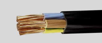
Such advantages can be achieved by using a copper stranded conductor of round cross-section, a special insulation material, as a current-carrying cable. A large number of cores not only ensures reliability, but also acts as protection during overloads. The wire insulation material is PVC plastic, it is characterized by high performance characteristics and resistance to aging. Rubber is used as insulation for power wires - a classic material that does not need additional recommendations.
Selection of automotive wires
When choosing wires for automotive wiring, fire safety requirements come to the fore. It is for this reason that it is necessary to abandon rigid wires with insulation that is prone to cracking during operation. Cables in a car often have to be laid through bulkheads, along corners, where they are subject to friction that occurs during vibration of the body and large components. The temperature under the hood in the sun reaches significant values, and in winter cold the engine cools down very quickly at night. All these destructive factors should not affect the insulation of the wire used.
The core of the automobile cable must conduct electric current well at rated power; its loss and overheating of the wire during fuse burning are unacceptable. In the latter case, the temperature of the copper core should not exceed that at which the insulation begins to melt. That is why it is recommended to use special wires for automotive wiring, produced by both domestic and foreign industries.
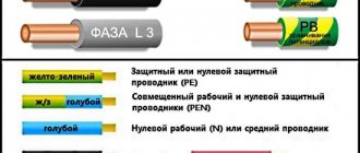
The color of the wires is of great importance, as it makes it easy to navigate the complex power supply system of the car. There is no standard classification by color scheme, but modern databases, which every car enthusiast can access today, contain all the necessary information on domestic and foreign cars.
I decided to put this article together because of the questions: What cables and wires are used in the automotive industry? I’ll write right away that beautiful white wires like PUGNP are not suitable, and not only in a car, but even in the power supply of your home, forget about them and live in peace. Flexible network cable PUGNP, analogue of ShVVP
For the home, black VVG ng LS, or without LS, there are others, but this one is the most affordable and of high quality.
A single-core flexible “black” wire in a “rubber sheath”, designed for connecting welding machines, machine tools, mobile devices such as concrete mixers, circular machines, etc. And also for “connecting masses in a car” (we take into account places where there is oil and temperature), and for making wires for “lighting a cigarette”.
Optional equipment
During operation, car owners often install additional electrical equipment:
- Alarm;
- More powerful lighting fixtures;
- Audio and video equipment, etc.
Integrating them adds wiring to the vehicle and also puts stress on the electrical system. Moreover, a number of “new” electricity consumers cannot be switched off, for example, alarm systems, which means that the likelihood of rapid battery discharge becomes very important.
Current leakage is also determined using a multimeter
If your car begins to have difficulty starting after a long period of parking, then you should determine the cause of the current leak. A multifunctional device switched to ammeter mode will also help you find a leak.
Tip: Don’t forget to set the measurement range to 10 Amps, since the current in the car’s on-board network is constant.
Selecting a cable and wire for installing wiring in a car.
If for some reason a fire occurs, the insulation of the wires should not spread fire.
The domestic cable industry produces a wide range of wires and cables suitable for power wiring in vehicles.
| Cable | Purpose | Section, mm2 | Insulation | Operating temperature |
| NV, NVM | mounting | 0,5…2,5 | PVC plastic compound | — 50°С…+ 105°С |
| PVA | autotractor | 0,5…95 | PVC plastic compound | — 40°С…+ 105°С |
| PGVA | autotractor | 0,5…95 | PVC plastic compound | — 60°С…+ 70°С |
| PVAM | transport | 0,5…6,0 | PVC plastic compound | — 40°С…+ 105°С |
| PVEp-M | power | 2,5…70 | Rubber | — 60°С…+ 100°С |
| PVKV | output | 0,75.120 | Rubber | — 60°С.+ 180°С |
| PV3 | installation | 0,5.95 | PVC plastic compound | — 50°С.+ 70°С |
Foreign industry produces special wires and cables for power wiring in cars. These cables are ideally suited to their requirements.
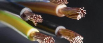
They are distinguished by a translucent shell (insulation) of red or brown color and a characteristic weave of a multi-wire conductor, which consists of bundles of wires twisted together. Inexpensive cables have wires made of plain copper, while more expensive ones have wires made of oxygen-free copper, which gives the wires lower resistance and therefore lower losses.
Cables have standard markings, for example: Power Cable - power cable
Belsis, Proleader , etc. — trademark of the supplier or manufacturer
OFC (Oxygen-Free Copper ) - wire made of oxygen-free copper
No. 20 - No20 - Nr20 - #20 - gauge (size) of the conductive core of the 20 gauge cable, etc.
AWG - American Wire Gauge - American wire gauge
SWG - Standard Wire Gauge - Standard Wire Gauge BWG - Birmingham Wire Gauge - Birmingham Wire Gauge
Wires of the same caliber in different assortments differ slightly in the diameter of the wire (core). The AWG gauge is considered the main gauge for automotive power wiring.
| Gauge AWG | Diameter, mm | Section, mm2 | Resistance, Ohm/m | Analog, mm2 |
| 20 | 0,81 | 0,52 | 0,035 | 0,5 |
| 19 | 0,91 | 0,65 | 0,025 | 0,75 |
| 18 | 1,02 | 0,82 | 0,023 | 0,75 |
| 17 | 1,15 | 1,04 | 0,018 | 1,00 |
| 16 | 1,29 | 1,31 | 0,015 | 1,5 |
| 15 | 1,45 | 1,65 | 0,012 | 1,5 |
| 14 | 1,63 | 2,08 | 0,0088 | 2,0 |
| 13 | 1,83 | 2,62 | 0,0074 | 2,5 |
| 12 | 2,05 | 3,31 | 0,0054 | 3,0 |
| 11 | 2,31 | 4,17 | 0,0046 | 4,0 |
| 10 | 2,59 | 5,26 | 0,0036 | 5,0 |
| 9 | 2,91 | 6,63 | 0,0031 | 6,0 |
| 8 | 3,26 | 8,37 | 0,0024 | 8,0 |
| 7 | 3,67 | 10,55 | 0,0018 | 10,0 |
| 6 | 4,12 | 13,3 | 0,0014 | 16,0 |
| 5 | 4,62 | 16,8 | 0,0012 | 16,0 |
| 4 | 5,19 | 21,15 | 0,00091 | 25,0 |
| 3 | 5,83 | 26,68 | 0,00073 | 25,0 |
| 2 | 6,54 | 33,6 | 0,00057 | 35,0 |
| 1 | 7,35 | 42,4 | 0,00047 | 35,0 |
| 1/0 | 8,25 | 53,5 | 0,00037 | 50,0 |
| 00 | 9,27 | 67,5 | 0,00029 | 70,0 |
| 000 | 10,41 | 85,0 | 0,00023 | 95,0 |
| 0000 | 11,68 | 107,2 | 0,00018 | 95,0 |
To select the caliber (section) of the required cable, you need to know:
• maximum current consumed by the load;
• length of wires from load to battery;
• the rated voltage of the battery or other source that is intended to power the load.
The wire must have such a cross-section (thickness) of the wire conductor that the voltage drop across the wire resistance at maximum (long-term) current consumption is no more than 10% of the rated battery voltage. For pulsed (short-term) current consumption, a voltage drop of 15% is allowed. If the battery has a voltage of +12V, then the maximum permissible voltage drop should not exceed +1.2V (in a pulse up to +1.8V). The on-board voltage is +12V for gasoline cars and trucks, buses and light diesel cars. Diesel SUVs, heavy trucks and buses have +24V voltage.
The voltage drop across the conductor resistance causes power to be released and the conductor to heat up. Since the cable conductor (wire) is placed in an insulating sheath, the insulation prevents its cooling. To reduce heating, it is necessary to select the conductor cross-section taking into account the current density coefficient, which can have a value from 1 to 10 A/mm2 for different wire laying conditions. The average value of current density for an insulated wire laid in open wiring under normal temperature conditions corresponds to 6 A/mm2.
You can determine the maximum current consumed by the load by the rating of the fuse link of the load fuse or by the sum of the ratings of the inserts, if there are several loads. You can also determine the maximum current if the ULF output power is known, using the formula: Imax = P:6
Example 1 : calculate the cable gauge (section) if the load on the +12V battery is an audio power amplifier with an output power of 2x200W. The distance between the amplifier and battery is 6 meters.
Calculation:
Load power 2x200W = 400W
Maximum current 400W: 6 = 67A
Cable cross-section 67A: 6A/mm2 = 11.2 mm2
The cable is close to 11.2mm2 and is a #7 AWG 10mm cable.
This cable gauge has a conductor resistance of 6 meters (see table): 6 m x 0.0018 Ohm = 0.001 Ohm
Voltage drop across the cable conductor: 67A x 0.0011 Ohm = 0.74 V, which is 7.4% of the voltage + 12V
From the calculation it follows that the cable of caliber No. 7 is chosen correctly.
The cross-section of the current-carrying core is determined by the formula: S = πD2/4, where π = 3.14, D is the diameter of the core.
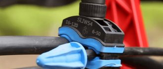
In order to prevent a fire from a short circuit of the power wire to ground, it is necessary to install a fuse holder (fuse link) on the “positive” wire. It is recommended to install a bulb-type fuse holder. It has a distinctive transparent sealed housing and can clamp wire up to #000 gauge. It is installed in the cable break in close proximity to the “positive” terminal of the battery. The fuse holder housing must be securely fastened. The fuse rating is selected to be 20...30% greater than the maximum current consumed by the load. The power wire from the fuse to the load should be one measured segment (from one piece). The presence of connections impairs reliability and can cause voltage losses at high power consumption. If for some reason you have to connect (splice) wires, then to connect the wires you need to use special “car” couplings or distributors (distributors) with reliable clamping contacts and an insulated housing made of heat-resistant plastic. In the absence of special connecting products, you can use terminal blocks, blocks and mounting boxes for industrial or household electrical wiring.
It is prohibited to use PVC insulating tape as an insulator for spliced cable ends.
If you need to install a tip on a wire for a contact bolted connection, then put a tip with an internal diameter of the shank corresponding to the caliber of the wire onto the wire stripped of insulation, crimp the shank with a special tool and it is advisable to solder the crimping point with solder. When laying the cable, it is recommended to place it in a corrugated tube of suitable diameter to avoid damage. If the wiring passes through places with sharp metal edges, the cable must be passed through rubber or nylon seals (wipers).
The connection between the load and the battery must be made with two oppositely polarized cables with insulation of different colors and the same caliber of the conductor.
It is prohibited to use a metal car body or chassis as a “negative” power cable, because Due to welds and poor contact connections, the load supply voltage may drop.
When assembling a car body, chassis and body parts are connected to each other using welding, riveting and threaded connections. These connections should ensure rigidity of the mechanical structure and galvanic contact between its individual parts, but for power currents they create body total transition resistance.
Mechanical connections during vehicle operation are subject to corrosion, rusting and oxidation, which leads to an increase in total transition resistances, which can reach 0.5...1.5 Ohms.
For example , if the load has a current consumption of 10A, then, according to Ohm’s law, a voltage loss of +10V will occur at a body transition resistance of 1.0 Ohm. If the load is powered by a +12V battery, then the remaining voltage of +2V will not be enough to power it.
Dictionary:
Electric current is the ordered movement of electric current in a conductor.
Current density is the distribution of electric current over the cross-section of a conductor.
Electric wire is an uninsulated or insulated conductor of electric current, consisting of one or more wires.
An electrical cable is one or more insulated conductors (current-carrying cores) enclosed in a protective sheath.
Power cable is an electrical cable for transmitting electricity.
Vladimir Sarychev shared his experience