What is a time relay (hereinafter referred to as R.V.) with a delay
A conventional relay is designed to turn on devices after receiving a signal. The time relay does not operate immediately, but after a period of time specified during its manufacture or configuration has passed. If executed with a delay, then another period is counted before turning on or off. It is also either provided during the manufacture of the device or configured (programmed).
TEST:
4 questions to test your theory
- Is it possible to use a delay relay like a regular relay?
a) You can’t, these are completely different devices.
b) Yes, for this we set the delay to zero. (loyal)
- Are relays with on-delay and off-delay different?
a) Yes, the first ones work out the delay before starting the main timer, the second ones only wait the time after the shutdown command. (loyal)
b) No.
- Is it possible to replace a relay with a turn-off delay with a relay with a turn-on delay?
a) No, these are different devices. (loyal)
b) Yes.
- Can a relay with a switch-on delay be replaced with two regular time relays?
a) Yes, if you connect them correctly. (loyal).
b) No.
Important to know - a relay with a delay in turning on and off 2 different devices
A conventional time relay turns on the device mounted after them for a period of time set during setup. That's not how latency devices work.
With switch-off delay - 1 relay operating in reverse
- The relay sends a signal to turn off the device.
- The delay time begins counting down, after the period has expired the device turns off.
If such a relay is mounted in front of a regular lamp, then it will not go out immediately after the switch is triggered, but after the delay time has passed.
With delayed start - 2 devices in one
- A signal is sent to the relay, it turns on its mechanism or electronic circuit.
- The delay time starts immediately.
- After the time has been counted, the relay turns on the connected device for the specified time.
In fact, these are two time relays connected in series.
Simple time relay for 220 V
This time delay relay is 220 Volt
is not galvanically isolated and is the simplest.
A thyristor
is used as a switching element .
As we said, a thyristor allows you to switch a load that is insensitive to the shape of the supply voltage: an incandescent lamp, a shadow lamp, a halogen lamp, and the like.
You cannot connect an LED driver or an energy-saving CFL type, or any electronic device that has a transformer at the input.
The minimum details of the circuit and the simplicity of the circuit will allow anyone to assemble this circuit, spending no more than 50–100 rubles.
However, please note that the circuit is not galvanically isolated and requires extreme caution and compliance with safety regulations!
The circuit works as simply as it looks. If you close contact S1, then gradual charging of C1 will begin. During the charging of this capacitor, thyristor VS1 will be open.
Load HL1 will have mains voltage. As soon as the capacitor is charged, thyristor VS1 will close and current will stop passing through it. Our device will shut down and the load will turn off.
The diagram contains the following details:
- diode bridge
, which performs the function of supplying rectified current to the thyristor: consists of diodes with a maximum current of not less than 1A and having a reverse voltage of not less than 400V (1N4007);
- thyristor series BT151
(if you have KU 202N or KU 202M lying around, use it);
- resistance
R1 - 4.3 MOhm, power 1W; - resistance
R2 200 Ohm, 1W; - R3
of the same power, 1.5 kOhm; - capacitor
C1 is 0.47 µF, 630V or higher voltage; - switch
or toggle switch S1.
power no more than 200 W; When using incandescent lamps, including halogen lamps, remember that the starting current when turned on can be 10 times higher than the operating current, although this does not last so long.
Since the whole principle of operation of this relay comes down to charging the capacitor, changing the capacitance of the capacitor
The easiest way is to change
the relay switching time
.
Due to the simplicity of this device, it is impossible to give a simple formula for calculating the holding time, since the time depends on the parameters of a particular thyristor, resistor resistance, and capacitance of the capacitor.
RF with switch-off delay 220V with 3 best devices from aliexpress
Buying a relay on the aliexpress portal saves money. We present three of the best devices on this service.
| Number in the rating | Name | pros | Flaws |
| First | Digital LED Display Time Delay Relay Module Board DC 12V Control Programmable Timer Switch Trigger Cycle Module With Case | Digital indicator, presence of housing | To control 220V devices you need an intermediate relay |
| Second | AC 220V H3Y-2 Power On Time Delay Relay Solid State Timer 1.0~30 Min Socket Base | Ability to work on a 220 V network, convenient setup | Limit delay time 30 min |
| Third | Programmable Delay Relay DH48S-S with socket base | Unlimited exposure time, presence of housing, possibility of remote adjustment | Price |
Number one, two and three in our relay rankings
Time relay for automatic load shedding
Sometimes it is necessary to turn off the receiver or backlight after a certain period of time. This problem can be solved by the circuit shown in Fig. 1.
Rice. 1. Timer circuit for automatic load shutdown.
With the ratings of the timing elements indicated in the diagram, the shutdown delay will be about 40 minutes (for micropower timers, this time can be significantly increased, since they allow R2 to be set with a higher rating).
In standby mode, the device does not consume power, since transistors VT1 and VT2 are locked. Switching on is done by button SB1 - when pressed, transistor VT2 opens and supplies power to the microcircuit. At the output of timer 3, a voltage appears, which opens the transistor switch VT1 and supplies voltage to the load, for example, to the BL1 lamp.
The button is blocked, and the circuit will remain in this state while capacitor C2 is charging, after which it will turn off the load. Resistor R3 limits the discharge current of the timing capacitor, which increases the reliability of the device. To obtain large delay intervals, capacitor C2 must be used with a low leakage current, for example tantalum from the K52-18 series.
Answers to frequently asked questions
At the end of the article we will answer some of the most frequently asked questions.
Question.
Which option is preferable to a 12 V relay and an intermediate 220 V relay or one immediately designed for high voltage?
Answer.
The first option
is safer
when setting up, the second is easier to install.
Question.
Which relay is preferable, mechanical or electronic?
Answer.
Mechanical ones are cheaper, electronic ones are superior in
reliability and functionality
.
Question.
Are imported devices more reliable?
Answer.
Russian standards are stricter than foreign ones, so it is preferable to choose domestic devices.
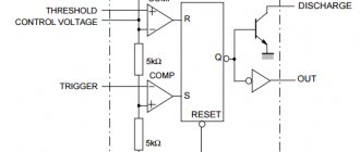
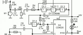
Let's move on to the principle of operation of the circuit
After power is applied, the R1–C3 chain generates a starting pulse with a duration of approximately 100 ms for the DD1 microcircuit, from which the OUT output of the microcircuit is set to log.1, thereby turning on the optosimistor VS1, the triac VS2 and connecting the load to the 220V network. From this moment the countdown begins.
The delay time of the timer is set by the chain R3–R6–C2. The charging time of capacitor C2 to the shutdown voltage, the output OUT of the DD1 microcircuit to logical 0 is determined by the formula:
t = 1.1*(R3+R6)*C2
Resistor R6 limits the minimum delay time to 3 seconds. Capacitor C1 is necessary to filter noise in the power supply of the DD1 chip and should be located as close to it as possible.
Resistor R4 sets the LED current of the optosimistor and when using MOC3043 analogues, for example MOC3042 or MOC3041, it should be reduced, since they require more current to operate.
This scheme
can also be used for switching starters, but keep in mind that in cases of low current starters, false operation or their buzzing in off mode is possible, since they can be switched on through the R5–C5 chain. In this case, this chain requires correction according to denominations.
Please note that the part of the circuit responsible for obtaining a constant voltage of 12 V can be replaced with a ready-made power supply (power adapter) with an output voltage of 12 V.
Such a device can be purchased immediately ready-made, or you can use an unnecessary one from any device: router, modem, phone or the like. In this case, the relay design will be significantly simplified.
Transformer T1 can be replaced with any other one with a rated input voltage of 220 Volts and an output voltage of 12 Volts.
If the switch-off delay relay circuit
you are interested and would like to download a file with an image of a printed circuit board - leave your comments.
Delays
The simplest time function from the point of view of use is the delay, we have two of them:
- delay(time) – “pauses” code execution for time milliseconds. Code execution does not proceed beyond the delay() function, with the exception of interrupts . It is recommended to use only in the most extreme cases or in cases where delay does not affect the speed of the device. time takes an unsigned long data type and can pause execution for anywhere from 1 ms to ~50 days (4,294,967,295 milliseconds) with a resolution of 1 millisecond. Works on the system timer Timer 0, so it does not work inside an interrupt or when interrupts are disabled.
- delayMicroseconds(time) – Analogous to delay(), pauses code execution for a period of time microseconds. time takes an unsigned int data type and can pause execution for 4 to 16383 µs with a resolution of 4 µs. Important: delayMicroseconds does not work on a timer, like other time functions in Arduino, but on a count of processor cycles. It follows that delayMicroseconds can work in an interrupt and when interrupts are disabled.
Delays are very easy to use:
void setup() {} void loop() { // do something delay(500); // wait half a second }
And now we can do some action twice per second. delayMicroseconds() sometimes does not work quite correctly with variables; you should try to use constants (const or just a number). To create microsecond delays with a variable period and work correctly in cycles, it is better to use the following construction:
// homemade microseconds delay function void myDelayMicroseconds(uint32_t us) { uint32_t tmr = micros(); while (micros() - tmr < us); }
But what if we need to perform one action twice per second, and another three times? And the third - 10 times per second for example. We immediately get used to the idea that it is better not to use delays at all in real code. Maybe delayMicroseconds(), it is sometimes needed to generate some kind of communication protocols. A normal tool for time management of your code are functions that count the time from the start of the MK.
yield() function
The Arduino developers made sure that the delay() function not only blocks code from executing, but also allows other code to execute during this delay. This “crutch” is called yield() and works as follows: if you declare a function
void yield() { // your code }
then the code located inside it will be executed while any delay() delay is running in the program! This solution, although it seems ridiculous, at the same time allows you to quickly and without describing unnecessary crutches and timers to implement a couple of parallel tasks. Which is fully consistent with the purpose of Arduino - the simplest and fastest development of a prototype. Consider, for example, this simple example: a standard flashing LED, but with button polling
void setup() { pinMode(13, OUTPUT); } void loop() { digitalWrite(13, 1); delay(1000); digitalWrite(13, 0); delay(1000); } void yield() { // and here you can poll the button // and not miss clicks due to delay! }
We will look in more detail about how to work with yield() and build a program based on it in one of the following lessons on how to write a sketch.
Video on the topic
Post navigation
"Installing a circulation pump in the heating system. Connecting a humidity sensor to Arduino"
Time relay with switch-off delay
Date: March 03, 2021 | Section: Works from readers
Hello, dear readers of the site sesaga.ru. After reading an article about a time relay with a turn-on delay, I tried to assemble a relay circuit with a turn-off delay for a fan in the toilet and I did not like the transformerless power supply circuit with two diodes and a quenching capacitor used in the article. Since the circuit turned out to be very power-hungry and consumed quite a lot of current for its own power supply, I installed a diode bridge, which allowed me to reduce the power consumption to 10 W (the total power consumption of the time relay depends on the type of relay used).
Attention! This design has transformerless AC power supply. When assembling it, pay special attention to compliance with safety precautions when working with electrical installations
.
The operating principle of a time relay is simple. When closing the contacts of button S1
(without latching) power is supplied to the circuit through a transformerless power supply and the NE555 timer is turned on.
Transistor VT1
, relay
KL1
and blocks the contacts of button
S1
, leaving power to the time relay circuit and the fan turned on for the duration of the specified shutdown delay.
As capacitor C3
to a level equal to 23 supply voltage, the timer will switch to the off state, relay
KL1
will de-energize and with its contacts
KL1.1
will disconnect the circuit and the fan from the network. This ensures zero current consumption in standby mode.
In general, the time relay works perfectly and does not consume current when it is off. I drew the signet in lay format based on the available details. To connect the wires, I used a self-clamping connector from a burnt-out fluorescent lamp ballast such as 2x36 electronic ballasts and the like, which is very convenient when installing low-current circuits, the main thing is quickly. Timer 555 is used in an SMD case, and the S1 button is taken from an apartment bell.
The archive of the printed circuit board in lay format can be downloaded here
link.
I wish you success in repeating the design! See you! Yuri, Vitebsk.
If you liked the article, share it with your friends:
Multifunctional relay devices
You can also assemble multifunctional relay devices with your own hands, which can be used in the household. They can be used to control heating, ventilation and lighting on and off. Multifunctional devices can operate at any specified time intervals. The delay can be adjusted in the range from 0.1 sec to 24 days, while the supply voltage can be from 12 to 220 V AC or DC.
The main functions of the relay in such cases are considered:
- Switch-off delay due to switching contacts;
- Device response delay.
You can activate and deactivate household appliances without the presence and participation of the user. Most models produced these days are equipped with a time relay for automatic start/stop.
What to do if you want to manage outdated equipment in the same way? Be patient, take our advice and make a time relay with your own hands - believe me, this homemade product will be used in the household.
We are ready to help you implement an interesting idea and try your hand at becoming an independent electrical engineer. For you, we have found and systematized all the valuable information about the options and methods of making relays. Using the information provided will ensure easy assembly and excellent performance of the device.
The article proposed for study examines in detail the self-made versions of the device that have been tested in practice. The information is based on the experience of craftsmen passionate about electrical engineering and the requirements of regulations.
Triac time relay circuits
Schemes that allow you to directly (without a relay) control the disconnection of the network load are shown in Fig. 3 and 4. They use a triac as a switch. Compared to the original, in the options presented here, some ratings have been changed to allow devices to operate on 220 V mains voltage.
In the diagram in Fig. 3, the load is turned on immediately when contacts SA1 are closed, and turned off with a delay determined by the ratings R2-C2 (for those indicated in the diagram it is 11 seconds). Circuit R1-C1 ensures that the one-shot device starts when turned on.
Rice. 3. Transformerless network load control circuit.
Rice. 4. Scheme option for automatically disconnecting the network load.
In the second scheme (Fig. 4), the load will be turned on when initially connecting to the network or when pressing the SB1 button. To power the microcircuit, a reactance is used, which is capacitor C1 (it does not heat up, which is better compared to a voltage-damping active resistance, as was done in the previous circuit).
Zener diode VD1 provides a stable supply voltage to the microcircuit, and diode VD3 allows you to reduce the readiness time of the circuit for frequent pressing of the button. The turn-off delay time can be adjusted by resistor R3 from 0 to 8.5 minutes. The timing capacitor SZ must have a small leakage.
Literature: For radio amateurs: useful diagrams, Book 5. Shelestov I.P.
Content:
Both in everyday life and in production, there is a need to turn off electricity consumers after a given period of time. To break an electrical circuit, you need either a contact or a controlled semiconductor device. And to form a given period of time, you will need either a stopwatch or a timer. It all depends on the direction in which the time count is taken.
The stopwatch adds seconds, and the timer subtracts. The only difference is this. But the time interval, if given, is the same for both. And the contact or semiconductor device for switching is part of a relay - electromechanical or semiconductor. If we combine a relay with a timer or stopwatch, we get a time relay (RT). Below we will talk about this device in more detail.