Published: 06/18/2016 Category: Electrical Views: 4462
Country cottage at the finishing stage, the cable has already been installed “for automation”
Repair and construction work should always be carried out with reference to the future. Further plans for the arrangement of housing, the type and quantity of equipment used, the possibility of simply changing the parameters of the premises due to new circumstances (for example, the birth of a child) - all this is taken into account in advance, even at the project stage, thereby saving time and money. To a large extent, this applies to private country houses.
“Smart Home” is an intelligent control system that integrates utility networks and electrical equipment of the house. In recent years, “smart home” systems have been on everyone’s lips – when conducting communications in a cottage, the owner is increasingly considering the possibility of adding automation functions. It is convenient, modern, saves energy resources and provides a high level of security. However, the implementation of such a system is not limited to the banal purchase and installation of individual smart devices. A kettle or toaster with smart functions is good on its own. But it's about more than that.
It is recommended to make a “Smart Home” project for a house or large apartment based on a “wired” home automation system. Such a system implies the presence of specific electrical wiring through which all engineering systems, electrical appliances, video cameras, sensors are connected into a single network. Therefore, its successful implementation should also begin and be thought out in detail at the stage of construction or major renovation of a building.
This does not mean that a “smart” system cannot be installed at all without gating the walls in a house with classic electrical wiring. For this purpose, there are separate smart devices and wireless solutions that allow you to connect them into a single network, but with a large number of devices and a large area where they are located, wireless solutions can be unstable. The functionality of such a “lightweight” system will lag significantly behind that of a full-fledged “wired” smart home.
What is such an electrical network? What are its advantages? Is this really beneficial and what should be taken into account for the best result?
What does electrical wiring look like in the Smart Home system?
It’s worth mentioning right away that in order to install electrical wiring for a Smart Home, a detailed project is required - as-built documentation for cable installation, which indicates the location of the cable, diagrams of electrical panels and “bindings” of all elements. Often, with classical electrician, the electrician decides how to organize the electrical wiring. In a Smart Home, all decisions are made at the design stage, and installation occurs strictly according to the project.
The smart home project contains complete working documentation for electrical installation
From the point of view of electrical protection, the Smart Home project has all the usual attributes of modern classical wiring: RCDs, automatic circuit breakers, automatic circuit breakers. Regarding the connection of final equipment with switches, there is one important nuance. In a simple electrical network, any device, say a light bulb or a group of them, is directly connected by a power cable to a switch. By interrupting or completing the circuit, it turns the light on or off. A more complex implementation may use multiple control elements to enable tripping from different locations. But the essence remains the same. One wire goes through the switch (or through each of them, if there are several) to the light bulb.
Visual representation of a classic electrical circuit
In contrast, in the Smart Home project, the wire system involves the use of two types of lines:
- power (220 Volts for powering electrical equipment);
- informational (low current).
Each of these cables (one from the device, and the other from the switch) is connected to the electrical panel in which the automation system modules are located. The signal from the switch via a low-current data wire reaches the controllers located in the panel. They process this signal and supply power to electrical equipment via the second wire, the power wire. Thus, in a “smart” system, control of devices occurs indirectly - through controllers. Their operating logic can be programmed as needed, for example, to turn on the lighting immediately, with a delay, or based on a signal from a sensor. This achieves the required level of automation.
In an automation system, loads are connected not through switches, but directly into the switchboard
Lighting cables in the Smart Home
A light group is several light bulbs or other lighting fixtures that can only be turned on at the same time. That is, they mean one switch key. A two-arm chandelier means two groups of light. Two sconces on the wall that work only at the same time - one group of light.
For all light groups controlled from the controller, the cable is routed according to the “star” system - a separate cable for each light group. All cables are connected to the central panel of the automated control system or main switchboard (depending on where the relays will be installed). You can come up with some kind of intermediate shields, such as floor shields, but I usually do not recommend such a distributed system.
Classically, a 3x1.5 cable is installed for lighting, usually VVGng(A)-LS 3x1.5. This allows you to connect a high-power light group, connect luminaires with grounding, or use the third cable core to divide the light group into two. At your request, you can use a two-core cable or a more convenient flexible cable (for example, KGVVng), it is only important that it is suitable for stationary installation (not PVS or ShVVP). But remember that according to building codes, a cable with a cross-section of 1.5mm2 must be installed for lighting.
A relay in the panel supplies power to the lighting group or removes voltage from the group. It could be 230 volts, or it could be another voltage.
When controlling an LED strip, there are two options:
- Power supply near the tape. In this case, the relay supplies 230 volts to the power supply, which turns on the tape. Cable minimum 2x0.75 for a unit without a grounding terminal (in a plastic case) or minimum 3x0.75 for a unit with a grounding terminal (in a metal case)
- Power supply in the shield. In this case, the relay switches not 230 volts, but 12 or 24 to the tape. But you need to make sure that the distance from the block to the tape does not lead to a voltage drop in the cable (it must be counted). Depending on the current that will flow through the cable from the block to the tape, and on its length, a cable with a cross-section of 0.75 to 4 mm2 may be required.
Here is an article about options for placing power supplies.
To control an RGB (three-color) LED strip or RGBW (three colors + white), more cores are needed in the cable. RGBW tape - 5 cores (4 colors and a common plus). Cross section - depending on the current flowing through the cable.
What are the benefits and benefits of smart wiring?
The obvious benefit of using such wiring in a Smart Home project is the possibility of automation and ease of control of any number of different devices (by devices here we mean lamps, motorized curtains, air conditioners, AV equipment, and the like). There is also something else.
At first glance, it may seem that the implementation of a Smart Home project will require several times more cable than for classical wiring. But this is not true for two reasons:
- a low-current information cable (bus) passes through all the switches of the house, connecting them with the automation modules in the panel - thus, its length depends more on the size of the room than on the number of lamps, sensors and other devices (but with the selected star topology, all it will be the other way around).
- the power wire passes from the panel to each device or group of devices, bypassing the switches responsible for their operation, so its length is less than the length of the same cable with classical wiring.
Thus, “smart” electrical wiring is a completely rational solution that does not require an unreasonably large number of power and information cables . In some ways, it is simpler because there are no power wire “loops” from the panel to the switch, and then to the chandelier or other devices. The information bus is the same for all Smart Home devices.
There remains one important question that needs to be answered if you want to create your own Smart Home project: “What type of information cable (bus) should I use and what will be the geometry of its connection to numerous devices?”
Dimming light in a Smart Home
Dimming (brightness control) of a group of lights can be done in the following ways:
- Trimming a sinusoid (TRIAC). Incandescent and halogen lamps, as well as some LED lamps, are dimmed this way. In this case, a dimmer is installed in the panel instead of a relay.
- Control voltage 0-10 volts (or 1-10 volts). In this case, the light group must be supplied with a constant supply voltage of 230 volts + an additional category 5 FTP cable along the power cable, through which the control voltage is transmitted from the controller’s analog output module. In this case, 220 volts can be distributed sequentially with one line to all groups of light, but for reliability it is recommended to use the same “star” circuit (in case of replacing lamps with non-dimmable ones or with a different control method). This is how LED lamps are dimmed.
- DALI. This is a light control protocol; to use it, luminaires must be equipped with DALI drivers. We supply power to all lamps (phase, neutral, ground) and two DALI bus wires. The DALI bus does not necessarily have to go over twisted pair; you can install a 5x0.75 or thicker cable for light (three wires for power supply, 2 wires for bus). You can pull a separate power cable, a separate twisted pair cable or an ES-04. The DALI bus cable can go in a star to all lamps (a separate cable from the switchboard for each one), or it can go through everything in a loop. This method is justified if there are very large (more than 40-50) lighting groups, but connecting with a cable is not universal due to the fact that subsequently it will not be possible to refuse control via DMX or DALI.
To dim the LED strip, special PWM dimmers with a control voltage of 0-10 volts (or 1-10 volts) are used. In this case, you need to supply the dimmer with the tape supply voltage (12 or 24 volts) + a control signal from the controller. The dimmer can be located directly next to the tape, or maybe in the shield.
Type and topology of the information bus of intelligent systems
Fundamental in this matter will be two factors, on which it will depend on what type of tire to include in the project, and what configuration should be followed when laying it:
- Today there are a large number of manufacturers offering their automation protocols. Creston, KNX, HDL, Teletask, Vantage - this is not a complete list of everything that is available on the smart systems market. Internet, television, and telephony use different wires, depending on the service provider and other factors. Likewise, most automation protocols require their own type of information bus, which must be taken into account at the design stage.
- Exactly how the wires are laid - the network topology - will depend on the type of system being implemented. There is a concept of decentralized systems, each element of which has intelligent functions for processing incoming signals. In such a “Smart Home” there is no need to send command streams to the central processor. In another case, signals from all switches must first be sent to the “heart” of the system, and only then to the actuators.
In some situations, the same type of system from different manufacturers (for example, decentralized from HDL and KNX) may have the same cabling. As for the use of open standards (for example, KNX type), there is no need to change the cable geometry when using equipment from other manufacturers.
Although all this should be taken into account at the stage of creating a Smart Home project, this is not a limitation in the use of “hybrid” systems - when different automation protocols or equipment from different manufacturers are used. Sometimes this may be the best solution to get maximum efficiency. Everything just needs to be planned in advance.
The KNX automation protocol supports various communication media, including IP and radio. But most often a special wired bus is used, to which all equipment is connected. The device connection geometry can look like:
- lines;
- wood;
- stars.
It is possible to combine these types. One segment, which is the simplest element of the topology, includes up to 64 nodes. The maximum number of segments combined into one line is four. Up to 15 lines are combined into one area. In turn, up to 15 areas can be combined at the top level of the system. Thus, the size of the system is calculated by the number of possible devices, equal to: 64 nodes * 4 segments * 15 lines * 15 areas = 57600 pieces.
As for the size of the premises in which a Smart Home project can be implemented, they can be quite large, since KNX smart wiring has a maximum distance between instances of connected equipment - up to 700 m, and the cable length in a segment - up to 1000 m.
The Smart Home system implies a special rational option for laying cable routes , which uses an intermediate link (between the control element and equipment) in the form of logical controllers. To maintain the operation and efficient functioning of such a network, other devices are used, depending on the need. Wiring methods will depend on the automation protocol vendor, its type (centralized or decentralized), and the need to use equipment from other manufacturers.
To take into account all these points and outline the concept of the future system for yourself, it is best to discuss these issues with a company that is a Smart Home integrator at the very early stage of a major renovation or construction of a house. Then your building will be fully prepared to not only become “smart” now, but also to easily adapt to changing conditions that require adding, removing or reconfiguring smart devices.
These articles may also be of interest to you:
- Electrical connection diagrams
- Electrical boxes
- Wire routing
- Lighting of a summer cottage
Alarm sensors in a Smart Home
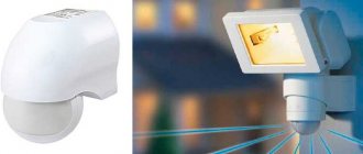
Motion sensors
can be used for security alarm functions and light control by motion detection. A four-core unshielded CQR 4x0.22mm cable is installed before the motion sensors. Two wires of the cable are used to transmit power to the sensor 12 or 24 volts, two wires are the sensor response signal (closed in normal condition, open in case of alarm).
Motion sensors are usually placed in the corner of the room in order to capture the largest area. Standard detection range is 8-12 meters, angle 90-120 degrees.
There are circular sensors with a detection angle of 360 degrees, a range of 8-12 meters. Located in the center of the room.
Motion sensors of the “curtain” type monitor the area strictly below them and are installed on the windows on the side of the room or above the doors.
Corridor-type motion sensors have a detection range of up to 25 meters, the width of the corridor is about 2 meters.
Door/window sensors
(reed switches) are connected with the same cable. They do not require power, they simply open the loop when triggered.
Gas sensors
connected in the same way with the same cable. For sensors with a supply voltage of 230 volts, an additional power cable MKSh 2x0.75 or similar must be provided. For gas sensors with combined sensors (for example, natural + carbon monoxide), it is necessary to provide cables based on power supply (2 wires) + 2 wires for each relay output signal of the sensor.
The natural (main) gas and methane sensor is installed at a distance of 5-15 cm from the ceiling, no further than two meters from the gas source.
The liquefied gas sensor (propane, butane - gas in cylinders) is installed at a distance of 15-25 cm from the floor, no further than two meters from the gas source.
The carbon monoxide sensor is installed at a distance of 1.5 meters from the floor, no further than 1.85 m from the gas source. The source of carbon monoxide is a wood fireplace.
Sensors of the same type can be connected in one loop (connect all sensors with one cable), this will save cable, but the panel will not know which sensor was triggered.
Smoke detectors
can be connected with the same CQR 4x0.22mm cable, if fire alarm approval is not required in any authorities. If approval is required (for commercial premises), then fire-resistant FRLS cable must be used in accordance with the fire alarm design.
Benefits of wired technology
Today this technology is the most reliable and fastest. It has almost unlimited possibilities for system expansion and has good network security. In addition, wired technology does not depend on the operation of autonomous power supplies, since it does not use them. It also allows you to see the status of all devices, because all devices in the system interact with each other online, and this communication does not depend on the power source or the distance between them. For example, if you activated some command, for example, turned on the central chandelier in the living room, then on the touch panel we will immediately see that the chandelier in the living room is turned on. This is called displaying command statuses. Such statuses are displayed on iPad, iPhone, other touch panels and local switches, because it is very important to know what is currently happening in the house. This is one of the main advantages of a “Smart Home”: if you know whether the lights are turned off everywhere and whether the windows are closed, then there is no need to make rounds around the house to check its condition.
Smart homes are different. Legrand has the most necessary
The definition refers to different systems and a set of devices.
Sometimes this is a set of household appliances, when the TV turns on when someone is in the room, and the refrigerator monitors the contents of food.
In other cases, entire security services are created, when several sensors react to the presence of people in the house, monitor leaks and open doors.
There is a third option, the most basic and closest to all of us. Legrand decided not to take on refrigerators and routers that were unfamiliar to them, but brought to the 2021 level what they are always good at: electrics.
Therefore, the company thought of a system that would not clutter the interior with strange gadgets, and its installation has long been clear to everyone.
At the same time, Legrand plans to develop an ecosystem with smart motion sensors, CCTV cameras and much more closer to 2021. But we started with solutions that everyone can have.
In terms of design, there are several options to choose from: the strict Valena Life with Netatmo, the streamlined Valena Allure with Netatmo or the elegant Celiane with Netatmo (four in total), so such elements will be appropriate in an apartment with any decor. From minimalism to classics.
We tested several modules, including a smart plug and light. We took it over and tried integrating devices at home.
