Preparation: continuity testing and phase determination on the ceiling
Those who have at least a little knowledge of electrical networks will not need this, others will find it useful. It can be difficult for a person who does not constantly deal with electricity to navigate. To avoid confusion, we will tell you everything in order: how to find phase (or phases) and zero in the wires on the ceiling, what to do with grounding. And then, like a whole bunch of wires on a chandelier, connect them to those that stick out above. As a result, connecting the chandelier with your own hands will be a simple task for you.
Ground wire
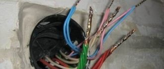
If the wiring is already done, there will be two, three or four wires sticking out from the ceiling. One of them is definitely “zero”, the rest are phase, and there may also be grounding.
There is a grounding wire in houses that are newly built or recently renovated.
There is not always a grounding wire, only in newly built houses or after major renovations with replacement of electrical wiring. According to the standard, it has a yellow-green color and is connected to the same wire on the chandelier. If your chandelier does not have one, carefully insulate the exposed wire and leave it as is. You cannot leave it uninsulated - you may accidentally short-circuit it.
Looking for phases and zero
You need to figure out the rest of the wires: where is the “phase” and where is the “zero”. In older houses, all wires are usually the same color. Most often - black. New buildings may have black and blue, or brown and blue. Sometimes red is present. In order not to guess by colors, it is easier to ring them.
If you have three wires on the ceiling, and a two-key switch on the wall, you should have two “phases” - for each of the keys and one “zero” - the common wire. You can ring with a multimeter (tester) or an indicator screwdriver (this is a special screwdriver with a light that lights up when voltage is present). During operation, move the switch key to the “on” position (the input circuit breaker on the panel is also turned on). After dialing, turn the switch keys to the “off” position. If possible, it is better to turn off the circuit breaker on the panel and connect the chandelier with the power turned off.
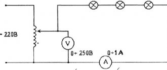
Checking the wires on the ceiling with a tamper
How to ring and identify wires with a tester is shown in the photo. Set the switch to the “volts” position, select the scale (more than 220 V). Alternately touch the pairs of wires with the probes (hold the probes by the handles, do not touch the exposed conductors). The two phases do not “ring” with each other - there will be no changes on the indicator. If you find such a pair, most likely there are two phases. The third wire is most likely “zero”. Now connect each of the proposed phases with probes to zero. The indicator should show 220 V. You found zero - in the international specification it is designated by the letter N - and two phases - designated L. If all the wires are the same color, mark them somehow: with paint, a colored marker, a piece of adhesive tape. Phases are in one color, zero is in another.
It is easier to work with an indicator screwdriver: just touch its end to the exposed conductor. Lit - phase, no - zero. Very simple.
Using an indicator screwdriver to find a phase
If there are only two wires sticking out, then one of them is phase, the other is zero. In this case, there is only one key on the switch. There are no other options.
Read about the rules and methods for connecting wires in a junction box here.
General requirements and safety
Before you start working with the electrical network, you need to familiarize yourself with the basic safety requirements. Knowing these points will not only help prevent possible injuries, but will also help reduce the risk of damage to conductors or switch mechanisms to zero.
Basic safety requirements:
- the handles of all tools used in working with electrical wiring must be insulated;
- during the period of manipulation, the electricity in the entire room must be turned off by turning the toggle switch on the panel (if it is absent, the plugs are unscrewed);
- Installation of a double lamp switch is carried out in the “phase” wire break.
It must be remembered that at the time of inspection of the connected circuit, switching on and off can only be done with final fixation of the wires and their high-quality insulation.
Wires on the chandelier
Connecting a chandelier with 2 wires is simple: screw one of them to phase, the other to zero. Which one goes where - it doesn’t matter. If there are two phases on the ceiling, and the switch on the wall is two-key, there are options:
- Twist the phases together and connect one of the wires from the chandelier to them. In this case, to turn it off, you will have to turn both keys to the “off” position, and the lighting will turn on from any of them.
- Connect the wire to one of the phases and insulate the second. Then only one key will be working. The second is to be empty.
How to connect a chandelier if it only has two wires? To the same wires on the ceiling in random order
On multi-arm chandeliers there are definitely more than two wires. We have decided on the purpose of yellow-green. This is grounding. If the same wire is on the ceiling, connect it to it. The rest also need to be dealt with.
A chandelier with 3 wires is not much more difficult to connect. If one of them is grounding (yellow-green), it can be:
- ignore - if there is no wire of that color (or similar) on the ceiling,
- connect to one of the same color.
Actually, there are no other options. Three wires are mainly used for lamps with one bulb. With two, this is an outdated design, with three, a more modern design that complies with current recommendations.
Connection to double switch
They connect a five-, four-, three-arm chandelier to a two-key switch according to the same principle. From each of the horns there are two different colored wires. Most often these are blue and brown wires, but there are other variations. To connect to a double switch, they all need to be divided into three groups: two phases and one zero.
Connecting a five-arm chandelier to a double (two-key) switch
First, all the blue wires are combined with each other and twisted well. This is zero. In principle, you can take wires of a different color - it doesn’t matter for lighting fixtures. But according to the standard, “zero” is indicated in blue. It is only important that conductors painted in a different color do not get into the twist. In the photo below you see that all blue conductors are combined into one group. This is “zero”.
Before connecting the chandelier, the conductors are grouped
Now divide the remaining ones into two groups. The breakdown is arbitrary. One group of light bulbs will turn on from one key, the second - from another. A five-arm chandelier usually combines 2+3, but 1+4 is also possible. The four-arm version also has two options - 2+2 or 1+3. But with three light bulbs there are no options: 1+2. Twist the separated wires together. We received two groups, which we connected to the “phases” on the ceiling.
How to connect a chandelier to a single switch
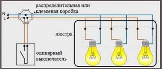
If there are only two wires on the ceiling, but there are many on the chandelier, but only in two colors, everything is simple. Twist all the conductors of the same color with their bare parts and connect them to one of the wires on the ceiling (it doesn’t matter which). Collect all the conductors of the second color into one bundle and connect them to the second ceiling one. The chandelier connection diagram in this case is shown in the figure below.
Connection diagram of a chandelier to a single-key switch
When turned on in this way, all the lights will light up at the same time.
A little theory
A procedure such as installing and connecting a chandelier requires certain knowledge about the switches and wires that you will have to work with.
Connecting a chandelier to a double switch, rather than to a single-key switch, is inherent in the design of the lighting fixture itself. Three wires (with painted or white insulation) coming from the ceiling also indicate this.
A bundle of multi-colored wires, including those coming from the purchased chandelier, carries certain information.
In the EU, color marking of wires is established by the IEC 60445 standard of 2010, in the Russian Federation - by GOST R 50462 of 2009. She looks like this.
The wiring of the electrical network with cables for domestic premises of the NYM, VVG, VVGng (non-flammable) brands in a modern private house also complies with these standards. If this is not the case, then the network needs to be called - to determine the purpose of the cores of a two- or three-wire wire.
This is done using a screwdriver with a phase indicator light. The phase conductor lights up the LED in the screwdriver. Recording the result with a colored permanent marker or colored electrical tape is mandatory.
For lighting, a cable with 3 conductors with a cross section of 1.5 mm2 is laid. The cross-section of the neutral and phase conductors must be the same. Advantage is given to copper wires: they have greater electrical conductivity, do not oxidize, are durable, and flexible. If before connecting a new chandelier it is possible to replace the aluminum wiring with copper, it is worth doing.
The maximum power of the lighting device should not exceed the value indicated in the table. Information is contained in the instructions for the chandelier, the presence of which is required.
A safety margin (subtract 20% from the received power) will not hurt. The goal is to insure against wires of smaller cross-section and low-quality copper. With old wiring, such caution is more than justified.
You also have to connect the wires (of the same metal) coming out of the ceiling with the wires of the chandelier. Conventional twisting using pliers is not even considered (prohibited by clause 2.1.21 of the PUE). Working with a soldering iron under the ceiling is a dubious pleasure, and not everyone can do it.
The owner of a private house must have blocks, PPE, NShVI tips, a clipper or self-clamping terminals.
When an aluminum wire comes from the ceiling, and a copper wire comes from the chandelier, they should be connected only using terminal blocks, walnut clamps or WAGO self-clamping terminals with Alu-plus paste.
In the future, the word “connect” means just such a connection of wires to each other. Of course, all work with devices and wires must be done with the network turned off in the room.
Subtotal: we have theoretical information, modern materials, and tools.
Rules for connecting wires
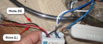
There are no small details when working with electricity. Therefore, we connect the wires in the chandelier according to all the rules. When combined into one group, it is not enough to simply twist them and screw on the protective cap.
You need to connect the wires from the chandelier and the switch in the terminal box
Such twist will sooner or later oxidize and begin to heat up. It is highly advisable to solder such connections. If you know how to handle a soldering iron and tin, definitely do this. This will guarantee normal contact and the connection will not heat up.
Now let's talk about how to connect the wires from the chandelier with the wires from the switch (which are on the ceiling). According to the latest rules, twists are not allowed. Terminal boxes must be used. Most modern chandeliers are equipped with them. If not, buy it at any hardware store or retailer of lighting fixtures.
When using such a terminal box, a problem arises: a twist of a large number of wires simply does not fit into the hole. Output: solder a conductor to the connection (copper, single-core or stranded, with a cross-section of at least 0.5 mm2). This connection is well insulated, and the free end of the soldered conductor is inserted into the terminal box (a long one is not needed - 10 cm is more than enough).
Having inserted all the wires from the chandelier into the terminal block and tightened the screws, the entire structure is raised to the ceiling. There it is pre-fixed, after which the wires are connected to the terminal block in the required order. In this case, it is important to set “zeros” one opposite the other. Phases are connected to phases in random order.
The correct connection of wires in the junction box is described here.
How the wires on the chandelier are separated, how the conductor and the chandelier are connected to the terminal block - all this is in the video.
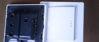
Types of two-key switches
Any switch with two keys has three contacts. One on top, two on bottom.
The switch can be with or without backlit keys. In the first case, when using LED, energy-saving lamps, they may blink during operation or glow slightly when turned off.
Recently, LED lamps have appeared that are specifically designed for such switches. But their price is quite high due to the more complex electronic circuit. It's cheaper to replace the switch.
If lighting is vitally important on a limited budget, you will have to use one incandescent lamp of any power in the chandelier.
Connecting a Chinese chandelier
Most of the relatively inexpensive chandeliers on the market come from China. What's good about them is their large assortment, but there are problems with the quality of the electrical assembly. Therefore, before connecting the chandelier, you need to check its electrical characteristics.
First, check the integrity of the insulation. They can be assembled into one bundle and short-circuited to the housing. The tester should not show anything. If there are any indications, you have two options: look for and replace the damaged wire or take it for an exchange.
The second stage of testing is checking each horn. There are two wires coming from the horn. They are soldered in a cartridge to two contacts. Connect each wire to the corresponding contact. The device must show a short circuit (short circuit or infinity sign, depending on the model).
After checking, start grouping the wires as described above.
The most common mistakes in connecting a chandelier
Errors during installation and connection occur not only among novice electricians; even among experienced specialists, it often happens that the chandelier does not shine at all the way it should. These mistakes are typical and banal.
If the number of wires in the chandelier and on the ceiling do not match
It may turn out that the chandelier you purchased has three wires, but there are only two wires on the ceiling where the chandelier is mounted, and the switch, accordingly, is single. Or vice versa. The algorithm for connecting a three-arm chandelier to a single switch looks like this:
- Connect the neutral wire of the chandelier to the neutral wire on the ceiling.
- In the terminal block of the chandelier, install a jumper between the phase wires or clamp them in one terminal and connect them to the phase wire on the ceiling.
With this connection scheme, it will no longer be possible to regulate the light level.
In the opposite situation, when the home electrical wiring has three wires (two phase and one neutral) and a double switch, and the chandelier has only two wires, the connection is made in the following sequence:
- Using a voltage indicator, you need to determine the neutral wire and connect it to any of the wires on the chandelier.
- Clamp the other two wires (phase) into one terminal, or install a jumper.
Incorrect connection of double switch
This is the most common mistake, which consists in connecting the incoming phase wire to one of the output contacts of the switch. With such a connection scheme, the chandelier cannot function normally, since one section of the lamps turns on only if voltage is applied to the other section.
That is, if the incoming phase is connected to the left contact of the switch, when the left key is pressed, the phase enters the distribution box through the lower input contact and turns on one section of the lamps. The next time you press the right key, another section is turned on. But when you open the left key, all sections are turned off.
When the left key is pressed, it is impossible to turn on the right key.
The reason for the dependence of the right key on the left is that initially the phase entered through the input contact of the left key switch, and the left key, when turned off, breaks the phase in both sections at once.
To eliminate this error, you should swap the connections of the incoming and outgoing phases of the switch.
Instead of a phase wire, a neutral wire passes through the switch
According to the rules of electrical installations, there is a procedure for connecting a switch that closes and opens the circuit by breaking the phase. How does it look on the diagram? The neutral wire, bypassing the switch, is laid from the distribution box directly to the neutral wire of the ceiling lamp. The phase wire from the junction box passes through the switch key, which breaks the circuit.
However, in practice, sometimes an incorrect connection occurs: it is not the phase wire that passes through the switch, but the neutral wire. That is, when the switch key is turned off, the electrical wiring remains energized, despite the fact that the lighting is not on. This is fraught with the possibility of electric shock when replacing a lamp, if you accidentally touch the exposed parts of the chandelier shade, or if the insulation of the wire is broken.
Therefore, if possible, it is advisable to eliminate such a connection error.
This violation of the connection diagram can be detected using a voltage indicator, which, when the switch is in the “off” state, shows the presence of a phase on the ceiling wires.
Incorrect connection diagram for the neutral wire of the chandelier
This error is the reason that only part of the light bulbs in the chandelier turn on normally, the rest either shine weakly or do not turn on at all. As previously discussed, if there are three wires, the phase wires are each connected to a separate section of light bulbs, while the neutral wire is common to all light bulbs, which are all connected to it in parallel.
If you mix up the wires and connect the interconnected light bulbs, say, of the first section to zero instead of the phase, and connect all the light bulbs of both sections to the phase (instead of zero), then when you press the first key in the first section, the light bulbs will turn on, since they go there at the same time both zero and phase.
When you press the second key in the second section, the light bulbs will not light, since both incoming wires will be phase, and in order for the light bulb to shine, a phase with zero must be supplied to it at the same time.
Connecting a halogen chandelier (with and without remote control)
Halogen lamps operate not from 220 V, but from 12 V or 24 V. Therefore, step-down transformers are installed in each of them and the entire circuit is assembled and ready for installation. Only two conductors remain free, which need to be connected to the wires sticking out on the ceiling. It is connected in any order, “phase” and “zero” do not matter.
If the chandelier is equipped with a remote control, a control unit is added to the transformers. The connection is similar: there are two conductors that need to be connected to the one on the ceiling. The third conductor coming from the other side (it is thin) is an antenna, with the help of which the remote control and the control unit “communicate”. This conductor remains inside the glass in the form in which it is.
How to connect a chandelier with a remote control, see the following video.
Purpose of using a two-button switch
Assembling and connecting a chandelier with 2, 3, 4, 5 or more arms through a two-key switch aims to divide the lamps into 2 groups. This provides 3 operating modes:
- When both keys are turned on, all chandelier lamps work.
- When you turn on the right key, a group with fewer lamps works.
- When you turn on the left key, a group with a large number works.
This flexibility allows not only to save electricity, but also to create light comfort in the room that suits the situation.
How to connect a chandelier via a double switch
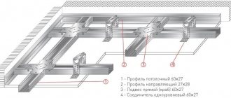
- 3- and 4-core cable VVGnG-Ls with a cross-section of 1.5 mm2
- two-gang switch
- pressed GSI sleeves in insulation
- Vago terminal clamps
First of all, take a three-core cable VVGnG-Ls 3*1.5mm2 and stretch it along the groove to the nearest junction box near the chandelier.
Leave some reserve in it for cutting and connecting the ends.
In the electrical panel, remove the insulation from the cable and connect the phase conductor (let it be conditionally white) to a single-pole circuit breaker.
Place the yellow-green and blue wires in the appropriate places (ground and neutral bars).
It is advisable to mark the stripped cable in the junction box so as not to confuse anything in the future.
Now, with another 3-core cable from the distribution box under the ceiling, to the mounting box below, where you will have a two-key switch, you need to make a lowering.
- L1 – phase for the first group of lamps in the chandelier
- L2 – phase to the second group of lamps in the chandelier
They need to be signed both on the switch below and in the top box.
Next you will need a 4-wire cable. It needs to be stretched from the top junction box to the installation location of the chandelier under the ceiling.
- L1 – phase wire for connecting the first half of the chandelier
- L2 – phase wire for connecting the second half of the chandelier
Now the most important thing. It all needs to be assembled correctly and connected together in the upper junction box.
In order not to confuse or make mistakes, the inscriptions made earlier will come in handy. With them, all switching is much simpler.
Take Wago terminals and simply connect the wires with the same markings.
After which the box can be closed.
Next, work on the two-key switch.
Lead the main power supply L to the common terminal of switch 1.
Usually it is separate, but not all manufacturers have this design. Be careful!
L1 and L2 are connected to the lower terminals 3,4.
Install the protective and decorative strips and go back up to the chandelier.
Here the question may arise: how can you find out which wires protruding from the chandelier are phase and which are neutral?
Especially if they are the same color. There can be 3,4,5 depending on the type of lamp and the number of its horns.
This is where a multimeter will come to the rescue. You need to call the wires below, when the chandelier is not yet suspended from the ceiling.
According to the rules, the zero should come to the threaded part of the socket and the light bulb (outer contacts), and the phase to the central contact pin.
Switch the multimeter to the continuity test or resistance measurement mode, and sequentially touch the wires and contact parts of the sockets on each lamp with the probes. You need to achieve a sound signal or find where the resistance is zero.
If there are several zero wires, twist them into one common one.
Proceed to direct connection. To facilitate the sequence, first connect the protective ground and the neutral conductor. To do this, use connecting sleeves.
Although Vago terminals can also be used here.
After connecting the ground and zero, it remains to power two phases. Select any of the cores and press the supply wires L1 and L2 with sleeves onto the two phase wires on the lamp.
All that remains is to fix the chandelier on the ceiling and check its functionality.
- two-core cable VVGnG-Ls 2*1.5mm2
- three-core cable VVGnG-Ls 3*1.5mm2
- Dimmer
- connecting sleeves
- Wago terminals
The initial stage of installing a 3-wire power cable from the panel to the distribution box is the same as in the previously considered option. The connection in the panel is again made to a single-pole circuit breaker.
- L – phase wire from the switchboard
- Chandelier - phase wire for connecting the chandelier itself
Read more: How to choose an ouzo and an automatic machine based on power
Next, from the junction box to the chandelier itself, you need to stretch a 3-core cable with a cross-section of 1.5 mm2.
After that, in the box using Vago clamps, connect the wires according to all the inscriptions.
Connect identically marked wires to each other.
Move to the dimmer at the bottom. Connect the main power phase that comes from the electrical panel (previously you labeled it as L) to the dimmer terminal labeled “L” or “phase”.
Clamp the other core labeled “Chandelier” under the screw with the dimmable load icon.
Next, install the dimmer and secure it in the box itself, installing decorative frames on top.
On the chandelier, the phase conductor labeled “Chandelier” is connected through a pressed sleeve to the supply wire of the lamp.
If you have several phase conductors coming out of the lamp (two, three, four arm chandeliers), then to connect the load through a dimmer, simply twist them into one common conductor.
All that remains is to connect zero and ground, apply voltage and check the functionality of the entire structure.
Each lampshade of a three-arm chandelier has a socket for screwing in a light bulb with two contacts - one for phase and one for zero. Phase wires are painted in different colors, and the neutral wire is most often blue.
Connecting a chandelier is done in the same way as with two light bulbs, only one of the keys turns on one lamp, and the other turns on two horns at once. If desired, the assignment of the keys can be changed. If turned on at the same time, all the lights light up at once.
To achieve the desired result, all actions should be performed according to a certain scheme. As usual, the neutral wires from each cartridge are combined in the center, and the phase conductors are divided into two groups. The chandelier wires are connected to the ceiling conductors when the voltage is turned off. The grounding connection is made if appropriate wires are available.
Requirements for connecting a light switch with one key
The first thing to think about is where to place the switch. It should be located in an accessible place, at a convenient height, so that both older and younger family members can reach it.
Placing the switch inside the cabinet is an original, purely Russian know-how. But this option is unlikely to be convenient for daily use.For a chandelier, it is logical to place the switching device at the entrance door to the room. If we are talking about a floor lamp or sconce, then such points should be located near the sofa or at the head of the bed.
Remember that installing switches in the bathroom is prohibited in principle, as well as in the sauna room. To protect your family members, install these devices in the hallway.
All connection options, and there are several of them, are united by one common element: the presence of a dynamic element that closes and opens the electrical circuit. And one more general rule: when installing a single-key switch, you should make sure that the phase line is opened, not the zero line. If this is not done, you can get a strong electric shock even when simply replacing a light bulb in a chandelier.
Single-key switch connection diagram
The easiest way to install external type switches. Simple instructions on how to connect a single-key light switch:
| Photo | Description of work |
| In the grooves prepared for installation, place a cable with three cores from the distribution panel to the box. Leave a small margin of wire length for connections. | |
| Strip the red or gray phase wire and connect it to the free terminal of the machine. | |
| Connect the blue wire to the zero bus. The brown-yellow wire goes to the ground bus. | |
| Mark the wire strands in the box, this will greatly facilitate further work. | |
| The switch should be installed in a convenient location. Open doors should not interfere with access to it. The distance from the floor is approximately one meter. | |
| Connect a two-wire wire from the box to the switch. Leave a spare wire for connection. | |
| Connect the gray (red) wire to the top terminal of the switch, the blue wire to the bottom. | |
| From the box, run another three-wire wire to the location of the chandelier. | |
| Release and strip the ends of the wire. Attach the lamp to the ceiling. | |
| Connect the gray and blue wires to the corresponding contacts on the lamp, and secure the ground wire to the metal body of the chandelier. | |
| Connect the wires of the corresponding color using self-clamping terminals. | |
| If your home's wiring does not have a ground channel or the light housing is not made of metal, your box will have fewer connections. | |
| Accordingly, the lamp will also not have a grounding wire on the body. | |
| Before connecting electricity, install the keys on the switch. |
After the work is completed, check the operation of the device. Connect the power supply to the panel and try turning the light on and off. If there is no smoke and the lights in the entire entrance do not go out, you succeeded. If it goes out and goes out, call an electrician you know before the neighbors figure out who caused the accident.