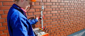
Carrying out electrical measurements when checking lightning protection: what is it, why is it needed and how is it done
Checking the condition of the lightning rod, the connection of the lightning rod with the down conductor and the down conductor with the lightning protection grounding circuit.
All work is completed in a short time. It is advisable to carry out a lightning protection check with the preparation of a “lightning protection check report” annually , before the start of a thunderstorm period.
Service from the company TM-Electro:
- Flexible pricing policy
- Guarantee of work quality
- Help in solving non-standard situations
- Constant feedback with the client
- Operational visit of engineers
- Own courier service
Lightning protection testing consists of:
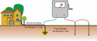
- ground loop testing
- measuring the transition resistance of lightning rods
Technical events
The list of necessary technical measures is determined by the person who allows the work together with the manufacturer in accordance with the requirements of SNiP 12-03-99.
When inspecting and checking the condition of lightning rods and down conductors on the roofs of buildings and structures, it is necessary to use installer safety belts. If the length of the belt sling is insufficient, it is necessary to use a safety rope previously secured to the building structure. In this case, one of the persons conducting the tests slowly lowers or tightens the safety rope. When checking welded joints of external current conductors and the design of lightning rods, the tool (hammer) must be tied to avoid falling. When a thunderstorm approaches, all work must be stopped and the team removed from the workplace.
What does the document include?
The protocol contains 3 components:
- Visual inspection data (Protocol No. 1)
- Checking transient resistance (Protocol No. 2)
- Checking the resistance of grounding devices (Protocol No. 3)
Also attached to it:
- lightning protection diagram indicating measurement points;
- copies of the registration (certification) certificate of the electrical laboratory;
- certificates of verification for the control and measuring instruments used to make the measurements;
- other necessary documents, if required (certificates, certifications of laboratory managers, engineers and others).
Visual control protocol No. 1
Contains the following items:
- Analysis of design documentation
- Checking the compliance of electrical installations (lightning protection part, down conductors, grounding conductors) with the regulatory framework and design. The presentation is performed in the form of a table.
- Found violations or comments
- Conclusion on acceptance or further operation of the lightning protection and grounding system
During the inspection it is recommended:
- visually assess the condition of all components, whether lightning rods and down conductors are damaged, whether they are securely connected to the system circuit, check the condition of all fasteners within the overall design of the lightning protection system;
- identify elements that require replacement or repair due to a violation of their mechanical strength;
- determine elements with corrosion, as well as the degree of its impact on the corresponding element;
- check the executive diagram of the lightning protection system with the current one;
- check the availability of the necessary documentation for lightning protection devices.
Protocol No. 2 for checking transient resistances
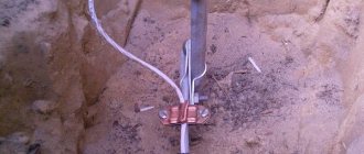
Measurements are performed in sequence from the lightning protection equipment to the grounding device, usually at the points where the connecting components (holders, terminals, etc.) are located between the individual components of the lightning protection system, as well as where it is in contact with the elements of the structure.
The results are recorded in the following table
The protocol also contains mandatory data:
- type of tests (acceptance, comparison, control tests, operational, for certification purposes);
- parameters of temperature, air humidity and pressure;
- data about the measuring device (type, serial number, metrological characteristics, verification dates, certificate number and the body that issued it).
Standardized values
Protection against direct lightning strikes of buildings and structures classified as Category I according to lightning protection devices must be carried out using free-standing rod or cable lightning rods
Protection from direct lightning strikes of buildings and structures classified as lightning protection categories II and III, with a non-metallic roof, must be carried out by separate rod or cable lightning rods or installed on the protected object.
When the roof slope is no more than 1:8, a lightning rod can be used as a lightning rod, made of steel wire with a diameter of at least 6 mm with a cell pitch for protection category II of no more than 6x6 m and 12x12 m for II I laid to grounding conductors at least every 25 m along the perimeter of the building, they should be located no closer than 3 m from the entrances to buildings and in places inaccessible to the touch of people and animals. protection categories. Down conductors from a metal roof or lightning protection mesh must be
In all of the above cases, reinforced concrete building foundations should additionally be used as natural grounding conductors for lightning protection systems.
The dimensions of lightning rods, down conductors and grounding elements are given in the table
| Shape of lightning rods, down conductors | Outside | In the ground |
| Rod lightning rods (steel) | 100 mm2 | — |
| - cross-section no less | 200 mm | — |
| - length not less | ||
| Cable lightning rods (multi-wire steel rope) | 35 mm2 | — |
| - cross-section no less | depending on the protection zone | — |
| - length | ||
| Round down conductors and jumpers (steel) | 6 mm | — |
| - diameter not less | ||
| Round vertical electrodes (steel) | — | 10 mm |
| - diameter not less | ||
| Round horizontal electrodes (steel) | — | 10 mm |
| *—diameter no less | ||
| Rectangular down conductors and grounding conductors (steel) | 48 mm2 | 160 mm2 |
| - cross-section no less | 4 mm | 4 mm |
| - thickness not less |
*Only for equalizing potentials inside buildings and for laying external contours at the bottom of the pit along the perimeter of the building
Connections of lightning rods to down conductors and down conductors to grounding conductors must be made by welding, and if hot work is prohibited, by bolted connections with a transition resistance of no more than 0.05 Ohm. Welds should not have cracks, burns, lack of penetration of more than 10% of the length of the seam, unfilled craters and undercuts. The surface of the seam should be uniformly scaly, without sagging. The length of the weld must be: for a design of round sections at least 6d (d is the diameter of the lightning rod, down conductor, grounding conductor), rectangular - 2B, where B is the width of the strip steel of lightning protection system structures (clause 3.2 of VSN 164-82, GOST 10434 -82, SNiP Sh-33-76 section II).
Lightning protection systems are tested:
- before putting them into operation
- for buildings and structures of protection category I and II at least once a year
- for buildings and structures of protection category III at least once every 3 years
At the same time, monitoring of the transient resistance of bolted connections of lightning protection systems should be carried out annually with the beginning of the thunderstorm season.
Lightning protection devices for buildings and structures must be tested, accepted and put into operation before finishing work begins.
Testing.
Testing lightning protection systems includes the following stages:
- verification of compliance of the lightning protection system with design documentation, validity of the protection zone and compliance of the lightning protection system design with the requirements of RD 34.21.122-87
- visual inspection of the integrity and corrosion protection of visible parts of lightning rods, down conductors and contacts between them
- testing the integrity and mechanical strength of welded joints of lightning protection systems (carried out by tapping the welded joints with a hammer)
- measurement of transient resistance of bolted connections (according to the method of measuring the resistance of grounding conductors and grounding devices)
- measurement of the resistance of grounding conductors of free-standing lightning rods (according to the method of measuring the resistance of grounding conductors and grounding devices). The value of this resistance should not exceed more than five times the measurement results during acceptance tests. If the grounding conductor simultaneously performs the functions of protective (working) grounding of electrical installations of a building (structure) and grounding of the lightning protection system, additional measurement of its resistance is not required
The performance of the lightning protection system is the most important factor determining the safety of using household electrical appliances and equipment. Its verification involves visual inspection, tapping welded joints and tightening bolts using a torque screwdriver. Another important stage that should not be neglected during verification activities is taking measurements.
The legislative framework
The specifics of testing lightning protection systems are described in several regulatory documents. The most commonly used is CO153-34.21.122 - 2003 , which is an Instruction for the installation of lightning protection systems for buildings and industrial communications. According to this document, during testing work regarding lightning protection, an installation that simulates a lightning strike must be used.
The purpose of such tests is:
- determination of the spreading paths of the incoming lightning current through the components of the lightning protection system;
- measurement of pulse current resistance to spreading;
- measurement of impulse overvoltage values during lightning strikes in the power supply network;
- measurement of electromagnetic field values near the location of the lightning protection system.
However, in practice, in the real conditions of rapidly developing technologies, the provisions of CO153-34.21.122 - 2003 are not implemented en masse. The norms and recommendations of these provisions are not binding. Therefore, tests using lightning simulators are not carried out at operating facilities.
As an exception, testing work is carried out with new models of lightning protection systems; specialized test sites are used for this. Typically measured:
- grounding system resistance level;
- the level of resistance of bolted connections (if any) when current flows through them during a lightning strike.
How is ground resistance measured?
Activities for measuring ground resistance for electrical equipment typically use high-frequency current. However, when measuring the grounding of a lightning protection system, slightly different methods are used, namely the pulse method. The results obtained from such measurements are considered more realistic. Thus, in the course of numerous laboratory experiments, it was noted that when the current strength increases after pulsed action, the soil resistance decreases. At the same time, one should take into account the fact that no one can predict in advance the exact force of a lightning strike. Therefore, in real conditions, this blow can be much greater than the magnitude of the current. In other words, outside the laboratory, the strength of the current shock depends on the duration of the pulse front.
Thus, the pulse method of measuring ground resistance can be used for a current of a lower value than during lightning strikes occurring in real conditions. Typically, pulses are used for this, the current of which does not exceed 1A. At the same time, it is important that the devices used for measurement produce a pulse whose rise time corresponds to the parameters in real conditions. All these values are indicated in the same Instruction CO153-34.21.122 - 2003.
The result of measurements using the pulse technique is an increased resistance value - it is determined by a lower current value. Therefore, based on the results of measurements at lower currents, the requirements for the grounding system are more stringent in comparison with the method that involves connecting a generator. Such a unit is capable of fully simulating a lightning strike.
Resistance Measurement Using the Four-Wire Method - Test Setup
The pulse method of testing at a relatively low current makes it possible to design a measuring device with fairly compact dimensions, convenient for specialists to travel to specified sites. To carry out measurement work using pulsed current, a four-wire circuit is used. Its advantage is recognized as the absence of any influence of the basic characteristics of the electrical wires, which serve as the connection between instruments and measurement probes, on the final results of the study.
More advanced and modernized versions of the measuring equipment have a built-in GPS module. These instrument models are designed to automatically record into the built-in memory the values obtained as a result of the work, as well as the exact coordinates of the objects where the tests were carried out.
Applicable standards for measuring ground resistance
As a rule, all research results obtained are compared with limit values. This serves as the basis for assessing the degree of operability of the lightning protection grounding system. However, the question remains unresolved: where are the maximum permissible values of the resistance level for a particular structure or building indicated?
If you look through the relevant literature over the past four decades, you can note the following: when creating the guideline document RD 34.21.122 - 87 “Instructions for the arrangement of lightning protection of buildings,” the standardized calculation method for the level of grounding resistance of lightning protection systems was considered obsolete. They were replaced by identical diagrams of grounding modules - the geometric dimensions of the constituent elements were already normalized for them.
CO153-34.21.122 – 2003 does not contain any specific regulations regarding ground resistance values. Convenience in design is recognized as an advantage of standard grounding structures. However, it is still unclear how the performance of grounding systems already installed and operated in buildings is checked.
At the same time, experts note that it is still possible to conduct the study. Thus, in any modern building electrical equipment is installed and operated. According to the requirements specified in the PUE, the grounding systems of both electrical installations and lightning protection grounding must be combined into one circuit. The final values of measurements of the resistance of a single circuit, according to the recommendations of a famous specialist and Doctor of Technical Sciences, Professor E.M. Bazelyan should be compared with PUE standards related to grounding resistance for electrical equipment.
In addition, it is not possible to separate both types of grounding conductors for measuring measurements. These values are indicated in PUE - 7, Ch. 1.7. At the same time, the formation of the maximum permissible resistance values is completely determined by the installed power supply system and the supplied voltage to power the electrical installations in the building. To obtain more accurate results, you can perform resistance measurement work for a specific ground loop using not only the pulse method, but also alternating current. This function is provided in all modern measuring devices.
Measuring the resistance of bolted connections: instruments, maximum values
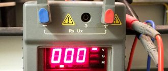
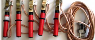
When measuring transient resistances in bolted joints, specialized instruments are used - milliohmmeters. To carry out measuring work, alligator clips are needed. They cover the bolted connection on both sides. As a result, a bus is created between the connecting bolts, the resistance of which is infinitesimal when compared with the resistance at the place where they touch.
It should be noted that in RD 34.21.122 - 87 the maximum contact resistance is indicated as 0.05 Ohm.
Bottom line
Measures to measure and test the performance of lightning protection only seem simple. When actually implementing them, even specialists are faced with a number of intractable issues that are quite difficult to deal with on their own. A striking example of this is the standardization of maximum resistance values of grounding systems.
However, confidence in the performance and reliability of the lightning protection system will be strengthened not only by timely measurement tests, but also by competent interpretation (decoding) of the results by specialized specialists who know all the basics of the regulatory framework and understand the principles of operation of this system.
How to draw up a grounding inspection report
As you might guess, the safety of workers depends on the serviceability of the grounding conductors.
If the device malfunctions, there is a risk of electric shock. When working properly, the ground electrode will conduct current through itself for a certain time. This will prevent a dangerous situation. Accordingly, it is extremely important that grounding devices are in good working order. That is why their inspection is carried out by specialized companies that provide qualified specialists. Naturally, such companies have a license that allows them to carry out such activities. The frequency of such inspections is once every six years. But this applies to thorough checks using special devices. As for visual inspection, visible parts of the grounding should be visually inspected every six months. However, you need to understand that if there is a suspicion of a malfunction, a thorough check can be carried out earlier.
Separately, grounding is checked only in isolated cases, for example, when a malfunction is detected. It is usually checked in conjunction with electrical equipment testing. As you might guess, the purpose of such a test is to determine the quality of the grounding.
It cannot be said that the EL-8 form is strictly mandatory to fill out. However, practice shows that some inspection authorities do not recognize a document as valid if it is drawn up in free form. Thus, experts recommend using this form.
( Video : “Grounding 2 meters? Checking. Grounding circuit 2 and 3 meters, measured.”)
When filling out, you must ensure that there are no errors. Even a minor typo can cause significant distortion of information. If one was discovered after filling out, it is better to start drawing up a new document. This way you can avoid unnecessary questions from inspection authorities.
Contents of the act
At the top of the act, information about the organization on whose balance sheet the equipment subject to inspection is located is indicated. In essence, this party performs the function of a customer. Information about the performing company is also written here. The number of the registration certificate and information about the license are indicated. Below is the title of the document, which reflects the essence of its preparation. Then you can start filling out the main part:
- climatic conditions under which the test took place;
- the purpose of this event;
- it is necessary to mention the documents that the verification results must correspond to;
- type of electrical equipment whose grounding is checked.
Since the grounding system involves the use of soil, its characteristics need to be described in detail. For example, the resistivity of the soil, its nature and type are indicated. Below is a table that is intended to display the results of the research.
The following columns are present here:
- serial number;
- purpose of the grounding device;
- the grounding point at which the test was carried out;
- distance to potential and current electrodes;
- grounding resistance;
- seasonal coefficient;
- conclusion.
In the column intended for conclusion, the responsible persons indicate whether the resistance meets the existing standards or not. Next is another table in which you need to indicate which instruments and special devices were used in research work.
The following information is provided here:
- serial number;
- type of device;
- factory number;
- characteristics of the device;
- dates of inspections of these devices;
- device verification certificate number;
- name of the organization that issued this certificate.
At the bottom of the document there is a “Conclusion” item. If the resistance of the grounding electrode meets the standards, this should be written about. If inconsistencies are found, this should also be reflected in the document. Also in the final part, the specialists who performed the inspection are indicated. Their positions are noted and autographs with transcripts are given. Information about the manager who checked this act is also indicated. Here he also signs and deciphers it. With his autograph, the manager confirms that the correctness of the document has been verified.
It is logical to assume that this protocol specifically concerns the grounding devices being tested. No corrections can be made during compilation. If mistakes are made, experts recommend starting to fill out a new document.