Grounding metal lighting poles
Grounding not only protects people from severe electrical injuries, but also ensures the safety of poles and electrical equipment during severe thunderstorms.
To illuminate streets, squares, parks and other urban infrastructure, a variety of lighting devices are used, usually placed on high supporting structures. An important safety condition when using metal supports is their mandatory grounding.
Advantages of metal supports
Metal structures have a longer service life than their predecessors - wooden and reinforced concrete pillars. They can serve up to 50 years, maintaining the original technical data and excellent functionality.
The advantages of steel supports include the following qualities: special strength;
- resistance to vibration, wind and mechanical influences;
- resistance to significant temperature changes, ultraviolet radiation, high humidity and other adverse natural factors;
- the presence of an additional anti-corrosion layer applied by hot-dip galvanizing;
- compactness, relatively light weight;
- wide variability of constructive and design solutions;
- ease of installation and further maintenance.
Products
Non-force faceted flange support
Faceted conical supports
Tubular flange power support
If you have questions that require immediate resolution, call or write to us!
Grounding of metal supports
Wires of overhead power lines are attached to poles using porcelain or glass insulators, which are characterized by low current conductivity. Violation of insulation carries the risk of electric shock to both a person who happens to be nearby and a specialist working on the power line. To prevent this, steel structures are equipped with a grounding system. Requirements for the organization of grounding are set out in the “Rules for the Construction of Electrical Installations” (PUE) and other regulatory documents.
Grounding methods
Currently, there are two main grounding systems:
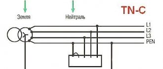
- A system in which the neutral of the power supply is solidly grounded; the support is connected to the neutral wire using a non-insulated jumper, and the contact of the support with the grounding conductor occurs through neutral protective and working conductors (PEN buses).
- A system in which the neutral of the power supply is isolated from ground; The grounding conductor is the metal fittings or cable sheath.
Thanks to the grounding system, the electrical voltage around the metal supports is reduced to a level that is safe for humans. According to the “Rules for the Technical Operation of Electrical Installations” (PTEEP), the resistance level of the ground electrode should not exceed 50 Ohms. Preventive measurements of the grounding device using a special device should be carried out regularly - at least once every six years.
Steel supports and masts
Park decorative supports
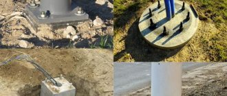
Foundation embedded parts
Re-grounding on a wooden support
For re-grounding, a grounding descent is mounted on a wooden support. The grounding descent is made from a metal rod along a support, which is welded to a pin electrode driven into the ground. It is better to take a rod from galvanized steel if it is thicker than 6 mm or from black steel with an anti-corrosion layer if it is thinner than 6 mm.
For the work you will need the rod itself, a sledgehammer for hammering it in, a set of wrenches (or welding), and a battery-powered cutting angle grinder. You need to choose a battery-powered grinder based on the diameter of the cutting wheel and the presence of two charging batteries. You don’t need an electrical connection to operate, which is very convenient in this context.
Similarly, re-grounding of a reinforced concrete pillar without rebar is done.
On a wooden support where the PEN conductor is re-grounded, all metal hooks and pins of the support must be grounded. If there is no re-grounding of the PEN conductor on a wooden or reinforced concrete support, then the hooks and pins do not need to be grounded (2-4-41 PUE).
All metal electrical equipment located on poles (lightning protection, VU shields, surge protection, etc.) must be grounded with separate wires. The re-grounding resistance should not exceed 30 Ohms (in the case of a solidly grounded transformer neutral).
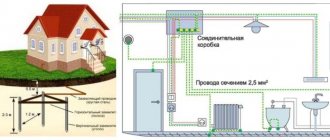
Re-grounding the PEN conductor of the VLI does not cancel the grounding device for a private house with the installation of a ground loop near or around the house.
Practice tips
In conclusion, I will give an order from technical supervision. Where is it necessary to re-ground the VLI section from the transformer substation to the house, 800 meters long.
Related articles: SPDs, surge protection devices
In this option, re-grounding must be done:
- On the last (at the house) and first (at the substation) poles of the line;
- On VLI anchor supports;
- On supports with a step of 100± meters from the first support, with grounding.
©Ehto.ru
Useful to read
- No entries found
What is it for?
Outdoor lighting system supports
Grounding for a network of outdoor lighting poles or overhead lines (0.4, 6-10, 20 and 35 kV) is of great importance, since it prevents the risk of electrical injury when coming into contact with structural elements in a situation where cable insulation is damaged. If there is grounding on a metal support of an outdoor lighting network or overhead line, the voltage “spreads” along the ground, thereby becoming safe for people. This indicator depends on the resistance of the soil in which the overhead line support is installed (0.4, 6-10, 20 and 35 kV). As a result, even if a violation of the overhead line insulation occurs somewhere, the structures will remain safe.
Under normal operating conditions, pin insulators mounted on supports will provide reliable insulation of all wires from structural elements. But there are situations when the voltage in the network significantly exceeds the voltage for which the overhead line was designed (0.4, 6-10, 20 and 35 kV). In such an overvoltage situation, a breakdown of the overhead line insulation is possible and, as a result, the network fails. In order to limit the value of overvoltage and improve safety, it is necessary to reduce the resistance for "current spreading". For this purpose, protective grounding is installed on overhead lines (0.4, 6-10, 20 and 35 kV) and supports for external lighting.
Grounding methods
For each type of electrical supports, the PUE has developed conditions and methods of grounding. There are 3 types of power line poles:
- wooden;
- reinforced concrete;
- metal.
Clause 6.1.45 of the PUE states that reinforced concrete and metal supports in networks with an insulated neutral must be connected to a grounding conductor, in networks with a grounded neutral - to a PE (PEN) conductor.
Reinforcement on wooden poles is not grounded.
Important! Wooden poles are grounded only if they are installed in a populated area with one-story buildings and their height exceeds the height of the buildings.
Grounding of reinforced concrete supports is carried out in two ways:
- In networks with an isolated neutral and in the presence of special outlets, longitudinal reinforcement of the structure is used as grounding lines (conductors). In its absence, the conductor is a rod with a diameter of at least 10 mm or a stranded wire with a cross-section of at least 35 square meters. mm. One end of the conductor is connected to the grounding electrode, the other to the grounded elements.
- In networks with a grounded neutral, the fittings and support are connected to the neutral wire using a jumper made of bare conductor. When connecting, branch bolt clamps are used. To connect the conductor to the support, use a bolt clamp or eyelet on a pole or crossarm.
Metal supports are installed more often; they have the following advantages over wooden and reinforced concrete ones:
- able to withstand large static loads;
- functional in any climate zones;
- wide choice of shapes and designs;
- long service life, up to 75 years.
Grounding of metal supports is carried out in the same way as reinforced concrete masts. The support body can serve as a grounding conductor. The grounded elements are connected to the support, and the base of the support is connected to the ground electrode.
PUE requirements
The PUE is regulatory documentation that should be relied upon when implementing protective grounding measures (repeated or not) of power transmission network supports or outdoor lighting. The ground loop should always be installed according to these rules to avoid problems in the future. The PUE contains the following recommendations:
- if there is an electrical installation with a solidly grounded neutral, first of all the neutral wires of the beginning of the overhead line should be grounded;
Grounding on each support
Grounding on each support
Note! In this situation, the ground loop does not need to be installed at the first support. This is due to the fact that here the neutral wire will be tightly connected to the neutral point of the power source.
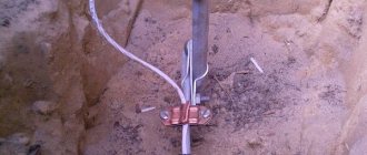
Protective grounding: 1 – places for welding; 2 – the ground electrode itself; 3 – conductor to the ground electrode.
- in the presence of electrical installations with a solidly grounded neutral, re-grounding as overvoltage protection should not be installed very often (step is a kilometer of line);
- any subsequent re-grounding must have a resistance of up to 10 ohms (maximum). If there is an installation with a power of more than 100 kVA. If the installation power is lower, then the resistance should be up to 30 Ohms (maximum);
- For overhead line supports, grounding devices must be installed if repeated overvoltage protection is necessary. It is allowed to use structures for protection against overvoltages of natural origin (lightning). In this situation, the resistance for the grounding device should be taken no higher than 30 Ohms;
- any metal structures must be connected to special PEN conductors;
- if there are reinforced concrete supports, special PEN conductors must be connected to the reinforcement of the struts and support posts;
- When installing self-supporting insulated wires that have insulated supporting conductors, supports (reinforced concrete and metal wooden, for overhead lines) are not subject to surge protection. Here re-grounding is needed for pins and hooks. This is done in order to form protection against overvoltages of atmospheric origin.
By following these recommendations, the installation of surge protection, regardless of whether it is repeated or not, will be carried out efficiently. It will also be possible to select the correct resistance for each support option.
Features of grounding measures
To avoid operational problems and accidents, the grounding installation sequence should be as follows:
- According to the grounding diagram, which indicates the method of arrangement and the number of electrodes, a trench of the required dimensions is dug. Depth measurements should be taken from the beginning of the support.
- The charger is being immersed.
- A grounding loop for the lighting support is formed by welding individual parts of the charger together.
- Anti-corrosion treatment of welding seams is carried out.
- The ready-to-use protective device is connected to the support.
- Control measurements of the device operation are carried out.
Do I need to ground lighting poles and how to do it correctly?
External lighting systems are designed to illuminate roadways in populated areas and at highway interchanges, sidewalks and indoor areas, necessary areas at protected sites, and personal plots in private households at night. For their safe operation, grounding of lighting supports (masts, poles) and external lamps is used.
Installation of external lighting systems is carried out in accordance with the requirements of the Electrical Installation Rules (PUE).
Grounding metal lighting poles
According to the standards, it is carried out with the mandatory connection of metal supports, as well as reinforced concrete components and cables to:
- PEN type conductor (if it is an electrical network with a grounded neutral);
- grounding conductor (if the network provides for an insulated neutral).
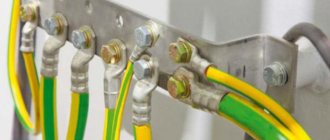
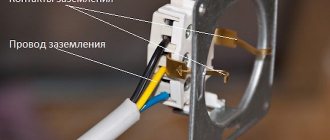
In the latter case, protective devices are implemented for hooks of phase wires, as well as pins, fittings and other metal elements. To do this, use a grounding loop and appropriate conductors.
Attention! The foundation is not a grounding device due to the presence of a special mastic coating. It has high anti-corrosion properties, as well as dielectric characteristics.
Electrical safety standards
Grounding of lighting poles is regulated by PUE, GOST and SNiP standards. Key provisions from these documents:
— the grounding method is chosen based on the parameters of the lighting networks and the type of soil. Moisture saturation and soil category matter; — the diameter of the grounding conductors to which the grounding conductors are connected is calculated based on soil parameters. Minimum diameter – 6 mm; — grounding conductors, both in the form of rods and plates, are driven vertically into the ground to a depth of 3 m; — if soils are characterized by increased resistivity, counterweights are used for grounding. These are horizontal electrodes that are located continuously and connect several lighting supports at once; — cross-section of the grounding line – from 100 mm2. When using lightning protection – from 160 mm2; — for dry soils, grounding devices with a diameter 2-3 mm higher than the minimum value are used, for wet soils – up to 2 times larger; — distance from the top of the elements to the base of the soil – 0.5 m; — for wet soils, grounding conductors with a large cross-section are used;
Useful tips
If it is necessary to re-ground the overhead line from the transformer substation to the residential premises at a distance of 800 m, it should be done in the following places:
- on overhead line poles, which are located near the transformer substation and near the house;
- on overhead power line anchor posts;
- on a support with a distance of 100 meters from the main grounded support.
We also recommend watching a video that shows how to re-ground, or rather, drive the pins into the ground without any problems:
Useful on the topic:
Reinforced concrete supports
Reinforced concrete supports are rectangular or trapezoidal structures made of reinforcement and concrete. Reinforced concrete supports are marked as SV. Next comes the marking number, which indicates the length of the support. For example, the SV 95 support has a length of 9.5 meters.
The following reinforced concrete supports are used:
- SV 85;
- SV 95
- SV 110;
- SV 105.
On the CB supports, fittings are welded at the top and bottom to re-ground the PEN conductor.
But let's get back to re-grounding.
Re-grounding is called re-grounding because this wire is already grounded at the transformer substation.
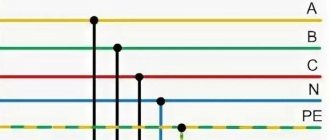
A transformer with a solidly grounded neutral (TN-CS) assumes that two or four SIP wires run along the VLI. One or three phase wires, plus a PEN conductor (it’s a load-bearing one). The PEN conductor is divided into a neutral working wire (N) and a neutral protective wire (PE) conductor on a pole if you install an IU (input device) on it or in a switchboard in the house.
Let me remind you that the PEN conductor is divided into a neutral working wire (N) and a neutral protective wire (PE) conductor on a pole if you install an IU (input device) on it or in a switchboard in the house.
According to the PUE, re-grounding of VLI is grounding of the PEN or PE conductor of VLI of power transmission lines.
How to re-ground VLI.
Related articles: The meter burned out - what to do