In the modern world, people are surrounded by a huge number of electrical and electronic devices. Along with the undeniable advantages of such useful inventions of the human mind, we get one big minus - expensive repairs. A personal computer, a laptop, a DVD player, and a satellite receiver are complex electronic devices, the cost of repairs of which can reach several thousand rubles. Sometimes these amounts that we pay for repairs to an electronics technician are unreasonably high. But fortunately, we have the power to learn basic diagnostic techniques, as well as simple repairs that can be done at home. This article will discuss typical breakdowns of the most common electronics, as well as ways to quickly troubleshoot problems with minimal expenditure of money and nerves.
Is it possible for a beginner to learn how to repair electronics?
To repair electronics yourself, you don’t have to be an ace in this matter, but certain knowledge of a school physics course is still necessary. It’s good if you attended a radio engineering club at school. If you want to repair electronics, then such concepts as electrical resistance, current, emf, inductance, capacitance should not be unclear to you. Some experience in soldering radio components is required, as well as minimal skills in using an electrical tester or multimeter.
DIAGNOSTICS AND REPAIR OF ELECTRONICS WITHOUT SCHEMATICS
In the life of every home craftsman who knows how to hold a soldering iron and use a multimeter, there comes a time when some complex electronic equipment breaks down and he is faced with a choice: send it to a service center for repairs or try to repair it himself. In this article we will look at techniques that can help him with this.
So, your equipment is broken, for example an LCD TV, where should you start repairing it? All craftsmen know that it is necessary to begin repairs not with measurements, or even immediately resolder the part that aroused suspicion of something, but with an external inspection. This includes not only inspecting the appearance of the TV circuit boards, removing its cover, looking for burnt radio components, and listening to hear a high-frequency squeak or click.
We connect the device to the network
To begin with, you just need to turn on the TV to the network and see: how it behaves after turning it on, whether it responds to the power button, or the standby mode LED is blinking, or the image appears for a few seconds and disappears, or there is an image but there is no sound, or vice versa. Based on all these signs, you can obtain information from which you can build upon for further repairs. For example, by blinking an LED at a certain frequency, you can set a fault code, self-testing of the TV.
TV error codes by LED blinking
After the signs have been established, you should look for a schematic diagram of the device, or better yet, if a Service manual for the device has been issued, documentation with a diagram and a list of parts, on special websites dedicated to electronics repair. It will also not be amiss in the future to enter the full name of the model into a search engine, with a brief description of the breakdown, conveying its meaning in a few words.
True, sometimes it is better to search for a diagram by the device chassis, or the name of the board, for example a TV power supply. But what if you still couldn’t find the circuit, and you are not familiar with the circuitry of this device?
Block diagram of LCD TV
In this case, you can try to ask for help on specialized forums for repairing equipment, after conducting preliminary diagnostics yourself, in order to collect information from which the technicians helping you can build on. What stages does this preliminary diagnosis include? First, you must make sure that power is supplied to the board if the device does not show any signs of life at all. This may seem trivial, but it wouldn’t hurt to test the power cord for integrity using the audio test mode. Read here how to use a regular multimeter.
Tester in audio mode
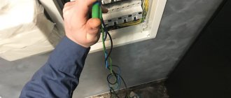
Then the fuse is tested in the same multimeter mode. If everything is fine here, we should measure the voltage at the power connectors going to the TV control board. Typically, the supply voltages present on the connector pins are labeled next to the connector on the board.
TV control board power connector
So, we measured and there is no voltage at the connector - this indicates that the circuit is not functioning correctly, and we need to look for the reason for this. The most common cause of breakdowns found in LCD TVs are banal electrolytic capacitors, with high ESR, equivalent series resistance. Read more about ESR here.
Capacitor ESR Table
At the beginning of the article, I wrote about a squeak that you may hear, and so its manifestation, in particular, is a consequence of the overestimated ESR of small-value capacitors located in the standby voltage circuits. To identify such capacitors, you need a special device, an ESR meter, or a transistor tester, although in the latter case, the capacitors will have to be unsoldered for measurement. I posted a photo of my ESR meter that allows me to measure this parameter without soldering below.
My ESR meter
What to do if such devices are not available, and suspicion falls on these capacitors? Then you will need to consult on repair forums and clarify in which node, which part of the board, the capacitors should be replaced with ones that are known to work, and only new (!) capacitors from a radio store can be considered as such, because used ones have this parameter, ESR may also be off the charts or already on the verge.
What kind of damage can you fix yourself?
Some beginners mistakenly believe that a personal computer can only be repaired in a service center. Practice shows that most breakdowns can be fixed at home using simple equipment. But it’s worth making a reservation that you most likely will not be able to replace any microcircuit on the computer’s motherboard. Although you can replace electrolytic capacitors on the same motherboard at home, armed with some simple soldering iron. Therefore, you should immediately understand which breakdowns you can fix yourself, and which ones – only in the service.
How to fix an electronic device that won't turn on
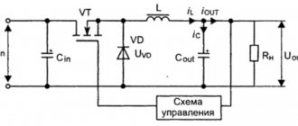
If you plug the device into a 220V power supply, but there is no reaction: there is no light or sound indication of operation, then most likely the power supply has stopped working. We recommend connecting any device that does not respond adequately when plugged into the network in series with a powerful incandescent lamp so as not to cause a short circuit. If the switching power supply of the device is working, then the incandescent lamp will not light up, but if there is a short circuit on the input of the unit, then the incandescent lamp will perform a protective function and will burn at full intensity.
How to check a switching power supply
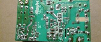
In fact, the switching power supply has an almost standard design in many electrical devices. First, we check it for the most commonplace possible breakdowns - a broken network cable and blown fuses. You can significantly speed up diagnostics if you measure the voltage across the largest capacitor in the switching power supply. As a rule, it is installed after the diode assembly and after the surge protector. If there is approximately 300V DC voltage, then you will automatically know that the fuse, the power filter, the power cable, and the input chokes are fully operational. There are blocks where instead of one huge 400V capacitor there are two. In such blocks, the voltage on each capacitor is approximately 150V. If there is no voltage, then it is best to check everything separately: ring the network cable, check each rectifier diode, fuse, capacitors, chokes, etc. Moreover, fuses can be very insidious: outwardly they look quite serviceable, but when tested they have an infinitely high resistance. This is due to the fact that in fuses, a break or burnout can occur in a place that is not at all visible.
Electrolytic capacitors are the weakest point of modern switching power supplies. A decrease in capacity and an increase in the ESR value leads either to a complete failure of the power supply unit or to a violation of the output voltage parameters. All swollen capacitors must be replaced. Also, take the time to check the ESR parameter, as well as the capacitance value of all suspicious capacitors. The compact device ESR-micro v4.0s copes best with this task. Fortunately, capacitors are not expensive, so you can simply replace any suspect capacitors with known good ones. The reliability and quality of repairs will only benefit from this. The main thing to remember is that electrolytic capacitors have polarity, therefore, they must be soldered strictly according to the loop. After replacing the capacitors, most units begin to operate normally, unless, of course, there are problems with PWM chips, diodes, output stabilization circuits, etc.
How to learn how to properly and quickly repair television and radio equipment in 1 day?
Good afternoon. This article briefly but essentially discusses a very important topic for novice repairmen - knowledge of the correct DIAGNOSIS, REPAIR and POST-REPAIR CHECKS of radio equipment. Taking into account the fact that it is not possible to fully describe the repair process, for obvious reasons. After reading this article, you will greatly improve your knowledge and skills in troubleshooting.
FOR REPAIRS, IT'S ENOUGH TO KNOW A FEW USEFUL RULES.
1. ACCEPTANCE, SURVEY. Before accepting a device for repair, it is very important to feel free to ask the owner about how the device broke down, what preceded it, whether there were odors, loud pops, lights, etc. This will help you a lot in repairs later. Focusing on its history and malfunction, immediately warn the owner how much it will cost, and what to expect from the device in the future, focusing on the “age” of the device.
2. INITIAL INSPECTION AND CHECKING. Start by carefully inspecting the device, turning it on, listening, identifying burning odors, and inspecting its operation. Next, disconnect it from the network, open it, carefully inspect the inside, inspect the board, connections, inspect for burnouts, odors, bulges, ring cracks, electroplating of the board (shiny stains from a short circuit), swollen capacitors, burnt radio components, moisture, mold, dust, dirt, etc. Eliminate any obvious defects identified. Eliminate any detected faults.
3. INITIAL REPAIRS. If the above measures do not help, take a multimeter in your hands and check the semiconductor parts for a short circuit (breakdown). Resistors do not break through - they either break off or, more rarely, lose their resistance. Electrolytic capacitors rarely break through, more often lose capacity, swell from overheating, and acquire parasitic resistance. Using a universal ESR meter, we check first of all the electrolytes (electrolytic capacitors), then, if necessary and complicated, other suspicious parts. Non-polar capacitors are rarely damaged. Mostly, faults appear in power supplies, in mechanical parts, as a result of their wear (variable resistors, switches, etc.)
4. SERIOUS REPAIRS. Further, if this does not help, if possible, we arm ourselves, first of all, with the basic electrical diagram, and secondly with the structural and wiring diagrams, which will be ideal for a beginner. If not, we find the datasheets for the radio components and use them to guide the repair. Practice shows that this is quite enough, with the proper experience in repairs and ingenuity. In the worst case, we copy the circuit from the board (or remember), at least in general terms. It is important to understand the logic of the device, its electrical circuit, which is important, this will immediately make your repair easy and clear. If this does not help, we check the voltages at the control points, “block by block.” We analyze the results of stress monitoring. If there is an excellent opportunity, we look at the supply voltages on an oscilloscope, their signal shapes, the shapes of other control voltages, signal distortion, etc. We analyze according to the scheme or based on experience, or according to our own logical considerations and knowledge. If there is not enough knowledge, we ask other repairers on our website remonter.info, create an appropriate topic in the “Forum” of our website. We communicate in chats on other resources, watch videos on YouTube, buy Andrei Golubev’s video discs, read theory and relevant literature. Ideally, we enroll in specialized educational institutions, enjoy the acquired knowledge, skills, communication and friendship with acquired colleagues “in the shop.”
5. IMPORTANT! If the malfunction is serious and requires exceeding the monetary costs previously agreed with the owner (estimated, “Repair + parts”), WE NOTIFY THE OWNER and warn. Based on this important point, the outcome of the event is decided. The owner weighs and makes his verdict. We try not to confuse the owner with the search for radio components, since he is already “up to his ears in worries” and it is convenient for him not to be disturbed over trifles. Although there are other cases when the owner does not trust you and prefers to buy the faulty part himself. Also, DO NOT FORGET ABOUT SAFETY when working under voltage!
6. CHECKING, RUNNING. Performance monitoring and post-repair adjustment. Understanding the results of repairs and runs. If a malfunction is found, we eliminate it, taking into account that this place does not again become that “weak link.” To do this, just in case, we check the radio components around the faulty parts, i.e. in the so-called “liability.” If necessary, we take measures to enhance the reliability of the repaired device. Again we check the voltages and oscillograms at the control points. If everything is normal, we set the device to “run”, i.e. We operate it in moderately critical and short-term highly critical conditions, for a certain time. By carefully observing and identifying the identified weak points. If such things appear, it’s good for you, you won’t have to blush later.
7. DEMONSTRATION, CONDITION, RECOVERY. Before handing over the device to the owner, WE MUST DEMONSTRATE to him the proper operation of the device. We focus attention on weak points, repeating ourselves, if any, without hesitating to warn him about it. In order to avoid later troubles, returns due to misunderstanding, disputes - “I didn’t hear”, “I should have said right away”! and misunderstandings.
RESULT. Today you have become familiar with a simplified radio repair algorithm. It is important - do not forget that radio equipment loves to be treated with care and sincerity. Cannot stand negligence, rudeness and aggression towards oneself. As experienced craftsmen say: “Device has a soul.” They sense our mood.” If you want to be remembered with a kind word, your fame will spread throughout the area, and your clients will increase, then do it efficiently, putting your soul into it. Not forgetting about competitors (intrigues, gossip, sympathy for them, understanding them, better friendship with them) and about adequate payment for repairs.
Good luck with your repairs!
2
Author of the publication
offline for 2 days
Vasya
252
Thoughts tend to materialize!
Comments: 89Publications: 28Registration: 03/25/2018
How to find a short circuit if the power supply goes into protection mode
It happens that a switching power supply starts to work normally only when disconnected from the main board. For example, the computer power supply turns on only when it is disconnected from the motherboard and “started up” using a jumper that connects the green and black wires. To find a place or radio element that provokes a short circuit, you need to spend a lot of time. To simplify this task as much as possible, we recommend applying a current-limiting constant voltage from a laboratory power supply to the problem line in the motherboard. Using touch, as well as using fax paper, we find the area where there is the highest heating. Therefore, this is where the faulty element is located. Finding and fixing the problem takes no more than 15 minutes.
Troubleshooting a laboratory power supply
Analysis of the situation
We begin troubleshooting by analyzing the situation.
So, we have a laboratory power supply being repaired. Well, I analyzed the situation. Power overload, as a result of which it began to produce 24 Volts, instead of the required 0-15 Volts. The voltage is not adjustable. This means that some radio element died. In order to determine the cause of the malfunction, we must find a circuit diagram for it and open our power supply. As they say, “an autopsy will show.”
Opening our power supply
Finding the cause of the malfunction
At this stage, we must determine the cause of the breakdown, and also simultaneously analyze the situation. As usual, we begin our inspection with the power source. Our transformer is normal, as in the diagram, it gives us an alternating voltage of 20 Volts. After the diode bridge, the voltage on the capacitor is 35 Volts. We go this way, checking all the elements along the way. In order to learn how to check radio elements, you need to read the articles:
How to measure:
- current with multimeter
- how to check and measure voltage
- resistance with multimeter
How to check:
- bipolar transistor multimeter
- diode with multimeter
- capacitor with multimeter
- fuse with multimeter
It’s better to read all the articles on the site)
Your senses are your helpers
In order to determine a malfunction, our five senses often help, but we will use four:
- Vision (eyes)
- Touch (skin)
- Olfaction (smell)
- Hearing (ears)
Use them as often as possible. A visual inspection can give you 80% of finding the fault. This could be a burnt element, or a printed circuit, as well as a break or, conversely, a short circuit. Don’t be lazy, carefully examine the broken thing from all sides.
The sense of touch can also greatly help you in troubleshooting. If you plug the device into the network and touch large resistors (their dissipation power is usually large), then they should be warm or even a little hot. If they are cold, it means either there is a break in the resistors, or the voltage does not reach them. The microcircuits should be cold or a little warm. Processors or powerful chips are hot. If they are too hot, then it’s the Khan’s chip or processor. Capacitors and inductors should be cold.
All this comes with experience. Use touch as much as possible, but be very careful. If you touch the terminals of the elements, you may get a good electric shock, depending, of course, on which circuit contains what current.
A real electronics engineer should know the smell of burnt silicon, wires, the smell of a burnt transformer, a burnt board, etc. by heart. Strain your sense of smell and try to catch the “aroma” of a malfunction. If the equipment burns out in your presence, then immediately sniff and visually inspect it.
Listen to the operation of faulty equipment. You may hear some crackling, squeaking, buzzing or something else. For example, the hum of an asynchronous motor indicates that one of the phases may be broken or the bearings are not spinning. If the transformer hums, this may mean a short circuit in the windings.
Determining the defective node
Having opened the power supply, I discovered that my microcircuit gets very hot when I turn on the power supply and press the POWER button on the unit itself. Most likely there is a short circuit in it. We find a datasheet for this microcircuit on the Internet. In my case it is LM723. It is a voltage regulator.
But trouble does not come alone. The transistor also burned out - BD140.
We make a decision
I went to the store to get new spare parts. Total, the microcircuit is 20 rubles, the transistor is 10 rubles. Together 30 rubles.
Well, we need to unsolder the microcircuit, for this we use our desoldering pump. The photo shows a view of the board from below the microcircuit.
We get
We pull out the microcircuit using a simple extractor tool
We prepare a new microcircuit and tin its terminals with LTI-120 flux
We insert it into our holes where the microcircuit was located. Insert exactly the same way the dead chip was! For those who don’t remember how it stood, hardware manufacturers often draw its image on the board. It turns out that the chip recess should be on the right.
We insert it as needed
Lubricate the areas with gel flux
And we solder each contact pad in turn with a drop of solder on the tip of the soldering iron.
We carry out all the same operations with the transistor.
My power supply worked as it should. You can, of course, modify it, but this requires time and relevant knowledge. But for now I'm quite happy with it.
How to fix a device that turns on but does not work correctly
The most difficult problem is a fault that appears and disappears. The sudden nature of the occurrence and inexplicability of the disappearance of a malfunction of electronic equipment can baffle even an experienced technician. If you notice that your computer suddenly turns off after several hours of playing, but after waiting 20-30 minutes, it is ready to work again, then you should look for a malfunction in the thermal regime, as well as in broken contacts. First of all, check which microcircuits or radio components are particularly hot. If you do not have a special temperature probe, you can simply measure the temperature by touch. Insufficient cooling, dried thermal paste, dust - these are the main causes of overheating, leading to unstable operation.