What is alternating current
In DC circuits, negatively charged particles move from plus to minus. If we consider a current source as a kind of two-terminal network that has two electrodes to which the powered circuit is connected, then one will always have a plus, and the other will always have a minus.
Alternating current does not allow such pole markings to be recorded. With a two-terminal AC circuit, it is impossible to clearly indicate what charge is present at which terminal. You can only consider instantaneous values of charges in a certain period of time. The polarity change has a time dependence. This means that alternating current changes direction over time.
Important! Alternating electricity changes according to a harmonic sinusoidal law. Its graph on the coordinate axis is a sinusoid, while the graph of the constant motion of electrons is a straight line parallel to the OX axis
Graphic representation of two types of electricity
Direction of direct current and symbols on electrical devices and diagrams
To simplify calculations and create electrical circuits, the direction of this parameter is taken towards a point with a lower potential (from plus to minus). In reality, particles only move this way when they have a positive charge. In a metal, the direction of electron flow is reversed, but to avoid confusion, the indicated basic principle is used.
The insulation of positive terminals (probes, cables) is indicated in red, negative - black or blue. If the accompanying text indicates dc voltage, this means that the current in the corresponding circuit will be constant. On drawings and product bodies, symbols are used in the form of parallel lines (solid and broken).
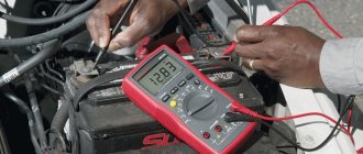
To measure DC current, the multimeter switch must be moved to the appropriate position
For your information. Anode (cathode) is the terminals of a vacuum tube or other part that are connected to the positive (negative) electrode of the battery.
You can also find the designation ac; what it is is described in detail in the final section of the article. The direct decoding of the abbreviation “alternating current” is not always correct. However, in a narrow sense, they mean a sinusoid with variable polarity, which is denoted by the Latin letters “AC”, a characteristic single wavy symbol, or a standard mathematical sign of approximate equality “≈”.
What is the difference between DC current and AC current?
Initially, direct current was supposed to be generated in power plants with a relatively low outlet voltage for the consumer, 110 or 220 V. However, if several consumers are connected with this option, the total values are very high. In this case, thick and expensive cables are required to cover long distances to keep transmission losses within certain limits. When using alternating voltage, the generated electricity can be transported over relatively long distances with little loss. Since 1980, it has been possible to rectify three-phase high voltage current and then convert it back.
The main difference between AC and DC, direct and alternating currents is that the first changes at certain intervals (with a certain frequency), in particular, it changes direction as it flows. The most common frequency in the world is 50 Hz.
Note! When electricity reaches the consumer, then transformers are used. They convert high voltage into lower voltage, which is supplied to homes
Voltage transformer
As already stated, DC electricity does not change over time. And since electrons only move in one direction, sources are characterized by the presence of positive and negative poles. AC is more efficient when using many kilometers of power lines. And direct current is preferable for small electronics or storage elements, such as solar panels.
What does AC and DC mean on the multimeter panel
On the operating panel of any device, DC is a designation for direct voltage. By setting the switch to such constant current icons, constant electrical quantities can be tested.
The AC symbol is intended to indicate the limits within which the tester can operate with varying amounts of electricity.
Important! If the numerical order of the measured quantity is not known, then it is necessary to set the maximum measurement limit, gradually reducing it until the required testing accuracy is achieved. If the type of current is also unclear, it is better to assume that it varies with time.
The designation of alternating current on circuits and devices necessarily indicates its voltage, frequency and number of phases. Notation standards provide for an unambiguous and understandable symbolic display of information for specialists.
Sources of electrical energy
The most common sources are galvanic cells, batteries, and special electrical generators that are based on unipolar induction.
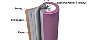
AA battery
Regular AA batteries are the most affordable example of a DC energy source. It has positive and negative poles, and it must be inserted into various electrical devices with a certain side. In addition, solar cells and car batteries are very often used in everyday life.
Note! An electric generator, which is used when higher power is required, always generates alternating voltage. To be able to receive direct current from it, a commutator was previously used
Because switches cause radio interference and their contacts wear out, they are now more often replaced with rectifiers.
The generator must come with a switch
What is the difference between AC and DC current
Current is the movement of charged electrons in a certain direction. This movement is necessary so that household and professional electrical appliances can operate at the installed rated power. In a home outlet, current comes from a power plant, where the kinetic energy of electrons is converted into electrical energy.
Constant current is electricity obtained from a phone battery or battery. It is called so because the direction of movement of electrons in it does not change. The operation of chargers is based on this principle: they convert alternating electricity from the network into direct electricity and in this form it accumulates in batteries.
Alternating current is electricity in any home electrical system. It is called so because the direction of electron movement is constantly changing. The number of direction changes is determined by the frequency, which for home networks in the CIS is 50 Hz. This means that in one second the electric current changes direction as many as 50 times. The voltage in the network is the maximum “pressure” that causes electrons to move.
Sign and color marking of AP elements
In accordance with the requirements of GOST R 50462, conductors and buses of electrical networks with a grounded neutral must be marked “PE” with the addition of a dashed line of alternating yellow and green stripes at the end sections of the route. At the same time, the tires of the working “zero” are indicated in blue and marked as “N”.
In those circuits where neutral working conductors are used as a protective grounding element with a connection to a grounding device, blue color is used when designating them.
At the same time, they are labeled “PEN” and alternating yellow and green strokes are added to the end sections of the schematic symbols.
It should be noted that strict compliance with all provisions and requirements of GOST and PUE will allow the consumer to organize the safe operation of the equipment at his disposal.
Transformer device
In accordance with GOST 16110 −82, the definition of a transformer is as follows: a transformer is an electromagnetic device of a static type, which is equipped with two or more inductively coupled windings and is designed to convert one or more alternating current systems into one or more other systems.
This electromagnetic product has a simple design consisting of the following elements: magnetic core (magnetic system), windings, winding frames, insulation (not in all transformers), cooling system. additional elements. In practice, manufacturers use one of three basic concepts to produce transformers:
- Rod. The windings are wound on the outermost rods.
- Armored. The side walls remain without windings.
- Toroidal. It has a ring shape with uniform winding around the entire circumference.
Magnetic system
Magnetic cores for a transformer have a certain geometric shape and are made from a number of materials, which include electrical steel, permalloy, ferrite or other material with ferromagnetic properties. Depending on the material and design, the magnetic circuit can be assembled from plates, pressed, wound from a thin tape, or assembled from two, four or more “horseshoes”.
We advise you to study the Electrical Safety Group
The rods act as a frame for placing the main windings. They can have different spatial arrangements, depending on which several types of systems are distinguished.
- A flat magnetic system with the longitudinal axes of rods and yokes located in the same plane.
- A spatial system where the longitudinal axes of the rods are located in different planes.
- A symmetrical system equipped with identical rods that have the same relative position in relation to the yokes.
- An asymmetrical system consisting of rods, some of which may differ in shape, design and size, with different relative positions in relation to the yokes.
Winding design
The winding is the main element of the transformer. It is a multi-turn structure made of one or more copper (less often aluminum) wires of various diameters. As a rule, power transformers use conductors with a square cross-section, which allows more efficient use of available space, thereby increasing the fill factor (K).
To prevent short circuits, each winding is insulated. Special paper or enamel varnish can be used as an insulating material. By the way, if two separately insulated and parallel-connected wires were used to make the winding, then they can be equipped with a common paper insulation.
Fuel tank
The tank is one of the most important additional elements of the transformer. It is a container designed to store transformer oil, as well as provide physical protection to the active component. In addition, the tank body is designed for mounting auxiliary equipment and a control device.
One of the internal elements of the tank is a high-current resonator. It is subject to rapid and frequent overheating when the rated power and transformer currents increase. To reduce the risk of overheating, inserts made of non-magnetic materials are installed around the resonators.
The internal coating of the tank is made of conductive shields that do not allow magnetic fluxes to pass through the walls of the tank. Sometimes there is a coating that is made of a material with low magnetic resistance. This coating option absorbs internal flows before approaching the walls of the tank.
AC symbol
have a more simplified electronics circuit - there is no inverter in the circuit (in some cases there is only a “fake” one). Most often, the “life” of such blocks is very short, so the warranty period is quite short. When using blocks with a type of lamp that does not correspond to them, it leads to a significant reduction in the “life” of the blocks. The discrepancy between the blocks and lamps can be detected visually - when using DC blocks with AC lamps, the effect of “shaking of light” appears, which occurs due to the instability of the electric arc in the bulb. If you use AC units with DC lamps, then such a combination will not work at all, because The DC lamp has polarity, and the AC unit produces alternating current (without polarity). Another difference is the sound... AC ballast emits a fairly loud characteristic “squeak” at the beginning of ignition, which subsides as the lamp ignites, while DC ballast does not make a single sound, or emits a very quiet monophonic squeak throughout operation .
AC xenon has a different operating principle than DC. Due to the more complex circuit of AC blocks, a higher luminous efficiency of the lamps is achieved, but the price is also slightly higher. The AC unit itself has either a two-component structure (slim - thin): the main part is in a metal case, and the high-voltage part is placed in a separate plastic case; or one housing in which both parts of the circuit are located. Typically, AC units have a defect rate of 0.5 to 2, while DC units have a defect rate of 5 percent or more.
Observe the correct xenon configuration: DC units + DC lamps, or AC units + AC lamps.
P.S. All ignition units and xenon lamps of the LX (Legal Xenon) brand are AC type!
AC voltage
As we know from physics lessons, current is the movement of charged particles that occurs under the influence of an electromagnetic field, potential difference and tension. The main characteristic of any voltage is its dependence on time. Based on this, a distinction is made between constant and variable quantities. The value of a constant practically does not change over time, but the value of a variable changes.
In turn, a variable characteristic can be periodic or non-periodic. Periodic is a voltage whose values are repeated at regular intervals. The non-periodic is capable of changing at any period of time.
Voltage in an alternating circuit is a parameter that changes its value over time. To simplify explanations, sinusoidal harmonic alternating voltage will be considered in the following.
The minimum time during which a variable repeats is called a period. Absolutely any periodic quantity can be written as a dependence on any function. If time is t, then the dependence will be denoted by F(t). Thus, any period in time has the form: F(t+-T) = F(t), where T is the period.
We advise you to study How to make lighting in a garage and its varieties
The physical quantity that is the reciprocal of the period is called frequency. It is equal to 1/T. Its unit of measurement is the hertz, while the unit of measurement of the period is the second.
f = 1/T, 1 Hz = 1/s = s to the minus first power.
Important! The most common functional dependence of a variable network is in the form of a sinusoid. That is why it was taken as the basis for this material.
It is known from mathematics that a sinusoid is the simplest periodic function, and with its help, any other periodic functions can be represented from several sinusoids with multiple frequencies.
Sinusoidal voltage in absolutely any period of time can be described by the instantaneous characteristic: u = U * sin(ωt + φ), where ω = 2πf = 2π/T, where U is the maximum voltage (amplitude), ω is the angular rate of change, φ is the initial phase, which is determined by the displacement of the function relative to the zero coordinate point.
Part (ωt + φ) is a phase that characterizes the voltage value in a specific period of time. From this it turns out that amplitude, angular velocity and phase are the main characteristics of variable networks that determine their values in any time interval.
Important! When considering a sine function, the phase is often taken to be zero. In practice, they also often resort to some other parameters, including effective and average voltage, shape factor
Decoding the symbols 20k and 20m on a multimeter
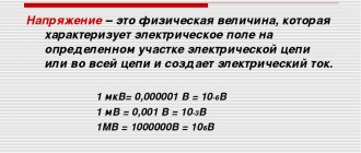
Next to the numbers indicating the measurement range, you can see letters such as µ, m, k, M. These are so-called prefixes, which indicate the multiplicity and fractionality of units of measurement.
- 1µ (micro) – (1*10-6 = 0.000001 from unit);
- 1m (millies) – (1*10-3 = 0.001 from unit);
- 1k (kilo) – (1*103 = 1000 units);
- 1M (mega) – (1*106 = 1,000,000 units);
For example, to check the same heating elements, it is better to take a tester with a megometer function. I had a case where a malfunction of the heating element in a dishwasher was detected only by this function. For radio amateurs, of course, more complex devices are suitable - with the function of measuring frequencies, capacitor capacity, and so on. Nowadays there is a very large selection of these devices; the Chinese don’t do anything.
{SOURCE}
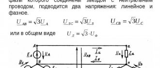
Three phase system
The most widespread in electrical engineering is the symmetrical three-phase electrical system. d.s. It represents three variables e, identical in frequency and amplitude. d.s., between which there is a shift of 1/3 of the period. The totality of currents arising under the influence of these e. d.s., is called a three-phase current system or, as they usually say, three-phase current.
If the loads of all three phases are identical in all respects (for example, they represent the windings of a three-phase electric motor, or a theater chandelier in which each of the phases powers the same number of identical lamps, or is a three-phase capacitor bank and the like), then the three-phase current system will be symmetrical. This is the most favorable and simplest case.
In a symmetrical system, the current values of all phases are equal, the currents are equally shifted relative to the corresponding voltages, and between the currents of adjacent phases the shift is equal to 1/3 of the period.
In practice, asymmetrical loads are often encountered. For example, there is always asymmetry in lighting networks; significant asymmetry is created by electric traction on alternating current. The symmetry is sharply violated in emergency modes (short circuit, break of one wire, contact failure in one of the phases, etc.).
Three-phase current was invented in 1891 by the Russian engineer M. O. Dolivo-Dobrovolsky and became widespread due to its remarkable properties: a) with the help of three-phase current it is possible to transmit energy using a significantly smaller amount of conductor material than would be required when transmitting single-phase current ; b) with the help of three-phase current, a rotating magnetic field is created in the stationary windings of electric motors, dragging along the rotors of the simplest in design and most common asynchronous electric motors.
Depending on the type of connections of three-phase generators, transformers and power receivers, one can obtain certain practical results.
Video 3. Generating AC electrical energy
1 In electrical engineering, instantaneous values of sinusoidal quantities are usually denoted by lowercase (small) letters, in our example e1 and e2: maximum values are denoted by uppercase (capital) letters with the index “m”, in our example E1M and E2M.2 Effective values are denoted by capital letters without index "m": E, U, I.
Designations of currents in measuring instruments
The generally accepted designation of direct and alternating current is reflected in various measuring instruments, including a multimeter. All necessary symbols are applied to the front panel of a particular device. This allows you to measure exactly the parameter that is needed at the moment.
For example, if the AC position is set on the scale, in this case the AC value can be measured. As a rule, such devices are designed to operate in electrical networks with conventional voltages of 220 or 380 volts. There are models with operating modes within 600 V and higher.
If the multimeter is set opposite the DC mark, then the operating mode of the device will correspond to direct current. In this position, the current is measured on batteries, batteries and other power sources that produce direct current. In this mode, it is imperative to observe the polarity of the poles. The measurement range is usually from zero to several thousand volts, depending on the characteristics of the specific modification of the device.
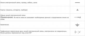
Designation on diagrams of radio components
Letter designations of elements on electrical diagrams
Designations on electrical diagrams of switches, sockets and light bulbs
Diode markings and designation diagram
Transformer designation on the diagram
What is dc current
The specific name is created from the English phrase “Direct Current” (dc is an abbreviation). This designation, literally translated, confirms the main feature of such a current - a constant direction.
Types of currents
For practical applications, a constant power supply or a sinusoidal signal is suitable. In these situations, it is easy to stabilize the source parameters and correctly calculate the electrical circuit, power unit or other connected equipment. Periodically repeating interference (pulsations) is eliminated by filtration. It is much more difficult to ensure a long working process when the current and voltage change in an arbitrary manner.
What is the designation for direct and alternating voltage?
Direct voltage or current is abbreviated DC, which stands for Direct current. On diagrams and electrical devices, it is also customary to indicate constant voltage with a simple straight line (—).
The alternating voltage icon is written in the form of a slightly different abbreviation ( – AC. If you decipher it, you get “Alternating current.” On the terminals of electrical appliances and distribution panels, as well as on diagrams, it can be depicted as a wavy line (~).
Important! If the network is designed to carry both types of electricity, it is marked as “AC/DC” and is indicated on the diagram by a double line (the upper line is straight and solid, and the lower line is straight and dotted).
Alternative designation of types of current and voltage in diagrams
Application categories for low-voltage switching devices
GOST R 50030.3-99
| Type of current | Application category | Typical Applications |
| Variable | AC-1 | Resistance circuits; non-inductive or low-inductive load |
| AC-2 | Starting and braking by counter-switching of electric motors with a wound rotor | |
| AC-3 | Direct starting of electric motors with squirrel-cage rotor, shutdown of rotating motors | |
| AC-4 | Starting and braking by back-switching of electric motors with a squirrel-cage rotor | |
| AC-11 | AC Solenoid Control | |
| AC-20 | Switching electrical circuits without current or with insignificant current | |
| AC-21 | Switching active loads, including moderate overloads | |
| AC-22 | Switching mixed resistive and inductive loads, including moderate overloads | |
| AC-23 | Switching motor loads or other highly inductive loads | |
| Variable and constant | A | Disabling electrical circuits under short circuit conditions in the absence of special time selectivity relative to series-connected downstream devices on the load side |
| B | Disabling electrical circuits under short circuit conditions in the presence of special time selectivity relative to series-connected downstream devices on the load side | |
| Constant | DC-1 | Electric resistance furnaces; non-inductive or low-inductive load |
| DC-2 | Starting shunt motors and switching off rotating shunt motors | |
| DC-3 | Starting electric motors with parallel excitation, turning off stationary or slowly rotating electric motors, back-on braking | |
| DC-4 | Starting series-wound electric motors and switching off rotating series-wound electric motors | |
| DC-5 | Starting electric motors with sequential excitation, switching off stationary or slowly rotating motors, back-on braking | |
| DC-11 | Control of DC electromagnets | |
| DC-20 | Switching a circuit on and off with no load or low current | |
| DC-21 | Switching active loads, including moderate overloads | |
| DC-22 | Switching mixed resistive and inductive loads, including moderate overloads such as shunt-wound motors | |
| DC-23 | Switching highly inductive loads, such as series-wound motors |
We advise you to study High Voltage Capacitors
Types of current
Designation (—) or DC (Direct Current).
) or AC (Alternating Current).
In the case of direct current (—), the current flows in one direction. Direct current is supplied, for example, by dry batteries, solar panels and batteries for devices with low current consumption. For the electrolysis of aluminum, electric arc welding and the operation of electrified railways, high-power direct current is required. It is created using AC rectification or using DC generators.
The technical direction of the current is that it flows from the contact with the “+” sign to the contact with the “–” sign.
In case of alternating current (
) distinguish between single-phase alternating current, three-phase alternating current and high-frequency current.
With alternating current, the current constantly changes its magnitude and direction. In the Western European power grid, the current changes its direction 50 times per second. The frequency of change of oscillations per second is called the frequency of the current. The unit of frequency is hertz (Hz). Single-phase alternating current requires a voltage conductor and a return conductor.
RMS voltage
The value of the electrical potential existing between two points of the electrical network can be determined by how much work was done over a certain period of time, or by the amount of heat released. In the case of alternating voltage, they proceed differently. Since its oscillation pattern has the shape of a sinusoidal curve, and the indicator takes its maximum value at the peak of the amplitude (and when moving from the plus zone of the curve to the minus voltage, the voltage is zero), an average indicator is used for calculations. This is what is called active, and it can be equated to the same value of direct voltage.
It is less than the maximum permissible indicator by an amount equal to the root of two from the latter (that is, approximately 1.4 times). For a network with a rated voltage of 220 V, the maximum will therefore be equal to 311 V. These indicators must be taken into account when selecting capacitors, diode components and other similar elements for installation in a particular system.
A sinusoidal voltage with an amplitude of 310 V is equivalent to a constant voltage, the value of which is 210 V
Edison's ideas
Modern life cannot be imagined without electricity. In order for it to serve civil and industrial purposes, it must not only be produced, but also delivered to the consumer. The first who decided to produce electricity in large quantities and transport it to factories, offices and households was the American entrepreneur Thomas Edison, one of the most influential inventors in the world.
To implement his idea, he designed and tested DC steam generators, electricity meters and distribution network elements. Carrying out the first electrification of lighting was not easy at that time. The owners of gas companies viewed Edison as a dangerous competitor who could jeopardize the existence of their enterprises. But nothing could stop the inventor. Neither the colossal cost of laying cables in the sidewalks, nor accidents during testing prevented him from launching the first lighting network of five thousand lamps in September 1882.
https://youtube.com/watch?v=dwaSF3W4TxU
After 5 years, more than 50 Edison power plants were already operating. Despite his great success, the inventor was unable to expand the geography of his electrical networks throughout the world. Residents of the areas where the power plants were located complained about smoke and soot, and forced the closure of Edison's production facilities. Thus, the first generation of coal-fired power plants eventually ceased operation, giving way to thousands of new ones generating AC.
How does tension work?
The general concept of electric current is the directed movement of charged particles. These particles are electrons, the movement of which occurs under the influence of an electric field. The more charges need to be moved, the more work is done by the field. This work is affected not only by current, but also by voltage.
The physical meaning of this value is that the work done by the current in any section of the circuit is correlated with the amount of charge that passes through this section. In the process of this work, a positive charge moves from a point where there is a small potential to a point with a high potential. Thus, voltage is defined as a potential difference or electromotive force, and work itself is energy.
To clearly explain the physical meaning of stress, you need to refer to the example of a hose filled with water. In this case, the volume of water will play the role of current strength, and its pressure will be equivalent to voltage. When water moves without a tip, it moves freely and in large quantities through the hose, creating low pressure. If you press the end of the hose with your finger, the volume will decrease while the water pressure increases. The jet itself will travel a much greater distance.
The same thing happens in electricity. The strength of the current is determined by the number or volume of electrons moving through the conductor. The voltage value is essentially the force with which those electrons are pushed through. It follows that, given the same voltage, a conductor that conducts a larger amount of current must also have a larger diameter.
What voltage icon
Voltage refers to the flow of electrically charged particles through a conductor of a certain cross-section and is usually denoted as "U". If the voltage in the network is constant, then a symbol of a straight line or two lines is placed next to the Latin letter (the upper solid straight line and the lower dotted line). For multimeters and other devices related to voltage measurement, the Latin letter “V” is used, which denotes the unit of voltage measurement - Volt. The meaning of the lines is retained.
It will be interesting➡ What is a short circuit
You may be interested in this Transition from 380 to 220 volts
Important! Many people believe that voltage is designated as “E”, but this is not true. “E” is the electrodynamic force (EMF) of the conductor power source.
Indication of the type of current on a multimeter
Thus, the marking of wires, terminals of electrical appliances and circuits is completely clear and understandable. It indicates the current and voltage with which a particular network or device operates. Every adult can learn to read electrical diagrams in just a few days, since it is enough to just study the basic markings, as well as the designations of direct and alternating voltage.