Standard range of resistor powers and their designation in diagrams
Please note that resistors of the same value can have different power dissipations. This parameter depends on the manufacturing technology and case material. There is a certain number of capacities and their graphic designation according to GOST.
The graphical designation of resistor power in the diagram is dashes and Roman numerals printed on the surface of the resistance. The smallest standard value is 0.05 W, the largest is 25 W, but there are also more powerful ones. But this is a special element base and is not found in household equipment.
How to choose a replacement resistor
If you need to change a resistor, you need to take either the same power or higher. In no case lower - after all, the resistor is already out of order. This usually happens due to overheating. So installing a lower power resistor is excluded. Or rather, you can install it. But be prepared for the fact that you will have to change it again soon.
If space on the board allows, it is better to install a part with greater power dissipation than that of the part being replaced. Or raise the resistor of the same power higher (you don’t have to cut the leads at all) - for better cooling. In general, when replacing a resistor, take the power either the same or one step higher.
Source
How to calculate the power of a resistor in a circuit
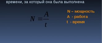
To calculate the power of resistors in a circuit, in addition to resistance (R), you need to know the current strength (I). Based on these data, the power can be calculated. The formula is usual: P = I² * R. The square of the current strength is multiplied by the resistance. We substitute the current strength in Amperes, the resistance in Ohms.
If the denomination is written in kilo-ohms (kOhm) or mega-ohm (mOhm), we convert it to Ohms. This is important, otherwise the number will be wrong.
Diagram of series connection of resistors
For example, consider the diagram in the figure above. A series connection of resistances is characterized by the fact that the same current flows through each individual resistor in the circuit. This means the resistance power will be the same. Series connected resistances are simply summed up: 200 Ohms + 100 Ohms + 51 Ohms + 39 Ohms = 390 Ohms. We calculate the current using the formula: I = U/R. We substitute the data: I = 100 V / 390 Ohm = 0.256 A.
Based on the calculated data, we determine the total power of the resistances: P = 0.256² * 390 Ohm = 25.549 W. The power of each resistor is calculated in the same way. For example, let's calculate the power of resistor R2 in the diagram. We know the current, its nominal value too. We get: 0.256A² * 100 Ohm = 6.55 W. That is, the power of this resistor must be at least 7 W. It’s definitely not worth taking with a lower power - it will quickly burn out. If the design of the device allows, then you can install a resistor of higher power, for example, 10 W.
There are MLT series resistors in which the heat dissipation power is indicated immediately after the series name without any letters. In this case, MLT-2 means that the power of this instance is 2 W, and the nominal value is 6.8 kOhm.
For a parallel connection, the calculation is similar. You just need to correctly calculate the current, but that’s a topic for another article. And the formula for calculating the power of a resistor does not depend on the type of connection.
Resistor power - what it is, what it affects
The power dissipation of the resistor element is max. current that can withstand resistance for a long time without compromising performance.
That is, this parameter must be selected for each electrical circuit separately. Power is calculated using the following formula: P = I * R.
The physically dissipated parameter of a resistor device is the amount of heat that its body can “transfer” without burning. Power primarily affects the reliability of the resistor device.
Important! All resistor components, regardless of the set parameters, operate on the basis of Ohm's law, this is the main key through which the voltage is determined. Voltage drop is the difference in input and output values. Inside the mechanism, the flowing current changes or is limited - electrons collide with the inhomogeneous structure of the conductor material.
Checking the resistor with a multimeter
A black probe is inserted into the COM connector, and a red one into the VΩ connector. VΩ is a measurement of voltage and resistance.
We switch the multimeter to resistance measurement mode. Diode testing will not help. The continuity test only measures voltage drop, not resistance. We start with a small value of 200 ohms.
A dot on the screen shows the measurement limit. Here the limit selected is 20 kOhm.
The multimeter shows 2.7 kOhm. When taking measurements, you must not touch two metal bases of the probes at the same time. Your body may shunt the part being measured and the parting reading will be false.
A faulty resistor is the most difficult to diagnose. It can be either broken (short circuit) or broken. The problem is that if you don't know the markings or don't have a diagram, it will be more difficult to identify the faulty part.
A broken resistor will be determined by a multimeter as having 0 resistance. And in diode testing mode, the multimeter will start beeping. However, if the actual resistance of the resistor was 1 Ohm, then the device may beep, and in resistance measurement mode it will show errors.
The same thing applies to resistors whose resistance ratings are higher than that of the device being measured. You can also check it using a diode test. If the resistor is working properly, the diode continuity test will not squeak, it will show a voltage drop. But there is a problem here too.
How to determine by appearance
The circuit diagram shows the required resistor power - everything is clear here. But how can you determine the resistance power by its appearance on the printed circuit board? In general, the larger the case size, the more heat it dissipates. On fairly large resistances, the nominal resistance and its power in watts are indicated.
There is some confusion here, but it's not all that bad. On domestic resistances they put the letter B next to the number. In foreign ones they put W. But these letters are not always there. In imported ones there may be a V or SW before the number. Imported ones may also have the letter B, but domestic MLTs may have nothing or the letter W. A confusing story, of course. But with experience, at least some clarity appears.
But there are small resistors on which even the nominal value can hardly fit. In imported ones it is applied with colored stripes. How can you find out their dissipation power?
In the old GOST there was a table of correspondence between sizes and capacities. Domestic resistors are still made in accordance with this table. By the way, there are also imported ones, but they are slightly smaller in size than domestic ones. However, they can also be identified. If you are in doubt about which group a particular specimen belongs to, it is better to assume that it has a lower ability to dissipate heat. There is less chance that the part will burn out soon.
| Resistor type | Diameter, mm | Length, mm | Power dissipation, W |
| Sun | 2,5 | 7,0 | 0,125 |
| ULM, VS | 5,5 | 16,5 | 0,25 |
| Sun | 5,5 | 26,5 | 0,5 |
| 7,6 | 30,5 | 1 | |
| 9,8 | 48,5 | 2 | |
| 25 | 75 | 5 | |
| 30 | 120 | 10 | |
| CMM | 1,8 | 3,8 | 0,05 |
| 2,5 | 8 | 0,125 | |
| MLT | 2 | 6 | 0,125 |
| 3 | 7 | 0,125 | |
| 4,2 | 10,8 | 0,5 | |
| 6,6 | 13 | 1 | |
| 8,6 | 18,5 | 2 |
It seems clear with the sizes of the resistances and their power. Not everything is so simple. There are large resistors with low dissipation capacity and vice versa. But in such cases, this parameter is indicated in the labeling.
Power of SMD resistors
SMD components are designed for surface mounting and have miniature dimensions. The power of SMD resistors is determined by size. It is also in the specifications, but you need to know the series and manufacturer. The power table for SMD resistors contains the most common values.
| Code imperial | Metric code | Length inch/mm | Width inch/mm | Height inch/mm | Power, W |
| 0201 | 0603 | 0,024/0,6 | 0,012/0,3 | 0,01/0,25 | 1/20 (0,05) |
| 0402 | 1005 | 0,04/1,0 | 0,02/0,5 | 0,014/0,35 | 1/16 (0,062) |
| 0603 | 1608 | 0,06/1,55 | 0,03/0,85 | 0,018/0,45 | 1/10 (0,10) |
| 0805 | 2112 | 0,08/2,0 | 0,05/1,2 | 0,018/0,45 | 1/8 (0,125) |
| 1206 | 3216 | 0,12/3,2 | 0,06/1,6 | 0,022/0,55 | 1/4 (0,25) |
| 1210 | 3225 | 0,12/3,2 | 0,10/2,5 | 0,022/0,55 | 1/2 (0,50) |
| 1218 | 3246 | 0,12/3,2 | 0,18/4,6 | 0,022/0,55 | 1,0 |
| 2010 | 5025 | 0,20/2,0 | 0,10/2,5 | 0,024/0,6 | 3/4 (0,75) |
| 2512 | 6332 | 0,25/6,3 | 0,12/3,2 | 0,024/0,6 | 1,0 |
In general, this type of radio elements has no other operational way of determining the current at which they can operate, other than by size. You can recognize them by their characteristics, but finding them is not always easy.
