Classification of power lines
Such installations can be classified according to purpose, voltage, operating mode, and so on. Each of these points is described in detail below.
By type of current
In recent years, electricity transmission has been carried out mainly using alternating current. This method is popular because most electricity sources produce alternating voltage (with the exception of individual sources, such as solar panels), and the main consumer is alternating current installations.
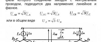
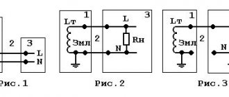
Overhead line wiring diagram
Very often, DC power transmission is more favorable. To reduce losses in power lines, when transmitting electrical energy on any type of current, the voltage is raised using transformers (CTs).
You might be interested in this. Features of the VVG cable
Also, when transferring from an installation to a consumer using direct current, it is necessary to convert electrical energy from alternating current to direct current; for this, there are special rectifiers.
By purpose
Based on their purpose, power lines can be divided into several types. By distance the lines are divided into:
- ultra-long-range. On such power lines the voltage will be over 500 kilovolts. They are used to move energy over long distances. Basically, they are necessary to combine different energy systems or their elements;
Classification of overhead power lines
- main lines. Such lines come with a voltage of 220 or 380 kV. They unite large energy centers or different installations with each other;
- distribution This type includes systems with voltages of 35, 110 and 150 kV. Used to unite districts and small supply centers;
- supplying electrical energy to people. Voltage - no higher than 20 kV, the most popular types are 6 and 10 kV. These power lines bring energy to distribution points and then to people’s homes.
By voltage
Based on the base voltage, such power lines are mainly divided into two main groups. With low voltage up to 1 kV. GOSTs indicate four main voltages, 40, 220, 380 and 660 V.
With voltage above 1 kV. GOST describes 12 parameters here, average indicators - from 3 to 35 kV, high - from 100 to 220 kV, the highest - 330, 500 and 700 kV and ultra-high - more than 1 MV. It is also called high voltage.
Power line 330 kV
On the system of functioning of neutrals in electrical installations
Such installations can be divided into four networks:
- three-phase, in which there is no grounding. This scheme is mainly used in networks with voltages up to 35 kV, where small currents move;
- three-phase, in which there is grounding using inductance. This installation is also called resonant-grounded type. In such overhead lines, a voltage of 3-35 kV is used, where large currents move;
- three-phase, in which there is full grounding. This mode of neutral operation is used in overhead lines with medium and high voltages. Here you need to use current transformers;
- solidly grounded neutral. Here overhead lines operate with voltages less than 1.0 kV or more than 220 kV.
Installation process
According to the operating mode depending on the mechanical condition
There is also such a division of power lines, where the external state of all parts of the installation is provided. These are power lines in good condition where the cables, posts and other components are almost new. The main emphasis is on the quality of cables and ropes; they should not be subject to mechanical damage.
There is also an emergency situation where the quality of cables and ropes is quite low. Such installations require immediate repair.
- power lines are in good operating condition - all components are new and not damaged;
- emergency lines - in case of obvious visible damage to the wires;
- installation view lines - during the installation of racks, cables and ropes.
You might be interested in this Features of cross-linked polyethylene cable
Only an experienced electrician needs to determine the condition of power lines.
If the installation is in an emergency, this can lead to a number of consequences. For example, energy will not be supplied continuously, a short circuit is possible, and exposed wires may cause a fire if they come into contact. If the power line was not installed on time and irreparable consequences occurred, this could result in huge fines.
Underground cable power lines
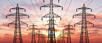
Purpose of overhead power lines
Such overhead lines are called installations that are used to move and distribute electrical energy along cables located in the open air and held using special racks. Overhead lines are installed and used in a wide variety of weather conditions and geographic areas, and are prone to atmospheric influences (precipitation, temperature changes, winds).
Therefore, overhead lines must be installed taking into account weather factors, air pollution, installation requirements (for a city, field, village), etc. The installation must comply with a number of rules and regulations:
- economical cost;
- high electrical conductivity, strength of the ropes and racks used;
- resistance to mechanical damage and corrosion;
- be safe for nature and people, do not occupy a lot of free territory.
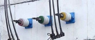
What do insulators look like?
What do the inscriptions on overhead line supports mean?
Surely many have seen the inscriptions on power transmission poles in the form of letters and numbers, but not everyone knows what they mean.
Photo 10. Designations on power line supports.
They mean the following: a capital letter indicates the voltage class, for example T-35 kV, S-110 kV, D-220 kV. The number after the letter indicates the line number, the second number indicates the serial number of the support.
T means 35 kV. 45 is the line number. 105 is the serial number of the support. This method of determining power line voltage by the number of insulators in a garland is not accurate and does not provide a 100% guarantee. Russia is a huge country, therefore, for different operating conditions of power lines (cleanliness of the surrounding air, humidity, etc.), designers calculated different numbers of insulators and used different types of supports. But if you approach the issue comprehensively and determine the voltage according to all the criteria described in the article, then you can quite accurately determine the voltage class. If you are far from the electric power industry, then for a 100% determination of the power line voltage, it is still better for you to contact your local energy company.
For an experienced electrician who has been working with overhead power lines for many years, it will not be difficult to visually determine the voltage of an overhead line by the type of insulators, supports, and the number of wires in the line without any instruments. Although in most cases, to determine the voltage on an overhead line, you just need to look at the insulators. After reading this article, you will also be able to easily determine the voltage of overhead lines using insulators.
Photo 1. Pin insulators for voltage 0.4, 6-10, 35 kV.
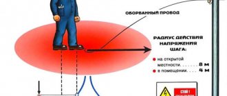
Every person should know this! But why, why does a person far from the electric power industry need to be able to determine the voltage of an overhead power line by the appearance of the insulators and the number of insulators in the overhead power line garland? The answer is obvious, it's all about electrical safety. After all, for each voltage class of overhead lines, there are minimum permissible distances, closer than which approaching the overhead line wires is deadly.
In my practice, there were several accidents associated with the inability to determine the voltage class of overhead lines. Therefore, below is a table from the safety rules, which indicates the minimum permissible distances, the closer of which it is deadly to approach live parts that are energized.
Table 1. Permissible distances to live parts that are energized.
| Voltage, kV | Distance from people | Distance from mechanisms |
| up to 1 per overhead line | ||
| up to 1 in other electrical installations | not standardized (no touching) |
*D.C.
Case one
occurred at the construction site of a country house. For some unknown reason, there was no electricity at the construction site; a 10 kV overhead line ran near the unfinished house. Two workers decided to power an extension cord from this overhead line to connect power tools. After stripping two wires on the extension cord and making hooks, they decided to use a stick to hook them to the wires. On a 0.4 kV overhead line, this scheme would work. But since the voltage of the overhead line was 10 kV, one worker received serious electrical injuries, and miraculously survived.
Second case
occurred on the territory of the production base while unloading pipes. A working slinger was unloading metal pipes from a truck using a truck crane in the coverage area of a 110 kV overhead line. During unloading, the pipes bent so that one end came dangerously close to the wires. And even despite the fact that there was no direct contact of the wires with the load, a breakdown occurred due to the high voltage and the worker died. After all, you can be killed by electric shock from a 110 kV overhead line even without touching the wires, you just need to get close to them. I think it’s now clear why it is so important to be able to determine the voltage of overhead lines by the type of insulators.
The main principle here is that the higher the power line voltage, the greater the number of insulators in the garland. By the way, the highest voltage power line in the world is located in Russia, its voltage is 1150 kV.
The first type of line whose voltage you need to know in person is a 0.4 kV overhead line. These overhead line insulators are the smallest, usually pin insulators made of porcelain or glass, mounted on steel hooks. The number of wires in such a line can be either two, if it is 220V, or 4 or more, if it is 380V.
Photo 2. Wooden support of 0.4 kV overhead line.
The second type is VL-6 and 10 kV; outwardly they do not differ. 6 kV overhead lines are gradually becoming a thing of the past, giving way to 10 kV overhead lines. The insulators of these lines are usually pin-type, but are noticeably larger than 0.4 kV insulators. Suspension insulators, one or two in a garland, can be used on corner supports. They are also made of glass or porcelain, and are mounted on steel hooks. So: the main visual difference between the 0.4 kV overhead line and the 6, 10 kV overhead line is the larger insulators, as well as only three wires in the line.
Photo 3. Wooden support of 10 kV overhead line.
The third type is 35kV overhead line. Suspended insulators, or pin insulators, are already used here, but of a much larger size. The number of pendant insulators in a garland can be from three to five, depending on the support and type of insulators. The supports can be either concrete or made of metal structures, as well as wood, but then it will also be a structure, and not just a pole.
Photo 4. Wooden support of 35 kV overhead line.
110 kV overhead line from 6 insulators in a garland. Each phase, single wire. The supports can be reinforced concrete, wooden (almost never used) or assembled from metal structures.
Photo 5. Reinforced concrete support of 110 kV overhead line.
220 kV overhead line from 10 insulators in a garland. Each phase is carried out with a thick single wire. With voltages above 220 kV, supports are assembled from metal structures or reinforced concrete.
Photo 6. 220 kV power line support.
330 kV overhead line from 14 insulators in a garland. There are two wires in each phase. The security zone of these overhead power lines is 30 meters on both sides of the outermost wires.
Photo 7. 330 kV transmission line support.
500 kV overhead line from 20 insulators in a garland, each phase is carried out with a triple wire arranged in a triangle. Security zone 40 meters.
Photo 8. 500 kV transmission line support.
750 kV overhead line from 20 insulators in a garland. Each phase has 4 or 5 wires arranged in a square or ring. Security zone 55 meters.
Photo 9. 750 kV transmission line support.
Table 2. Number of insulators in an overhead line garland.
| Type of insulator according to GOST |
| PF6-A (P-4.5) |
| PF6-B (PM-4.5) |
| PF6-V (PFE-4.5) |
| PF20-A (PFE-16) |
| PS6-A (PS-4.5) |
| PS-11 (PS-8.5) |
Technical characteristics of power lines
Main parameters of power lines:
- l - gaps between racks or supports of power lines;
- dd - space between adjacent cable lines;
- λλ - can be deciphered as the length of the power line garland;
- HH - stand height;
- hh is the smallest permitted distance from the low level of the cable to the ground.
Not everyone can decipher all the characteristics of installations. Therefore, you can turn to a professional for help.
Below is a table of power lines updated in 2010. A more complete description can be found on electrical forums.
| Rated voltage, kV | ||||||
| 40 | 115 | 220 | 380 | 500 | 700 | |
| Spacing l, m | 160-210 | 170-240 | 240-360 | 300-440 | 330-440 | 350-550 |
| Space d, m | 3,0 | 4,5 | 7,5 | 9,0 | 11,0 | 18,5 |
| Garland length X, m | 0,8-1,0 | 1,4-1,7 | 2,3-2,8 | 3,0-3,4 | 4,6-5,0 | 6,8-7,8 |
| Stand height H, m | 11-22 | 14-32 | 23-42 | 26-44 | 28-33 | 39-42 |
| Line parameter h, m | 6-7 | 7-8 | 7-8 | 8-11 | 8-14 | 12-24 |
| Number of cables per phase* | 1 | 1 | 2 | 2 | 3 | 4-6 |
| Volume of wire sections, mm2 | 60-185 | 70-240 | 250-400 | 250-400 | 300-500 | 250-700 |
You might be interested in Wire cross-section
Basic Installation Elements
To reduce the number of outages that occur during bad weather conditions, power plant lines are equipped with lightning protection ropes, which are installed on racks above the cables and are used to suppress direct lightning strikes on power lines. They are similar to metal galvanized multi-wire cables or special reinforced aluminum cables of small cross-section.
Such lightning protection devices are produced and used with fiber-optic cores built into their tubular rods, which provide multi-channel communication. In areas with constantly recurring and severe frosts, ice is deposited on wires and accidents occur due to penetration of overhead lines when sagging ropes and cables approach.
The operating temperature of power lines ranges from 150 to 200 degrees. The wires have no insulation inside. They must have a high degree of conductivity, as well as resistance to mechanical damage.
The following describes which power lines are used to transmit electricity.
Two main types