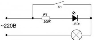
Any lover of homemade products and electronics use diodes as indicators, or as lighting effects and lighting. In order for the LED device to glow, you need to connect it correctly. You already know that a diode only conducts current in one direction. Therefore, before soldering, you need to determine where the anode and cathode of the LED are.
You may see two LED designations on a circuit diagram.
The triangular half of the designation is the anode, and the vertical line is the cathode. The two arrows indicate that the diode is emitting light. So, the diagram indicates the anode and cathode of the diode, how to find it on a real element?
Pinout of 5mm diodes
To connect the diodes as in the diagram, you need to determine where the plus and minus of the LED are. First, let's look at the example of common low-power 5 mm diodes.
The figure above shows: A - anode, K - cathode and schematic symbol.
Pay attention to the flask. You can see two parts in it - this is a small metal anode, and a wide part that looks like a bowl is the cathode. The plus is connected to the anode, and the minus to the cathode.
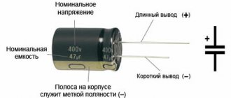
If you are using new LED elements, it is even easier for you to determine their pinout. The length of the legs will help determine the polarity of the LED. Manufacturers make short and long legs. The plus is always longer than the minus!
If you are not soldering a new diode, then its plus and minus are the same length. In this case, a tester or a simple multimeter will help to determine the plus and minus.
Power supply polarity detection
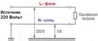
For quick testing, you will need a current source with a voltage of 3 to 6 volts (battery or accumulator), a resistor with a resistance of 300–470 Ohms of any power and, directly, an LED. Due to the low value of the reverse voltage, it is not recommended to test the LED from a source with a voltage greater than 6 V. The resistor must be soldered to one of the legs and then touch the contacts of the power source. By touching the anode to the plus and the cathode to the minus, a serviceable emitting diode will glow.
Repair shop workers are often armed with dead three-volt batteries from a computer motherboard or digital wall clock (CR2032). After making sure that the current of such a battery does not exceed 30 mA, it is briefly inserted between the terminals of the LED without a resistor. Plus and minus are determined by its glow.
How to determine the anode and cathode of diodes 1W or more
In flashlights and spotlights, 5mm samples are used less and less; they have been replaced by powerful elements with a power of 1 watt or more or SMD. To understand where the plus and minus are on a powerful LED, you need to carefully look at the element from all sides.
The most common models in such a case have a power of 0.5 watts. The polarity mark is circled in red in the figure. In this case, the anode of the 1W LED is marked with a plus sign.
Results.
The described methods have their strengths and weaknesses. It is impossible to check the performance of the LED using technical documentation or visually. Testing using voltage requires special care. But a powerful LED cannot always be measured with a multimeter. To work successfully, an electrical engineer should master all the methods and apply them as necessary.
- Related Posts
- TOP 10 LED lamps of 2021
- Relevance of LED lighting in 2021: efficiency, pros and cons
- Which lamp to choose for plants - the best options
How to find out the polarity of SMD?
SMDs are actively used in practically any technology:
- Light bulbs;
- LED strips;
- flashlights;
- indication of something.
You won’t be able to see their insides, so you need to either use testing devices or rely on the LED housing.
For example, on the SMD 5050 case there is a mark on the corner in the form of a cut. All pins located on the tag side are cathodes. Its body contains three crystals, this is necessary to achieve high brightness.
A similar designation for SMD 3528 also indicates the cathode, take a look at this photo of the LED strip.
The marking of the SMD 5630 pins is similar - the cut indicates the cathode. It can also be recognized by the fact that the heat sink on the bottom of the case is shifted towards the anode.
How to determine where the plus and minus are
It is almost impossible to determine the polarity of the diode visually. If you make a mistake, the circuit will not work. The location of the diode's poles can be determined in the following ways:
- visually;
- using a multimeter;
- according to technical documentation;
- by installation according to a simple scheme.
Determine visually
To accurately distinguish the cathode from the anode, the manufacturer of diode light bulbs began to make the cathode contact shorter than the anode. There is also a small letter “k” near the cathode. But to understand where something is based on the length of the wires is only possible in new diodes; in old, already used parts, the wires can be broken off. Some manufacturers put a dot near the cathode. If you turn the current back on, a breakdown will occur and the device will have to be thrown away.
It is convenient to determine the polarity of cylindrical diodes. This can be done using the following signs. The housing contains electrodes with different areas. The cathode has a much larger electrode than the anode. The output with the large electrode is negative.
Polarity is most easily determined with powerful diodes. They are large and you can easily put plus and minus on their body.
We use a multimeter
A more reliable way is to test with a multimeter. The device selects the “ohmmeter” operating mode. Now the multimeter can measure the resistance level. The device has 2 legs, they must be brought to the plus and minus. Black is in contact with the minus, red is in contact with the plus.
If the diode contacts are determined correctly, the device will show 1.7 kOhm. If there is an error, the device will give a much higher reading. If the resistance is less than 1.7, then the diode is damaged and must be replaced. Some taxi drivers have a special mode that allows you to check the LEDs. This test method only works with red and green diodes.
Blue and white will only react if you apply a voltage of 3 volts to them. These bulbs can only be tested using special multimeters such as DT830.
Interesting video on the topic:
By supplying power
In cases where you do not have a multimeter, the plus and minus of the LED are determined in a simple, but no less effective way. The test requires a battery and a resistor. The battery can be replaced with a rechargeable battery. The resistor in this case will protect the element from breakdown. Some craftsmen use a special socket; its purpose is to check the serviceability of transistors.
In a situation where it is impossible to determine the anode and cathode of the diode either by eye or with a multimeter, they resort to another method. The diode is connected briefly to the electrical circuit. Then everything is simple. If the light comes on, then the outputs are identified correctly; if not, everything will remain unchanged.
According to technical documentation
In many diagrams, the LED is drawn as a circle with a triangle inside, with the cathode shown as a minus and the anode as a plus. In the diagrams, all pins must be designated so that the one who will assemble this circuit knows how to connect the diode to the circuit.
Determining the polarity of an LED using technical documents is always easy, but you don’t always have them on hand. Especially when these products are purchased by users through stores. But there is another way, for this you need to know the LED number. There is a lot of information on the Internet not only on the design of diodes. There are detailed diagrams and drawings indicating all the parameters. These diagrams will necessarily indicate the location of the diodes.
Determine polarity with a multimeter
When replacing diodes with new ones, you can determine the plus and minus of your device's power supply from the board.
LEDs in spotlights and lamps are usually soldered onto an aluminum plate, on top of which a dielectric and current-carrying tracks are applied. It usually has a white coating on top; it often contains information about the characteristics of the power source, and sometimes the pinout.
But how can you find out the polarity of an LED in a light bulb or matrix if there is no information on the board?
For example, on this board the poles of each LED are indicated and their name is 5630.
To check for serviceability and determine the plus and minus of the LED, use a multimeter. We connect the black probe to minus, com or a socket with a grounding sign. The designation may differ depending on the multimeter model.
Next, select the Ohmmeter mode or the diode test mode. Then we connect the multimeter probes one by one to the diode terminals, first in one order, and then vice versa. When at least some values appear on the screen, or the diode lights up, it means the polarity is correct. In diode testing mode, the values are 500-1200 mV.
In measurement mode, the values will be similar to those in the figure. A unit in the leftmost digit indicates exceeding the limit, or infinity.
How does a diode work?
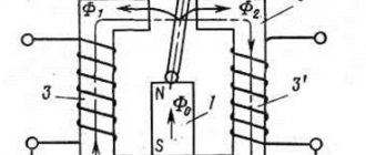
The basis of the operation of a diode is the different conductivity of two semiconductors (this article is only about them) connected together.
An n-type semiconductor allows electrons to pass through, while a p-type semiconductor allows holes to pass through. If the polarity of the diode is observed, that is, minus is applied to the n-type, and plus is applied to the p-type, then forward voltage is applied to each type and the diode is open. If the power signs are reversed, that is, reverse voltage is applied, the diode will be closed. Why does this happen?
At the junction of two semiconductors with different conductivities, a small bias region is formed. This is when electrons from the n-type partially move into the p-type region. There are no free electrons or holes in this place. When direct voltage is connected, the lack of electrons and holes is compensated by the power source, that is, the zone closed to the transition of charge carriers almost disappears.
Electrons, under the influence of the electromotive force acting in the power source, jumping from hole to hole, pass through the p-type section and land on the conductor.
What happens if you change the polarity of the power supply: connect plus to the n-type section, and minus to the p-type? In this case, the electrons in the n-type region will move towards the power source, expanding the closed area, thereby increasing the internal resistance of the diode . In this case, the diode will be closed.
Of course, if you increase the voltage on the diode, then electrons will be able to pass through the saturated region and current will flow through the diode. Some diodes operate in this mode; they are called zener diodes.
But rectifier diodes do not “like” such conditions and may fail. And for zener diodes, not only the reverse voltage is specified, but also the current at which they can operate. If you exceed the specified values, an irreversible process may occur - thermal breakdown and the device will fail.
Other ways to determine polarity
The easiest option for determining where the LED is plus is batteries from the motherboard, size CR2032.
Its voltage is about 3 volts, which is quite enough to light the diode. Connect the LED, depending on its glow you will determine the location of its pins. This way you can test any diode. However, this is not very convenient.
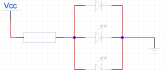
You can assemble a simple probe for LEDs, and not only determine their polarity, but also the operating voltage.
Homemade probe circuit
When the LED is connected correctly, a current of about 5-6 milliamps will flow through it, which is safe for any LED. The voltmeter will show the voltage drop across the LED at this current. If the polarity of the LED and the probe match, it will light up and you will determine the pinout.
You need to know the operating voltage, since it differs depending on the type of LED and its color (red takes less than 2 volts).
And the last method is shown in the photo below.
Turn on the Hfe mode on the tester, insert the LED into the connector for testing transistors, into the area marked as PNP, into holes E and C, with the long leg in E. This way you can check the functionality of the LED and its pinout.
If the LED is made in a different form, for example, smd 5050, you can use this method simply - insert regular sewing needles into E and C, and touch them with the LED contacts.
Any lover of electronics, and even homemade products in general, needs to know how to determine the polarity of an LED and how to check them.
Be careful when choosing the elements of your circuit. At best, they will simply fail faster, and at worst, they will instantly burst into blue flame.
Please rate the article. We tried our best:)
Did you like the article? Tell us about her! You will help us a lot :)
What you need to know about replacing lamps with LEDs
If you decide to replace the standard optics with LED ones, I hasten to warn you about some possible difficulties that arise during the replacement process. The first thing I would like to remind you about is the polarity of LEDs. Before connecting LED optics of any power, it is very important to find the positive and negative terminals on the contact group. For a regular round light bulb base, the negative wire is suitable. For the contact at the end - “positive”. However, in many brands of cars, including domestic ones, another option for turning on the lamps is possible. As for the contacts of the interior lighting, trunk or glove box, in many car models it is almost impossible to determine the polarity of the contacts “by eye”. Incorrect switching on of an LED optical device can lead to its immediate failure. Therefore, before turning it on for the first time, I strongly recommend that you first ring the contacts to determine the polarity and, if necessary, change them in accordance with the polarity of the contacts of the LED optical device.
If you connect an LED strip with the ability to control the brightness and color of the glow, you must additionally purchase a control device. When installing the tape in places that exclude moisture, for example, in the interior, I recommend attaching it with double-sided tape. When installing the tape on the bottom, you need to think in advance about fastening and protecting it from gravel, dirt and moisture. It is necessary to remember that the installation of LED optics instead of standard high and low beam lamps is legally prohibited. Installation of inappropriate lighting equipment is also punishable by administrative law. Therefore, before purchasing LED optics, you should ask the seller whether they meet all the necessary standards and requirements. The glow color of modern SMD LEDs and LED matrices does not match the color of their crystal. So, if a seller shows you LED optics with yellow crystals and claims that they are white, do not be confused. When switched on for a test, these LED lamps light up with bright light, similar in temperature to daylight. When purchasing LED optics of any type, be sure to find out about the polarity of their connection and request testing at a special stand.