Like any equipment or technique, over time, electrical cables of various types begin to fail. One of the methods for determining the safety margin of a cable and identifying defects is to measure the insulation resistance. This article explains what it is, when and how it is done.
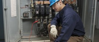
Electrical wiring inspection
Each organization that manages electrical installations must have a person responsible for electrical equipment. His responsibilities include drawing up scheduled maintenance work for the repair of this equipment, as well as conducting periodic tests and measurements, and inspecting electrical wiring. The frequency of such measurements, as a rule, is based on the requirements of PTEEP. For example, regarding the measurement of insulation resistance, it says that tests should be carried out once every 3 years.
What is insulation resistance measurement
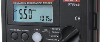
Measuring insulation resistance with a megohmmeter
This is a measurement with a special device (megaohmmeter) of the resistance between two points of an electrical installation, which characterizes the leakage current between these points when DC voltage is applied. The result of the measurement is a value expressed in MOhm (megaOhm). The measurement is carried out by a device - a megohmmeter, the principle of which is to measure the leakage current that occurs under the influence of a constant pulsating voltage on an electrical installation. Modern megohmmeters provide different voltage levels for testing different equipment.
How is resistance measured?
The procedure for checking the condition of the insulating layer depends on the type of electrical conductor being tested. At the initial stage, identical actions are performed:
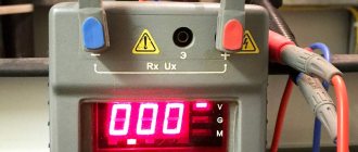
- The performance of the megohmmeter is checked. You will need to connect the two clamps of the device and take a measurement. The device should show zero. Then the ends of the wires of the measuring device are pulled apart and a measurement is taken. If the result is infinity, then the device is working.
- Measurements are taken from the side of the cable line where portable grounding is installed. During the work it is necessary to use dielectric gloves.
- At the other end of the cable line, the conductor cores should be spread apart. To ensure the safety of people from electric shock during testing, a person should be placed to warn of the danger.
At the final stage, it is necessary to compare the results obtained with acceptable values and draw up a protocol. It reflects the sequence of actions performed, the measuring instruments used, the temperature conditions and a conclusion about the condition of the electrical conductor.
Methodology for measuring insulation resistance of high-voltage power cables
It is necessary to ring high-voltage conductors using a 2500 V megohmmeter. The sequence of actions is as follows:
- One end of the measuring device clings to the ground loop, and the other to phase “A” of the cable.
- The grounding conductor is removed from phase “A” and measurements are taken for 60 seconds.
- Next, you will need to install the grounding to phase “A” and remove the megohmmeter clamp.
- In the future, similar operations are carried out for phases “B” and “C”.
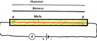
High voltage cable insulation measurement circuit
For a significant cable line length, tests are carried out taking into account the absorption coefficient. You will need to record the device readings after 15 and 60 seconds of measurements. The ratio of the resistance value after 60 seconds to the reading after 15 seconds must be at least 1.3. If the value is lower, it is concluded that the insulating layer is moistened. To eliminate the problem, you will need to dry the conductor.
Methodology for measuring insulation resistance of low-voltage power cables
To carry out the work, you will need to use a 1000 V megohmmeter. After completing the initial steps, you must begin the following activities:
- The resistance between the phases of the cable line is measured, respectively “A” - “B”, “B” - “C” and “A” - “C”.
- The insulation of the cable phases relative to the neutral wire (N) is checked one by one.
- Next, alternate measurements are taken between each phase and the ground loop (PE) when checking a five-wire conductor.
- The neutral wire is disconnected from the zero bus and a measurement is made between N and PE.
Measuring the insulation resistance between cable cores
After each test, the potential should be removed by installing a ground connection.
Methodology for measuring insulation resistance of control cables
The process of checking the condition of the insulating layer of the specified category of conductive cores is identical to the previous paragraph, with one exception. The cable cores that are not involved in the test must be short-circuited and connected to the ground loop.
Allowable resistance for various equipment
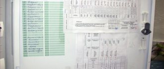
Electrical wiring insulation resistance measurements: frequency
The main guiding document is the PTEEP, which provides the frequency of tests, the magnitude of the test voltage and the standard resistance value for each type of electrical equipment (PTEEP Appendix 3.1, Table 37). Below is an excerpt from the document.
Do not confuse the resistance of electrical cables with the resistance of a coaxial cable and the characteristic impedance of the cable, because This applies to radio engineering and there are different principles of approach to permissible values.
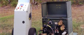
7.1. Before testing the power cable with increased voltage, it is necessary to accurately establish the beginning and end of the test cable and ensure the safety of the work. 7.2 Check the cable insulation with a megohmmeter according to the MVI-2 insulation testing method 7.3. By installing the test voltage source (hereinafter referred to as the source) near the test object. 7.4. Ground the source with a flexible copper wire with a cross-section of 4 mm2. 7.5.Connect the source cables to the corresponding connectors of the control panel. 7.6. Remove the device control panel from the power source at a distance of at least 3m. Ground the control panel and connect it to the power supply. 7.10. Persons present during testing must be removed from the power source and the object being tested at a distance of at least 3 m. 7.7. Insert the special key from the device into the control panel switch and turn on the required type of test voltage; when testing the cable, this is a constant voltage, and the green signal should light up.
7.11. When working on rectified voltage “-”, in order to avoid failure of the source, as well as to correctly measure the value of the test voltage, it is necessary to monitor the position of the “KV” toggle switch 7.12. Rotate the test voltage regulator knob counterclockwise and set it to its original position until it stops. 7.13. Turn on the test voltage with the “STOP” button, and the red signal should light up. 7.14. By rotating the test voltage regulator knob in a clockwise direction and observing the kilovoltmeter readings, set the required test voltage value. When testing capacitive objects, including cables, it must be remembered that after the voltage regulator knob stops rotating, the test voltage on the object continues to increase (the kilovoltmeter needle continues to deviate) as the capacity is charged. 7.14. When working on a rectified test voltage “—”, measurement of a load current of up to 1 mA should be made with a microammeter, and the button that shunts this device should be pressed. 7.15. After completing the test, it is necessary to set the test voltage regulator knob, rotating it counterclockwise, to its original position until it stops. 7.16. Use the “STOP” button to turn off the test voltage and only then disconnect the device from the network and set it to the “O” position. Control over the removal of residual capacitive charge from the test object must be carried out by observing the kilovoltmeter of the device - the kilovoltmeter needle should be on the numerical o. 7.17. The voltage rise to 25-30% of the test voltage can be done at any speed, however, the rise speed is limited by surges in the charging current in the cable. Next, the voltage is increased to the test voltage smoothly at a rate of 1-2% of the test voltage per second, the total duration of the voltage rise, expressed in seconds, must be at least a value numerically equal to the value of the test voltage, expressed in kilowatts. 7.18. During the test, it is necessary to periodically check the leakage current; the value of this current is not standardized, but its fluctuation or increase is the first sign of a cable defect. 7.19. When the cable is in satisfactory condition, the leakage current when the voltage rises first increases sharply (due to charging the cable capacitance), then quickly drops to 10-20% of the maximum value. 7.20. When testing, attention is paid to the asymmetry of the leakage current across phases, i.e. The largest difference in leakage current values for a cable with satisfactory insulation, the asymmetry coefficient does not exceed 2 for a 6 kV cable. and 3 for 10kV cable. 7.21.After waiting the required time, the voltage gradually decreases to 30% of the test value, then the voltage drop can be accelerated. 7.22. After removing the voltage on the cable under test, the charge voltage remains for a long time; all neighboring cables, although not connected to the power source, are also charged to a voltage dangerous to human life, therefore, before testing the cable, all its cores, except the one under test, must be grounded. Adjacent cables are also grounded if they are not live. 7.23.After removing the test voltage, disconnecting the test installation from the network, the cable must be discharged; for this, a special discharge rod or a resistance of approximately 20,000 ohms is used. 7.24. It is necessary to discharge the tested cable core first through resistance, and then without it, then apply grounding. 7.25. At the end of the test of all cable cores, the insulation resistance of each core relative to the ground and between each other is measured again with a 2500V megohmmeter, after which the cable must be discharged again. 7.26. The results of the cable test are considered satisfactory if there were no sliding discharges, leakage current impulses or its increase after reaching a steady value and if the insulation resistance measured with a megohmmeter after the test remained the same. 7.27. The test voltage is taken in accordance with Table No. 7.1, taking into account local operating conditions of power cable lines. 7.28. For cables with voltages up to 10 kV with paper and plastic insulation, the duration of application of the full test voltage during acceptance tests is 10 minutes, and during operation 5 minutes. 7.29. For cables with rubber insulation for voltage 3-10 kV, the duration of application of the test voltage is 5 minutes. 7.30. Permissible leakage currents depending on the test voltage and permissible values of the asymmetry coefficient when measuring leakage current are given in table No. 7.2.
Table No. 7.1
| Test category | Paper-insulated cables for voltage, kV | ||||||||
| 1 | 2 | 3 | 6 | 10 | |||||
| P | 6 | 12 | 18 | 36 | 60 | ||||
| TO | 2,5 | 10-17 | 15-25 | 36 | 60 | ||||
| m | — | 10-17 | 15-25 | 36 | 60 | ||||
| Test category | Cables with plastic insulation for voltage, kV | Cables with rubber insulation for voltage, kV | |||||||
| 3 | 6 | 10 | 3 | 6 | 10 | ||||
| P | 15 | 36 | 60 | 6 | 12 | 20 | |||
| TO | 7,5 | 36 | 60 | 6 | 12 | 20 | |||
| m | 7,5 | 36 | 60 | 6** | 12** | 20** | |||
P - when commissioning new electrical equipment that has undergone restoration or major repairs and reconstruction at a specialized repair enterprise. K - during major repairs at an energy enterprise. M - between repairs. **- after repairs not related to cable reinstallation, the insulation is checked with a mega-ohmmeter for a voltage of 2500V, and testing with increased rectified voltage is not performed.
Table No. 7.2.
| Cables voltage kV. | Test voltage kV | Permissible values of leakage currents, mA. | Acceptable coefficient values asymmetry (Imax/Imin) |
| 6 | 36 | 0,2 | 2 |
| 10 | 50 | 0,5 | 3 |
7.31. Frequency of tests during operation of cable lines for voltage 2-3 5 kV: A) once a year for cable lines during the first five years after commissioning, and then: -1 time every two years for cable lines, which during the first five years there were no emergency breakdowns and breakdowns during preventive tests and once a year for cable lines on the routes of which construction and repair work was carried out and on which emergency insulation breakdowns systematically occur. -1 time every three years for cable lines in closed areas (substations, factories, etc.) -during major repairs of equipment for cable lines connected to units, 6-10 kV cable jumpers between busbars and transformers in transformer substations and distribution substations. B) it is allowed not to carry out tests: - for cable lines up to 60 m long, which are outputs from switchgear and transformer substations to overhead lines and consist of two parallel cables. - for cable lines with a service life of more than 15 years, on which the specific number of failures due to electrical breakdown is 30 or more failures per 100 km. in year. - for cable lines subject to reconstruction or decommissioning in the next 5 years. 7.32. It is prohibited to carry out high-voltage tests of cable lines during a thunderstorm, or if there is condensation on the walls inside the high-voltage compartment of the mobile high-voltage testing laboratory. 7.33. The insulation is considered to have passed the high voltage test if there were no breakdowns, voltage drops or increased leakage current.
Front panel of the control panel of the AID-70M device
1. Power off button 2. AC voltage selection button 3. DC voltage selection button 4. Test voltage regulator 5. “STOP” button 6. Test voltage switch button 7. Milliammeter shunt button
Electrical safety issue
Measuring the resistance of the grounding device
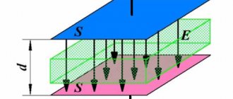
Insulation resistance measurement is carried out in order to protect a person from electric shock and for fire safety purposes. Hence the minimum resistance value is 500 kOhm. It is taken from a simple calculation:
U – phase voltage of the electrical installation;
RIZ – insulation resistance of electrical equipment;
RF is the resistance of the human body; for electrical safety calculations, RF = 1000 Ohm is taken.
Substituting known values (U=220 V, RIZ=500 kOhm), a leakage current of 0.43 mA is obtained. Sensible current threshold is 0.5 mA. Thus, 0.5 MOhm is the minimum insulation resistance at which the average person will not feel any leakage current.
When measuring with a megohmmeter, you should also pay attention to safety, because the device produces up to 2500 V on its probes, it can be fatal to humans. Therefore, only specially trained personnel can carry out measurements. The connection of the megohmmeter and measurements must be carried out at an electrical installation disconnected from the electrical network. It is necessary to check the electrical wiring for lack of voltage. If testing is carried out on a cable, the area should be protected from accidental contact with bare parts of the cable at the opposite end from the test site.
Test standards established by the PUE
For cable lines of different classes and designs, test voltage parameters and the time during which the cables must be exposed to it are established. Before high-voltage tests, as well as upon their completion, the cable insulation resistance must be measured, which is performed with a 2500-volt megohmmeter. Testing the insulation of 0.4 kV cables should give a result of at least 0.5 MΩ; cables of this class are not tested by applying increased voltage.
Checking the insulation resistance of high-voltage cables using a megohmmeter is of an approximate nature, and the resistance value is not standardized. This is explained by the fact that these cables are subjected to high-voltage tests, which provides a more objective assessment of the condition of their insulation.
During high-voltage tests, paper-insulated cables with a rated voltage of 2–10 kV are exposed to a rectified current voltage of 6 times the nominal value. For example, a 6-kilovolt cable is tested at a voltage of 36 kV, a 10-kilovolt cable is tested at 60 kV.
Cable lines 20 - 35 kV are tested at 5 times the nominal voltage. When testing 110 kV cable lines, a voltage of 300 kV is applied to them, and 450 kV to 220 kV cables.
The test duration (that is, the time spent under the influence of increased voltage) established for CLs with paper insulation is 10 minutes.
Licenses and certificates
Due to technical difficulties, for testing cable lines of 110 - 220 kV, instead of increased rectified current voltage, it is allowed to use alternating voltage of industrial frequency. Thus, for lines 110 - 220 kV, tests are carried out with an alternating voltage of 130 kV in relation to the ground, for lines 220 - 500 kV - 288 kV under the same conditions. The duration of the test is 5 minutes.
High-voltage cables with rubber insulation for 3 and 6 kV are tested at double rectified voltage from the nominal voltage for 5 minutes.
Method for measuring cable insulation resistance
First, personnel must determine that there is no voltage on the cable using a voltage indicator. At the opposite end, the cable cores must be separated at a sufficient distance so that there is no accidental short circuit. Then prohibition signs are posted in the testing area. You should also conduct a visual inspection of the cable, if possible, to determine if there are hot spots or exposed areas. After this, you can start measuring. It is necessary to measure the insulation resistance between phases (A-B, A-C, B-C), between phases and zero (A-N. BN, CN), between zero and the ground wire. The time of each measurement is 1 minute. After each test, it is necessary to ground the cable core, although modern megohmmeters can carry out independent discharge. The results obtained are recorded in the protocol. It is worth remembering that if the data obtained is made for some inspection commission, only a specialized electrical laboratory has the right to make the protocol.
Instruments for measurements
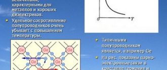
For testing with constant pulsating voltage, the best choice is a megohmmeter. In devices of older designs, a built-in mechanical generator operating on the principle of a dynamo was used to obtain voltages. To produce the required voltage, it was necessary to twist the knob hard. Currently, megohmmeters are made in the form of electronic devices powered by batteries; they have a compact size and convenient software. Modern megohmmeters have a memory where several tests are stored. With each measurement, the absorption coefficient is automatically calculated. Its value is determined by the ratio of the polarization current to the leakage current through the dielectric - the winding insulation. With wet insulation, the absorption coefficient is close to 1. With dry insulation, R60 (insulation resistance 60 seconds after the start of the test) is 30-50% greater than R15 (after 15 seconds).
Measuring instruments
Instruments for measuring insulation resistance are conventionally divided into two groups. These are: panel AC meters and small-sized devices (they are carried manually). The first samples are used in conjunction with mobile or stationary installations that have their own neutral. Structurally, they consist of relay and indicator parts and are capable of continuous operation in existing networks of 220 or 380 Volts.
Most often, measurements of the insulation resistance of electrical wiring are organized and carried out using mobile devices called megohmmeters. Unlike a conventional ohmmeter, this device is intended for measurements of a special class, based on assessing the state of insulation when exposed to high voltage.
Please note: Pulse messages with an amplitude of about 1-2 kV are generated by the megohmmeter itself.
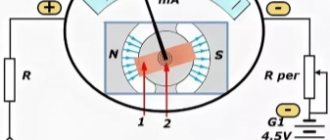
Known models of these devices are analog and digital. In the first of them, a mechanical principle is used to obtain the required value of the test voltage (as in a “dynamo”). Experts often call them “pointer”, which is explained by the presence of a graduated scale and a measuring head with an arrow.
These devices are quite reliable and easy to use, but today they are obsolete. The main inconvenience of working with them is their significant weight and large dimensions. They have been replaced by modern digital meters, the circuit of which includes a powerful generator assembled on a PWM controller and several field-effect transistors.
Such models, depending on the specific design, can operate both from a network adapter and from autonomous power supply (one option is rechargeable batteries). Indications for measuring the insulation of power cables in these devices are displayed on the LCD display. The principle of their operation is based on a comparison of the parameter being tested and the standard, after which the received data enters a special block (analyzer) and is processed there.
Digital instruments are characterized by their relatively light weight and small size, which is very convenient when conducting field tests. Typical representatives of such devices are the popular Fluke 1507 meters (photo on the left). However, to work with an electronic circuit, you need a certain level of qualifications that allows you to prepare the device and obtain a minimum error in measurements. The same approach will be required when handling an imported digital product labeled “1800 in”.
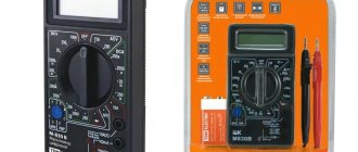
It is important to note that it makes no sense to check the insulation of cable products using conventional measuring instruments. Neither the most “advanced” multimeter, nor any other similar model is suitable for these purposes. With their help, it will be possible to make only an approximate estimate of the parameter obtained with a large percentage of error.
What is a megohmmeter?
A device for measuring the insulation resistance of electrical wiring is called a megohmmeter . Its operating principle is based on measuring leakage currents between two points in an electrical circuit. The higher they are, the lower the insulation resistance, and, accordingly, this electrical installation requires increased attention.
So:
- There are currently two main types of megohmmeters on the market. Devices powered by a generator built into the device, and more modern megaohmmeters with a battery.
The photo shows a universal megohmmeter
- By size, megaohmmeters can be divided into devices with rated voltages of 100V, 500V, 1000V and 2500V. The smallest megohmmeters are used to test electrical installations up to 50V. Depending on the rated loads, for circuits with voltages up to 660V, devices of 500 or 1000V are usually used. For circuits with voltages up to 3 kV - 1000V megohmmeters, and for electrical installations and conductors of higher voltage - 2500V devices.
Who and when has the right to take measurements with a megohmmeter?
Devices for measuring the insulation resistance of electrical wiring have certain requirements for working with them. So, to independently work with a megaohmmeter in electrical installations up to 1000V, you need a third group of electrical safety approval. So:
- The frequency of measuring the insulation resistance of electrical wiring is determined by PTEEP (Rules for the Technical Operation of Consumer Electrical Installations) and for lighting network wiring is once every three years. The same standards apply for electrical wiring of office premises and retail pavilions.
Note! External electrical wiring and wiring in particularly hazardous areas must undergo insulation resistance measurements annually. In addition, the electrical wiring of cranes, elevators, children's and health facilities is checked annually.
- The frequency of checking the insulation resistance of electrical wiring of electric furnaces is once every six months . In this case, measurements should be made during the maximum heated state of the furnace. In addition, once every six months you should visually inspect the condition of the oven’s grounding. The same inspection standards apply to welding machines.
How to work with a megohmmeter?
To connect to the electrical network, the device for measuring the insulation resistance of electrical wiring has two leads up to three meters long. They make it possible to connect the device to an electrical circuit.
Connection diagram for a megohmmeter in a three-phase circuit
Note! To work with a megohmmeter in all electrical installations where measurements are to be taken, the voltage should be removed. In addition, voltage should be removed from adjacent electrical installations that may be accidentally touched.
So:
- Before use, the megohmmeter must be tested for functionality. To do this, first short-circuit the terminals of the device. Then we rotate the generator handle and check the presence of the circuit according to the instrument readings. After this, we isolate the leads from each other and check the maximum possible readings on the device.
- After this, we proceed directly to measurements. To measure a three-wire single-phase circuit, the sequence of operations should be as follows:
- In the lighting network, unscrew all the lamps and disconnect all electrical appliances from the sockets.
- After this, turn on all the lighting switches.
- According to PBEE (Rules for the Safe Operation of Electrical Installations), all work with a megohmmeter must be performed with dielectric gloves. After all, the voltage at the device terminals is at least 500V, so this requirement should not be neglected.
- We connect the leads to the phase and neutral wires of the lighting network. We take measurements. According to PTEEP , it should show a value of at least 0.5 MOhm.
Note! When performing measurements, measures must be taken to prevent damage to semiconductor and microelectronic devices in the circuit. Therefore, if there are any in your circuit, they must be “unhooked” before taking measurements.
- After taking the measurement, the phase wire should be discharged before touching it. In general, the capacity of lighting conductors is not large and this point could be omitted, but if there are large inductive or capacitive resistances in your network, removing the charge from the conductor is necessary, because the cost of not performing this action can be very high. By the way, for the same reason we do not measure the absorption coefficient of insulation.
- Then we make the same measurements in relation to the phase wire and grounding and the neutral wire and grounding. In all cases, readings should be above 0.5 MOhm.
- If it is necessary to measure the insulation resistance of a three-phase circuit, then the sequence of operations is the same. Only the number of measurements is greater, because we need to measure the insulation between all phase conductors, the neutral wire and the ground.
Preparing for measurements
Preparation for conducting insulation tests comes down to choosing a device that is suitable in its characteristics for the stated purposes, as well as organizing the measurement scheme. The following devices are considered the most suitable for most cases:
- Megaohmmeters type M4100, having up to five modifications.
- Meters of the F 4100 series (models F4101, F4102, designed for limits from 100 Volts to one kilovolt).
- Devices ES-0202/1G (limits 100, 250, 500 Volts) and ES0202/2G (0.5, 1.0 and 2.5 kV).
- Digital device Fluke 1507 (limits 50, 100, 250, 500, 1000 Volts).
Megaohmmeter M4100Megaohmmeter-F-4100Megaohmmeter-ES-02021G Digital meter Fluke 1507
Important! For measurements, only pre-verified devices are taken, which must have a manufacturer’s license.
According to the PUE, before measuring insulation resistance, you will need to prepare a diagram for connecting the megohmmeter to the elements of the object being tested. For this purpose, the meter kit includes a pair of flexible wires no more than 2 meters long. Their own insulation resistance cannot be less than 100 MΩ.
We also note that for the convenience of checking the cable insulation with a megohmmeter, the working ends of the wires are marked, and special tips are put on them on the device side. On the return side, the measuring cables are equipped with alligator clips with special probes and insulated handles.
Bottom line
Measuring cable insulation resistance is a responsible procedure, the correct execution of which determines the safety of both people and equipment. Therefore, you should not neglect this simple but useful operation. This will help save a lot of money.
Coffee capsule Nescafe Dolce Gusto Cappuccino, 3 packs of 16 capsules
1305 ₽ More details
Coffee capsules Nescafe Dolce Gusto Cappuccino, 8 servings (16 capsules)
435 ₽ More details
Samsung Galaxy S smartphones