Jumpers in the electrical panel. Which wire to use
Brands and wire sections for assembling an electrical panel.
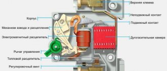
What design features should a conductor have? In the power supply of any facility, from utility rooms, warehouses, to high-tech industries, it is impossible to do without electrical panels. The shield itself contains switching equipment and automation, as well as means for distributing and connecting consumers to the power supply network. In simple terms, the switchboard can be an input distribution device (IDU) or an automation and control panel. For normal operation of the system, it is necessary to use installation wires of appropriate quality in compliance with the conditions for their laying and installation.
Features and installation rules
A typical comb busbar is mounted within the boundaries of the input or distribution panel very simply, without causing any particular difficulties for the contractor. However, there are a number of nuances in this matter, which must be taken into account when installing a comb for circuit breakers.
According to the requirements of regulatory documents, the phase bus is placed only on the upper contacts of machines combined into one line.
Features of connecting the bus to the comb are also manifested in the following subtleties:
- Since its conductive part, during installation, falls between the lower pressure plate and the comb itself, the plastic insulating protrusion on it must face the direction of the screw fastening.
- If this requirement is violated, it is not possible to obtain an aesthetic connection that does not bend the plate.
- When installing a 3-phase type comb, it is important to ensure that the insulators are positioned correctly, which will eliminate the possibility of an interphase short circuit.
When installing connecting busbars for machines instead of standard wire jumpers, it is necessary to comply with generally accepted markings. It is applied to the housings of mounted products and must comply with the requirements of current regulations.
Typically, such combs are sold as already measured standard rulers, the number of mounting contacts on which varies. Therefore, before connecting, the total number of connected machines is calculated and, taking into account their thickness, the unnecessary part of the bus is cut off.
What does an electrical panel consist of?
The input cable is connected to the electrical panel through holes in the housing, then connections are made to the electrical equipment in accordance with the diagram. For example, when assembling a switchboard, the power cable is connected to the input circuit breaker, and the corresponding equipment that belongs to each consumer group is connected to it.
Inside a modern home electrical panel there is a large number of different switching and protective devices and other types of equipment, including:
- metering device (electricity meter).
- automatic switches (input or disconnecting groups and individual consumers);
- RCDs and automatic devices;
- timers;
- voltage relay;
- phase control relay;
- other automation.
The electrical panel body must be grounded, as well as its metal doors and other live parts. To restrict access by unauthorized persons and prevent electric shock, it must be locked with a key.
Design features
First, let's look at the design of the comb. The product consists of a copper plate placed in plastic insulation that does not support combustion. Special leads extend from this plate, thanks to which the machines in the panel are connected. The number of plates corresponds to the number of poles.
Please note that there are combs with pitches of 18 and 27 mm. The first ones are intended for switching AVs with a width equal to one module. Accordingly, 27 mm is a width of 1.5 modules. Pay attention to this point when choosing a distribution bus for your own conditions!
Based on the number of poles, connecting busbars are divided into single-pole, two-pole, three-pole and four-pole. Each design option has its own purpose. For example, a single-pole comb is used to connect a single-phase circuit breaker, and a four-pole comb, respectively, is used to install three-phase RCDs with 4 poles (three phases and zero).
The number of taps can be from 12 to 60, so the use of combs to connect two electrical machines is not a rational solution. It is advisable to use a distribution bus when assembling large panels.
The taps themselves can be pin (marked pin) or fork (fork). The former are used much more often, because Fork outlets are not suitable for all machines; they require a special clamp.
The last design feature that I would like to talk about is the cross-section of the bends. As a rule, taps are made with a cross-section of 16 mm2, which is quite enough to withstand a current load of 63 A.
What should the wire be like?
The requirements for cable products of any type are determined from the conditions in which they are used and laid. In an electrical panel, due to the limited space during its assembly, there is a need for compact routing of wires. Therefore, during assembly, the wire for the electrical panel is bent in accordance with the diagram to connect the functional elements. This implies that the wire must withstand bending normally, so aluminum conductors are poorly suited for this purpose - they break after several bends. Therefore, preference should be given to copper conductors.
Wires are distinguished by flexibility class, which depends on the design of the cores - monolithic (single-wire) and multi-wire. Solid cores, although difficult to bend, can be directly connected to terminals and screw terminals. In addition, flexibility after installation in the electrical panel is not required.
It is more convenient to work with a flexible stranded conductor during assembly, but there is a significant problem - it cannot be used to connect to terminals and screw terminals, which are used in all automatic machines and other equipment. To connect a flexible wire to such a terminal, you need to either tin the end or crimp it with a tip like NShVI or NShVI2 and the like. If you neglect this, the contact will be unreliable and short-lived.
Taking into account all of the above, we can conclude that domestic wires are suitable for installation in an electrical panel:
PV-1 (PuV) – single-wire copper core, single PVC insulation, flexibility class 1.
PV-3 (PuGV) – stranded copper core, PVC insulation, class 2 flexibility - 0.5 to 1.5 mm2; flexibility class 4 – from 2.5 to 4 mm2; Flexibility class 3 – sections exceeding 4 mm2.
PV-4 - stranded copper core, PVC insulation, more flexible than the previous one, depending on the cross-section, PV-4 has 4 or 5 flexibility class.
Design
The combs have a prefabricated design. The structure is based on a flat copper busbar. It has bends for installation on machines. Depending on the number of connected phases, there are 1 or 4 buses in one comb. They are insulated with non-flammable plastic. Usually white or gray.
The design is made in such a way that when assembled there are practically no exposed conductive parts. This increases the safety of operating personnel. And the junction box becomes less susceptible to dust.
How to select a wire cross-section for connecting machines in a panel
The electrical panel contains switching components and automatic devices, as well as equipment for connecting and distributing consumers over the network. To optimally perform your duties, you need to choose the right installation wires and lay them correctly. Selecting the right conductors and making the correct connections will increase the safety of the electrical wiring and ensure its long-term operation.
- The composition of the electrical panel and its design
- Wire selection
- Required Tools
- Installation and connection
- Preparation of jumpers and connection diagram
- Basic rules for laying wires
Schemes for connecting machines through a connecting comb
The comb bus for automatic machines is inserted into the connecting chain according to certain rules specified by the electrical circuit for its connection.
Since the connection of machines in 220 Volt networks is carried out only in phase (without zero), such a bus is usually called phase.
Depending on the type of power circuit into which the jumpers for the machines are included, they are designed to operate either in a single-phase line (220 Volts) or in a three-phase network. In the second case, the switching circuit is a triple copy of a single switching. The difference between the two options appears only in the design of the bus connector itself.
According to the PUE, the element is designed to create reliable contact between the upper (supply) terminals of automatic devices, the voltage from the output of which is supplied to the load line. To do this, the busbar must withstand significant currents, which determines the scheme for its inclusion in the general power circuits - all machines are connected with its help in parallel at the input. This rule is true for both single-phase (single-row) buses and three-phase combs for automatic machines. In the second case, the copper product has three insulated rows, offset by a step, corresponding to the distance between the phase terminals of a 380-volt switching device.
The composition of the electrical panel and its design
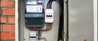
Composition of an electrical distribution panel in an apartment
The electrical panel is a metal box containing various switching and protective devices. They are connected using wires that have special requirements.
An input cable is inserted into the electrical panel through a special hole. After this, the electrical equipment is connected and the wires are laid inside the panel. The conductors must be connected according to the developed diagram.
A modern home panel includes the following switching and protective devices, as well as other types of products:
- Electricity meter.
- Automatic machines. They are installed at the entrance and to individual groups of energy consumers. Typically, an automatic switch is selected for the entrance, for the lighting group and for powerful electrical equipment in the apartment.
- RCD.
- Diffautomatic machines.
- Timer.
- Voltage and phase control relay.
- Other automation for control and monitoring.
The housing must be grounded, as well as metal doors and live parts. Otherwise, if there is a current leak, the shield will pose a potential danger to human life and health. The shield should be locked with a key to prevent access by unauthorized persons and to prevent electric shock.
What is important to know?
Depending on the number of phases at the input, there are:
- single-phase network;
- three-phase network.
By installation method:
- by means of a splint (comb);
- jumpers made of stranded wire;
- jumpers made of single-core wire.
Based on the initial data, it is necessary to select electrical fittings and install circuit breakers in the panel, choosing from those listed the desired connection method for your electrical network.
Installation work for single-phase and three-phase circuits differs slightly. In a single-phase network, all circuit breakers are supplied with one phase at the input and the circuit breakers use single phases. For a three-phase network, I use triple circuit breakers in the case of connecting a three-phase load, or you can install single circuit breakers for each phase separately, in the case of a single-phase load.
Required Tools
To reliably make a connection in the panel, you need to purchase special tools in advance. They must be professional and have insulated handles. Required tools include:
- Hammer.
- Bulgarian.
- Screwdrivers, including an indicator screwdriver for checking the absence of voltage on the wires.
- Knife.
- Device for stripping insulation.
- Pliers.
- Wire cutters.
- Portable lamp.
After preparing the tool, you can begin installation.
Connecting bus for a machine (comb) - how to connect
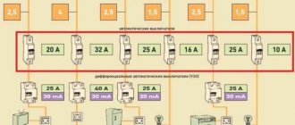
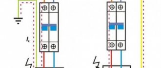
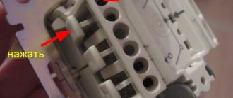
There are several accessories available to make switchboard assembly easier. For example, to connect a group of machines in parallel, it is necessary to make several jumpers from an insulated solid wire of the appropriate cross-section (see Fig. 1). This option has a significant drawback - when one jumper is damaged (for example, it burns out due to poor contact), subsequent circuit breakers will be de-energized. If a 1-phase or 3-phase connecting bus is used for the machine, the described situation is completely excluded.
Let's consider how this device works, the feasibility of its use, advantages and disadvantages. At the end of the article, the installation will be briefly described.
Figure 1. Example of using jumpers (highlighted in red)
Design features
Figure 2 shows a disassembled single-phase legrand comb bus for 12 modules. As you can see, the design of this device is quite simple; it includes a copper bus “a” and its insulator “b”. Everything is simple and convenient.
Figure 2. a) Comb phase busbar with taps; b) insulator
An example of using such a comb is shown in Figure 3.
Figure 3. Example of connecting Schneider Electric AVs installed on a DIN rail (single-row power bus is marked in red)
Depending on the purpose, the connecting comb can be manufactured in a single-pole, two-pole or four-pole design. The first ones are used for ordinary AVs, the second ones when connecting single-phase RCDs, the last ones for three-phase ones. Figure 4 clearly demonstrates examples of the use of buses with different numbers of poles.
Figure 4. Options for using one-, three- and four-pole connectors
Explanation of the picture:
- A - two-pole circuit breakers are connected using two single-pole connectors (zero bus and phase);
- B – connection of devices of the same type when a three-phase electrical power supply is used. Single-pole and three-pole contact jumper are used;
- C – use of a four-pole jumper (common zero and three phases) for automatic circuit breakers or three-phase RCDs.
Note that two-pole combs are also produced; the principle of their connection is the same as in option “A” in Figure 4.
Features you need to pay attention to.
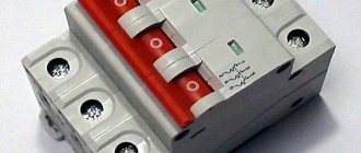
The shape of the taps can be of the pin type (this design is shown in Figure 2) and “fork” (see Figure 5). The first option is more common because it can be used with various types of devices.
Figure 5. Fragment of a three-pole comb with “fork” taps
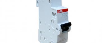
As for the “fork” taps, their connection to the module is possible if it has an appropriate clamp, for example, like the two-terminal switch of the ABB S200 series, shown in Figure 6.
Installation and connection
Accepted colors of phase, neutral and ground wire
Before starting work, it is necessary to de-energize the room. Using a tester, it is checked whether voltage remains on the conductors. Using the probes of a screwdriver, you need to touch each core one by one. If the light does not light up, you can start working. It is prohibited to work with electricity turned on. It is also important to prepare tools in advance and provide the master with an autonomous light source.
When connecting wires in a panel, it is important to remember that the colors of the wires indicate their purpose. The core can be completely painted in one color or another or have a color mark at the entrance to the device, that is, at the ends of the conductor. The following scale is used:
- Phase – gray, black.
- Zero is blue.
- Grounding – yellow-green.
Connecting three-phase circuit breakers and RCDs
With three-phase protection devices you will need a 3 or 4 pole comb busbar. A four-pole comb is necessary when, in addition to 3 phases, a neutral wire is also used.
Assembling the chain is carried out similarly to the previous method. The bus is located on top of the RCD or differential circuit breaker. The comb to which the L1 wire is connected must supply voltage to all L1 terminals of the protective devices. For L2, L3 and N - the same. In this case, L1, L2, L3 and N should not be connected to each other. After installation, it is necessary to turn off all machines and make sure that there is no such short circuit.
Preparation of jumpers and connection diagram
Making a jumper in a non-breaking way
Conductors need to be prepared for connection in the panel. To do this, you need to strip the ends from the insulation using a knife or a special tool. The cores should be inserted into contact and tightened well with a screwdriver.
During operation, you need to pay attention to the following:
- The insulation should not get caught in the clamp.
- The exposed part of the wire should not stick out from the contact over a large area. This requirement is made by network organizations that seal meters. This helps prevent illegal connections from outsiders.
- The upper screw is tightened first, followed by the lower one.
The last step is to check the reliability of the fixation. The veins need to be carefully touched and pulled apart. The conductor should not swing or stagger.
Connection of machines
Next you need to connect the neutral wire. It is connected using a jumper from the lower right contact of the automatic two-pole switch to the third contact of the electric meter. The ends also need to be stripped of insulation, connected and tightened with screws. The wires must not touch each other. Be sure to leave a gap between them.
Now you need to connect the outgoing wires from the meter. First, the phase is connected through a jumper to the upper contact of the machine. The ends are stripped and joined. The phase also needs to be distributed among other sources in the directions of the machines.
There should be one contact left from the electricity meter in the apartment. This is the outgoing zero contact, which must connect to the zero bus. Usually it comes complete with a plastic box. Length, dimensions and configuration vary by manufacturer.
Advantages and disadvantages
The advantages of using copper-based connecting combs include:
- Simplicity and high speed of assembly.
- Obtaining a high-quality and reliable electrical connection.
- Reducing the total number of contacts by half, which increases the reliability of the connections formed.
When installing standard jumpers made from electrical wires, there are two exposed contact ends per clamp. When using a single-phase comb, for example, only one tooth (bend) is used.
Installation specialists solve the problem of saving contacts in their own way - they connect the machines not with separate jumpers, but with a continuous wire. To do this, loops with the required bending radius are made in the electrical connection areas.
The disadvantages of the connection method, which uses electrical connecting buses, include:
- It is inconvenient to replace the automatic protection device, since in this case you have to remove the entire comb.
- Impossibility of adding another machine (this will require a new dimension).
One of the possible solutions to the problem of the second case is to install backup devices with frequently used ratings of 10 and 16 Amps in the panel in advance. Their output contacts are left unused until a certain point in time, and they themselves constantly remain in the off state.
Taking into account the special techniques for installing machines and their redundancy, the use of connecting combs is advisable in any situation, despite the existing disadvantages.
Basic rules for laying wires
All wiring connections in the electrical panel must be insulated.
All of the above actions must be performed in accordance with the rules adopted by the PUE. Failure to comply may result in negative consequences, including electric shock and possible short circuit.
- The input panel, distribution boxes, and meter must be mounted in easily accessible places.
- The wires should not intersect; there must be a distance between them.
- The cross-section of the wire in the panel for connecting automatic devices, RCDs and other products is selected depending on their current load.
- A conductor layout plan should be created.
- Wires should not touch metal parts and building elements.
- All connections in the junction box must be securely insulated.
- Protective and neutral wires are attached to the devices using a bolted connection.
While working, be sure to follow safety precautions. The technician must wear protective dielectric gloves and goggles.
Source
Connection methods
Comb
For convenient and high-quality connection of circuit breakers in the panel, you can use a bus. Depending on the number of phases, you can select the desired comb:
- for a single-phase circuit - single-pole or double-pole;
- for three-phase - three- or four-pole.
Installation is very simple. For the required number of circuit breakers, a comb with a certain number of poles is selected. If the comb has a larger number of contacts, remove the excess (you can use a hacksaw). When completing installation, insert the busbar simultaneously into all terminals of the machines and tighten the screws. The outputs are mounted according to the diagram. We talked in more detail about how to connect circuit breakers with a comb in the corresponding article. The video below clearly demonstrates the connection technology: