Purpose and scope of application
This type of device allows you to switch two or three (if a three-key design is used) groups of devices (lighting sources, hood, etc.) or turn on/off individual groups.
Using a two-key design, it is easy to control the intensity of room lighting. For example, if you are using a three-bulb light source, you can connect it to create two groups. Then you can turn on one, two or all light bulbs at once. How to implement this option will be described below.
This is what double and triple switches look like
The second, no less common option is to control the lighting of a separate bathroom.
Of course, you can use two single structures for these purposes, but installing a double one provides the following advantages:
- when installing hidden structures, you will only need to make one seat;
- the cost of a one-key and two-key switch is approximately the same, but two of the former are needed;
- two devices look less aesthetically pleasing than one and take up more space, which can be critical in some situations.
Practice
In practice, to make a switch you will need, for control from two places, two single-key switches and two two-key switches of the same company and one series. One series is needed to match the key sizes.
- Next, we take the two-key switches and disassemble them, removing the keys;
- The general task is to turn one contact group 180 degrees and install one common key instead of two;
- Not every switch will allow itself to be damaged, so for these homemade products you need to choose the simplest switch models possible.
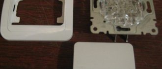
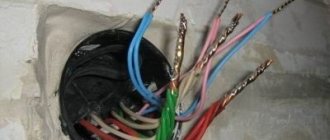
Note: most often you have to be creative in making a pass-through switch for open wiring. Pass-through switches for open wiring are difficult to find. The photo shows a pass-through switch for hidden wiring.
After rotating the contact group 180 degrees, all that remains is to assemble the switches and install one instead of two keys.
- Next, the resulting two pass-through switches are mounted according to the diagram in the place where it is necessary to control the lighting from two places.
For example, in the bedroom, placing one switch at the entrance, and the second at the bed. Or in the house, placing one switch in the hall and the second on the second floor. Or in a long office corridor, placing switches at different ends of the corridor. Here's a good example, albeit without a corridor:
Related articles: Automation and control panels
lighting control from two places
lighting from three places
Design Features
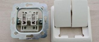
Two-key devices for turning on/off the load are structurally almost identical to single-key devices, the main difference lies in the switching mechanism. Below, Figure 2 shows the main design elements.
Figure 2. Main design elements
Designations in the photo:
- A – keys;
- B – external panel-casing;
- C – internal panel;
- D – switching mechanism;
- 1 – input;
- 2 and 3 – contacts for control wires going to the chandelier.
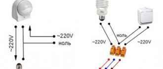
Now let's look at how the contact group diagram of the switching mechanism is arranged; it is shown in Figure 3.
Drawing. 3. Contact diagram of a two-key device
As can be seen from the presented diagram, the switching mechanism has three contacts, “1” is a common input, “2” and “3” are two control outputs.
Now that we have figured out the design of two-key switches, we can move on to their connection diagram.
What is the difference?
The functional difference between a conventional light switch and a walk-through switch is the lighting control capabilities. A simple switch, after pressing a key (or keys), opens or closes the phase circuit going to the lighting device. The pass-through switch not only opens (or closes) the phase circuit, but also simultaneously closes (or opens) the second phase circuit, connecting the second pass-through switch of the circuit to operation.
It is important to understand the terminology. A pass-through switch is often called a switch. It has three contacts and is used to control lighting from two places, as well as from three places, occupying extreme positions 1 and 3.
There are also pass-through switches (crossover switches or double pass-through switches) that have six contacts and are used to control lighting from three locations at location 2, between switch positions 1 and 3.
The design difference between a simple switch and a pass-through switch (switch) is in the number of contacts for connection. A simple single-key switch has two of them. In a simple two-key switch there are four of them by design, but two of them are closed. There should be three of them in the pass-through switch, but there is only one key.
key switch diagrams
As we can see, according to theory, the two-key switch is structurally closest to a pass-through switch. Three contacts work here and there, and this will help us make a switch out of a switch.
Related articles: Selection and installation of lamps in a suspended ceiling
How to connect two-key switches
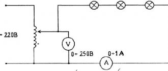
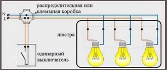
Let's consider the connection using the example of a two-section lighting fixture (the diagram is shown in Figure 4). Note that this is a standard option that is used to turn on/off any devices.
Drawing. 4. Connecting a two-section chandelier to a double switch
As can be seen from the figure, the zero is supplied directly to the lighting sources, in contrast to the phase, which is switched. When the “cl1” contact is triggered, “L1” is turned on, respectively, “cl2” is responsible for the operation of “L2” and “L3”. As a result, we can set three options for the intensity of lighting in the room (one, two or all light bulbs are on).
Please note that the phase is supplied to input “1”, and two control lines are supplied to the outputs (“2” to “L1” and “3” to the group “L2” and “L3”). The supply can be made with a three-wire cable; if this is not available, then 3 wires are laid.
The option shown in Figure 4 is more general. Therefore, I will also give a simpler connection diagram specifically for 2 light bulbs (lamp):
Simple connection diagram
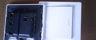
Switch device with two keys
In terms of external features, such a switch is very similar to a conventional device, the only difference is in the design of the internal mechanism. The case consists of a frame and keys.
A switch with two keys allows you to control the lighting of two groups and consists of:
- frame;
- two buttons for switching;
- input and output terminal blocks.
Terminals and screws can be used as fasteners. Electric current is supplied to the first terminal. After this, 2 wires are connected to the mechanism, which control the interaction of the key devices. A cable harness is connected to the clamps, which connects the switch to the lighting devices. It is believed that a two-key switch is a modification of a single-key device.
Often there are modular switches that consist of 2 single connecting parts.
The principle of operation of a double switch is the interaction of contacts and wires that are connected to lamps of various designs.
Connection of cables and wires occurs thanks to terminal blocks. Terminals are special devices that are equipped with self-clamping mechanisms. Terminal clamps have recently become very popular because to make a connection you just need to clear the ends of the wires of the insulating material and connect them to the terminal.
There are switches with screw terminals; everything happens in them in a similar way, only the fixation occurs by tightening the screws.
Important! Experts recommend using a double switch with terminal blocks. This connection is considered durable and easy to install. Screw terminals loosen contact over time, which leads to a disruption in the flow of electrical current.
There are types of modern two-key switches that are equipped with a backlight and an indicator. The backlight helps to detect the device in the dark, and the indicator shows the presence of a closed circuit in the lamp.
Advantages of double switches
Devices with two keys have the following advantages:
- one device can control the operation of several lamps or lighting fixtures;
- ensuring control over the intensity and brightness of light in the premises. A single switch, when pressed once, turns on all the light bulbs of the lighting fixture, but a double switch can be used not at full strength by turning on one key;
- the ability to adjust lighting in two rooms at once;
- economical consumption of electricity;
- rational use of cables and wires;
- It is allowed to turn on one lamp, which has a beneficial effect on eye health. Everyone knows the feeling when all light bulbs are connected at once; this happens with a single switch;
- convenience when connecting two-key switches for damp rooms or street lighting, since one device is much more convenient to camouflage from bad weather or shocks. When installed outdoors, switches must be protected with special covers.
Important! To create uniform lighting, it is possible to use a dimmer, which allows you to adjust the light.
How to make a switch from a switch
Let's look at the connection diagram for a two-key switch. The switch has contacts 1-2-3-4. In fact, contacts 1 and 3 are closed, the phase comes to them. The phase going to lighting is removed from contacts 2 and 4. Closing/opening of contacts 1-3 and 2-4 independently, which allows you to independently control lamps A and B.
To make a switch from a switch, contacts 1-2 and 3-4 need to operate in opposite modes, that is, when contacts 1-2 are closed, 3-4 must be open and vice versa. Moreover, switching should be done with one key.
Methods of application
The large number of advantages of such a device allows it to be used in almost all rooms of a house, apartment, office, etc. In addition, a two-key switch can serve as a regulator for the operation of lamps in several rooms at once, for example, a bathroom and toilet or a corridor and a kitchen. In order to carry out installation correctly, you need to know how to connect a double switch to two light bulbs.
Important! Devices that control lighting in two rooms at once are most often installed outside the room. This requirement is specified in the PUE (electrical installation rules).
Thus, we can conclude that the scope of use of two-key switches is huge.
Drawing up a drawing for connection
Before carrying out installation work, a connection diagram is required. The drawing must clearly show the routing of the wire. Basically, a phase wire is connected to the switch. The ground and neutral wires are connected directly to the lamp. There are 2 cable wires coming from the switch, each of which must be connected to light bulbs or other lighting devices.
The basic principle of the diagram is to indicate the connection of wires from the junction box to the lamp.
Materials required for connection
After drawing up the diagram, they begin to prepare the materials necessary for installation. The list of additional materials includes:
- electrical wires, the cross-section of which must be at least one and a half square millimeters. To accurately determine the footage, you should measure the room using a tape measure;
- two-key switches;
- insulating tape;
- mounting box;
- terminal blocks or screw terminals.
- Phillips and flat screwdrivers;
- assembly knife for removing insulating material;
- side cutters;
- level;
- pliers;
- hammer and chisel in case of need for the process of scoring or deepening for socket boxes.
Installation of electrical wires
Before making the connection, you need to check the wires used. To do this, it is necessary to test and determine which of the wires is phase. For testing, an indicator screwdriver is used, which will indicate the presence of current with an LED signal. It is necessary to mark the phase wire so as not to later confuse it with the neutral wire.
Before installing a double switch, you should correctly lay out the electrical wiring to the location of the device. In cases where a hidden wiring method is used, the wiring is carried out before the walls are plastered. Only after this are switches and lamps installed in place, and then connected. The wiring is carried out according to a pre-drawn diagram.
When using the open method, the wiring is laid in cable ducts or corrugated pipes. In cases of replacing electrical wiring, the hidden method is considered more labor-intensive, since you first need to dismantle the old wiring and then install a new one. The open wiring method is more economical and does not require cost or labor. It's fairly easy to remove the old wiring and connect the new one.
Preparatory stage of connection
After the cable is placed in the designated place, the process of connecting the switches begins. During installation and connection, it is necessary to de-energize the room in which the work will take place.
Important! To turn off the current, just turn off the automatic switch located at the beginning of the branch.
In a well-designed distribution panel, all circuit breakers are marked, and therefore de-energizing the required circuit breaker will not be difficult. If the wires are not labeled, then the machine can be detected by selection.
After wiring the wires, the installation of the two-key switch begins.
The work begins with stripping the ends of the wires. You can connect a double light switch using 3 wires: the first is input, which provides the input of current, and 2 outputs, which are connected to lighting devices. The ends of the wires are stripped of insulation; the stripping distance is approximately 10 cm.
Then the cleaned wires are connected to the terminals. This fastener is designated in the system by the letter “L”. Such a clamp is located on one side of the structure, that is, separately, and cannot be confused. This method is used for two-key switches if their design is not modular.
For modular switches, the connection occurs differently. In this case, the input cable is connected to the terminal of the first module. This terminal is also designated by the letter “L”, only it is connected by a thin wire to the second module. This is how the connection to the phase wire occurs. The output terminals are indicated in the diagram in the form of arrows, and the wiring to them is connected in the same way.
There are several options for connecting a double switch:
- The simplest method is characterized by an equal number of wires from the ceiling and the lighting fixture. To connect such wires, simply twist them together.
- If there are 3 wires on the ceiling, and the chandelier has a larger number of shades, then in this case the wires are distributed into sections and connected to the phase wire.
- If 4 wires come out of the ceiling, in these cases the wires are twisted together. One of the four wires is grounding; it can be identified by its light green color and the “PE” marking.
There are 2 screws on the sides of the structure, with which you can adjust the fixation of the legs. If the device is loose, you can use screws to tighten it and secure it more firmly. To do this you will need a shaped screwdriver.
The box is mounted in a specially prepared recess, after which the upper decorative frame is installed. Then the switch is mounted in the socket box. Bolts or clamps are used for fastening. This process depends on the design of the switch you purchased. There are varieties that have removable frames and push buttons. These elements are removed before connection and installed after completing the entire scope of work.
How to connect a pass-through device
The current is supplied through a distribution box. Select a suitable location, install it and remove the three-core cable. In addition to phase and neutral, it is equipped with a grounding wire, which makes the system safe. Factory color coding of the cores simplifies installation. More often it is a copper flexible cable, the cross-section of individual wires is from 1 to 1.5 mm.
Preliminary markings are made where the switches and lamps will be located. Then the walls are tapped and the conductor lines are laid out. Drill niches for mounting the switch mechanism. After the preparatory work, you can connect the entire system.
For a correct and safe connection, the following sequence must be observed:
Then you can apply current for several hours and check the operation of the system. Each switch must turn the lighting device off and on independently of the other. If this does not happen, you should check the correctness of the diagram. Detected pockets of heat are a sign of poor contact. It is necessary to de-energize the system and reconsider the connection.
Do not twist copper or aluminum conductors.
Tools and materials for connecting a chandelier
Let's determine that you have everything ready to install and connect the chandelier and switch:
- you have a chandelier with 2 – 6 lamps;
- a 3- or 4-wire wire hangs from the ceiling;
- to connect the switch, a two or three-wire wire is laid along the wall.
Let's prepare a tool for this job:
- screwdrivers;
- marker or pencil;
- pliers;
- screwdriver;
- screwdriver indicator (from 90 to 500 V);
- stationery knife;
- hammer drill
You also need to prepare the following material:
- plastic dowel for concrete;
- self-tapping screws;
- WAGO clamps.
Before connecting the lighting fixture, the plate must be screwed to the ceiling. If the lamp must be put on a hook, then in this case we will need the hook itself.
It's very easy with a crochet hook. You just need to insert this hook into the hole and secure it with a nut. Then hang the chandelier.
Before connecting the wires on the ceiling to the chandelier, you need to determine their purpose. Which of them are phase, which wire is the common “neutral”, and which protective conductor is the “grounding”.
Attention! I would like to draw your attention to the fact that according to the rules of the PUE, wires or cables with an additional protective “grounding” wire must be laid on lamps.
Therefore, it is assumed that for chandeliers with separate switching of lamps, using 2-key switches, lay a 4-core cable, and with the simultaneous switching on of all lamps, a 3-wire cable.
To do this, we check that the circuit breaker is turned off and voltage is not supplied to the wire being tested.
Next, remove the insulation from the wires:
After removing the insulation, turn on the circuit breaker again, thereby applying voltage to the wire being tested.
Don't forget that the one-key or two-key switch must be turned on.
Using a screwdriver indicator (capacitive indicator), we check for voltage on all wires.
Of the three wires, two should have voltage. These are phase wires. Such wires are marked with the letter “L”.
This means that the wire on which there is no voltage is the common “zero”. Marked with the letter "N".
Grounding is marked “PE”.
If the electrical wiring in your house (apartment) is made according to all electrical installation rules, then the neutral wire should be blue.
But you should always check with an indicator, because electricians can connect the neutral wire of a different color.
Instructions for replacing the light switch
Before replacing a new light switch in an apartment, you need to dismantle the old keypad and make sure the wiring is in good condition.
How to remove the old switch?
Dismantling the old switch is carried out in accordance with the step-by-step instructions:
- Remove the key and top cover.
- Disconnect the wires using a screwdriver, unscrewing the bolts on the terminals.
- Apply power to the distribution panel and locate the phase wire using the indicator.
- Turn off the mains voltage.
- Mark the phase with insulating tape or another method.
- Loosen the screws holding the spacer tabs.
- Remove the device from the socket.
Scheme for dismantling the old switch
In some cases, the sequence will be reversed - the wires can be disconnected only after the switch is removed. This depends on the design features of the device.
Dismantling the external switch is carried out in a similar manner. The only difference is that instead of loosening the screws of the spacer legs, the screws that secure the device to the wall are unscrewed.
Video instructions for dismantling the old switch can be viewed on the channel “Guys from Stone. Do-it-yourself apartment renovation.”
We are preparing for connection
Before connecting a new device, you must complete the following preparations:
- Loosen the screw terminals so that the wires fit easily into the hole.
- Unscrew the screws of the spacer tabs so that the switch fits freely into the socket box (this operation is not required for outdoor devices).
- Strip the wires when replacing them (if the condition of the old electrical cable is good, there is no need to strip it).
Diagram and connection with one button
After everything is prepared, you can install a breaker with one key, following the detailed algorithm:
- Examine the markings on the terminals of the single-key switch. The phase wire must be connected to contact L, the second end of the cable to connector 1, respectively.
- Insert the bare wires into the contact holes and tighten the terminal screws. Do not apply too much force, otherwise you may break the thread.
- Install the switch in the socket box strictly horizontally without distortion.
- Secure the device with the sliding tabs by tightening the screws.
- Check the correct operation of the lighting fixtures by turning on the circuit breaker on the electrical panel.
- If the switch operates correctly, install the cover and keys.
Diagram and connection with two buttons
Algorithm for installing a switch with two keys:
- Connect the phase wire to contact L, the remaining two ends to connectors 1 and 2 in accordance with the markings.
- Tighten the fastening screws (this operation is not necessary on spring terminals).
- Place the switch in the socket box.
- Tighten the screws of the sliding legs, eliminating even minimal gaps.
- Make sure that the device works correctly by turning on power.
- Install the cover and both keys.
Step-by-step instructions for installing a two-key switch are given in the photo gallery:
Non-standard situation
There are often cases when the wire inside the socket box is too short. It is not long enough to connect a new switch. Such unusual situations arise in old houses, where electrical appliances have already been replaced several times, and the wiring has become unusable. In this case, the cable must be extended.
This will require additional tools and consumables, namely:
- hammer;
- chisel;
- putty knife;
- two-core wire 10–15 cm long;
- a little putty or plaster;
- insulating tape.
Only wires of the same types can be spliced together. A copper cable cannot be connected to an aluminum one - this can lead to oxidation in the contact area, decreased conductivity and burnout of the wiring.
Cable extension is performed in the following sequence:
- Determine in which direction the cable is laid in the wall.
- Carefully release a piece of wire about 10 cm long using a hammer and chisel.
- Cut off the damaged cable section with pliers.
- Strip the ends of the new and old cable, completely removing the insulation in a section of at least 2 cm.
- Tightly twist the protected wires together.
- Wrap the exposed areas tightly with insulating tape.
- Place the connected cable into the channel.
- Cover the damaged area with plaster or putty.
After the solution has completely hardened (after 15–20 minutes), you can continue to install the new switch.
Connecting a chandelier with 3 wires to a two-key (double) switch
Now let's work on the chandelier.
For example, let's take a 5-lamp chandelier. You take the one you have. I repeat. There is no connection difference. The only difference is the number of wires.
The ceiling light uses 2 wires of different colors for each bulb.
Remove insulation from all wires no longer than 2 cm.
Since there are 5 light bulbs in the chandelier, we will divide them into two parts. One has 3, and the other has 2 light bulbs.
Connect all the wires of the 3 selected light bulbs of the same color together. Do the same with two light bulbs. You have 2 twists of phase wires.
Then you need to take all 5 remaining wires of a different color and twist them together. You have made the third general twist of the neutral wires.
Connection diagram for a chandelier to a double switch:
You will get 3 twists. There are also 3 wires on the ceiling.
If you need to connect wires, then for ease of installation I recommend using these “WAGO” connectors:
The convenience is that when you stand on a ladder, you don’t need to turn the screws with a screwdriver in the terminal block. Simply lower the lever and the wire will be fixed. Just make sure that the wire insulation is hidden deeper.
For stranded wires, professional electricians use lugs or a soldering iron, but in our case, lugs are perfect. To crimp them, it is advisable to use a special tool “pliers”.
But if not, you can press it with pliers.
You can, of course, not use the “WAGO” terminal block, but use ordinary twisting and wrap it with electrical tape, but “WAGO” is more relevant today.
So. We connect the “WAGO” terminal block to the chandelier wires. To avoid confusion, it is best to connect the neutral wires to the middle terminal, and the phase wires along the edges.
When everything is ready, connect the wires coming from the ceiling to the chandelier through the WAGO terminal block, knowing in advance where to connect the neutral wire and where the phase wires.
Attach the chandelier to the ceiling by carefully placing all the wires in the decorative glass of the chandelier.
Communities › DIY › Blog › Connecting a double pass-through switch.
I wrote an entry on my personal blog, I think it won’t hurt here either.
I have a problem with this seemingly simple matter. It would seem, what could be simpler? Especially if Google hasn't banned you. There are many good articles on this subject. I used one of them when laying the wires. This one: Connecting a pass-through switch Well, or its clone, it doesn’t matter. The main thing is that I used this diagram: For me it looks like 3 two-core wires suitable for each switch, which I called (signed) “jumper 1”, “jumper 2” and “light corridor 1 (and 2 in second switch)".
Repairs take me a long time, so after a couple of years I bought two El-bi switches, who knows what they are, but there is an ABB brand inside)))) There were no proper terminal markings on the switches. So I just connected everything as in the diagram above. The result was that the machine was knocked out and one of the switches was stuck. Those. not at all what I would like... Well, at least I was convinced that the machines were working. In general, at that time I abandoned this matter until I bought a new switch. Bought. And, lo and behold! The switch (new) has this sticker on the corner of the case:
Well, you have to! The diagram has been attached! But what do I see? I see that the connection diagram for these switches clearly does not match the one I used to connect everything. I start googling further. I find this article: Connection diagram for a two-key pass-through switch
Yes, the switches are almost the same as mine. I label mine for clarity:
Well, it seems like it should be connected according to this diagram:
But the trouble is that according to this scheme, I need to supply a phase to one switch with contacts 1 and 2 (middle), and from the second switch I need to take it from contacts 1 and 2, respectively, and put it on the light bulbs. And I have a phase and a “fence” for one of the light bulbs near each switch. Rewiring is problematic for me. In general, after much brainstorming, I came up with this connection diagram:
Those. The point is that in one switch I supply phase to contact 1 (we are talking about the middle contacts), and I take it from the same 1st contact to the second switch. And for the second light bulb, I apply the phase to contact 2 of the second switch and take it from the 2nd contact in the first switch. I hope that it will be clear to anyone who encounters a similar problem.
PS I made the recording more for myself, so as not to forget. But I will be glad if it helps someone solve the problem.
Comments 86
Good afternoon, tell me if you know. I need a 3-key switch. and one single-key pass-through I want to turn on the head light in 2 places in the room. But for the one with a 3-keyboard, I also want to power the street lighting and the light in the cafe - do you think this is possible?
Unfortunately, I can’t say anything) Theoretically, it’s possible, but you need to twirl the three-keyboard in your hands. Of course, it’s much easier to get by with one pass-through and one regular two-keyboard. But, I repeat, you need to turn the three-keyboard in your hands)) Ask around in stores, maybe there are 2+1 options, like two regular sections and one walk-through, I fully admit that this could happen.
What did you change in your scheme? The usual 2-key switch circuit. And don't confuse a switch with a SWITCH.
operation of switches in short circuit mode
On the switch itself, the consequence is that it will quickly fail due to burning of the contact groups (well, this is not exactly a short circuit, but L meets N)
Either you misunderstood the diagram, or I misunderstood you. Zero and phase do not occur anywhere, well, except for light bulbs)))
Thanks for the tip, that’s what I need to do)
I mean, Gulg didn’t ban you?
switch, not switch)
I wouldn't be so categorical)))
how much did you spend on this matter? Wouldn't it be easier to install a Wi-Fi switch?
Approximately 300 rubles. And what should I do with the Wi-Fi switch then?
these are the same switches, but without wires, but about 300 rubles you were lying, for this money you can’t even buy one standard switch, not to mention a pair, 10-15 meters of wires and gating of walls
I wrote the cost of switches - 45 UAH. for 1 piece
these are the same switches, but without wires, but about 300 rubles you were lying, for this money you can’t even buy one standard switch, not to mention a pair, 10-15 meters of wires and gating of walls
Well, gating the walls against the background of this ha.d-cd.net/677fa74s-960.jpg You understand, it’s not a problem...
I'm not arguing, there are simply more concise solutions for the same money
Yes there is, of course))) And I don’t argue. It’s just that the wires for all this were laid a couple of years ago. And they didn’t particularly look towards “high technologies”... And, to be honest, even now I would not use complex (smart) solutions for simple purposes. The same motion sensors sometimes kill with their incorrect operation, but I don’t even want to think about something more “smart”)))
You can just do this with two switches, what kind of extra splitters are these?))
How to correctly connect a chandelier with 2 or 3 wires to a single-key (single) switch
The process of connecting a chandelier according to the scheme with a single-key switch is the same as with a two-key switch, as described above, only a little simpler.
3 wires are used. One wire is common phase to all lamps, the second is neutral, the same is common to all lamps of the chandelier. The third is used as a protective “grounding” conductor against electric shock to a person. I advise you not to ignore it, but to connect it to the lamp body.
Connection diagram for a chandelier to a single switch:
Watch the video of chandelier installation.
That's all. It's actually not that difficult. You already know theoretically how to connect a chandelier. All that remains is to take it and do it. Go for it!