Types and principle of operation
The main function of electronic ballasts is to convert alternating current into direct current. In another way, electronic ballast for gas-discharge lamps is also called a high-frequency inverter. One of the advantages of such devices is their compactness and, accordingly, low weight, which further simplifies the operation of fluorescent light sources. And the electronic ballast does not create noise during operation.
An electronic ballast, after connecting to a power source, provides current rectification and heating of the electrodes. In order for the fluorescent lamp to light up, a certain voltage is applied. The current is adjusted automatically, which is implemented using a special regulator.
This feature eliminates the possibility of flickering. The last stage is when a high-voltage pulse occurs. The fluorescent lamp is ignited in 1.7 s. If there is a failure when starting up the light source, the filament body immediately fails (burns out). Then you can try to make the repair yourself, which requires opening the case. The electronic ballast circuit looks like this:
The main elements of the electronic ballast of a fluorescent lamp: filters;
the rectifier itself; converter; throttle. The circuit also provides protection against power supply surges, which eliminates the need for repairs for this reason. And, in addition, the ballast for gas-discharge lamps implements the power factor correction function.
According to their intended purpose, the following types of electronic ballasts are found:
- for linear lamps;
- ballast built into the design of compact fluorescent light sources.
Electronic ballasts for fluorescent lamps are divided into groups that differ in functionality: analog; digital; standard.
Connection to shu
To install a switching power supply into a screwdriver, you will need to disassemble the power tool . As a rule, its outer part consists of two elements. The next step is to find the wires that connect the engine to the battery. They are the ones that need to be connected to the power supply (homemade) using heat shrink tubing. You can also solder the wires. It is strongly not recommended to twist them.
To bring the cable out, you will need to make a hole in the screwdriver body. It is also recommended to install a fuse that will protect the wire from damage at the base. To do this, you can make a special clip from thin aluminum wire.
Thus, converting the ballast circuit into a pulse unit will help replace a damaged battery in a screwdriver. In addition, if we take into account all the nuances from the field of economics during manufacturing, then we can say that making a UPS with your own hands is profitable.
Repair work
We repair a flashing lighting fixture in the following sequence:
- We check the voltage in the electrical network and the quality of the contacts.
- We replace the light bulb with a working one.
- If the lamp continues to blink, we replace the starter in the EMPA lamps and check the choke. In the case of electronic ballasts, the electronic ballast will need to be repaired or replaced.
To perform repair work, you will need a certain set of tools, including a soldering iron, multimeter, and screwdrivers. It’s very good if, in addition to the tools, you have at least a basic set of knowledge in electrical engineering.
Electromagnetic ballast
To repair a device with electronic ballasts, perform the following steps:
- Checking the capacitors. They are used to reduce electromagnetic interference and compensate for the lack of reactive power. In some cases, the malfunction is associated with current leaks in the capacitors. This reason must be eliminated first to avoid unnecessary replacement of a rather expensive capacitor.
- We ring the electromagnetic ballast to find a breakdown. If the multimeter has an option for measuring inductance, use the characteristics of the inductor to look for an interturn short circuit. Rewinding ballast with your own hands is not worth the time spent - it is a very labor-intensive operation. In this regard, it is easier to change the ballast or install an electronic analogue. The required electronic ballast can be bought in a store or taken from a failed lamp.
Electronic ballast
Electronic ballast circuits differ depending on the manufacturer. However, the principle of their operation is no different from each other: the filaments are characterized by a certain inductance, which makes it possible to use them in a self-oscillating circuit. The circuit includes capacitors and coils and has feedback to an inverter consisting of powerful transistor switches.
When the threads heat up, their resistance increases and the vibration parameters change. The inverter's response is to provide voltage to ignite the light bulb. Current shunting occurs through the ionized gas medium of the voltage on the filaments, as a result of which the incandescence decreases. Feedback from the inverter to the self-oscillating circuit makes it possible to control the current strength in the light bulb.
To power the inverter, a diode rectifier is used, equipped with a filtering and interference overcoming system. A high-frequency inverter is one of the reasons why electronic ballasts are in high demand among consumers. Such a lamp does not blink at twice the mains frequency of 100 Hz, and operates almost silently (unlike electronic ballasts).
Electronic ballast repair
To diagnose the condition of electronic ballasts in a workshop, an oscilloscope, frequency generator or other measuring equipment is used. If the repair is carried out at home, the problem is found by visually inspecting the electronic board and sequentially searching for the damaged component using available measuring devices.
Connection diagrams
The development of such an electronic device was carried out to minimize the design of the lamp and replace the large inductor and starter with one single module, which is connected to the AC power supply and to the electrodes of the fluorescent light source.
Electronic ballasts are devoid of all the disadvantages of classical connection schemes.
There are modules designed to simultaneously connect four lamps.
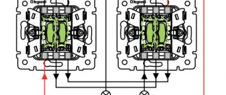
Connecting electronic ballasts to four lamps
As is the case with one or two lamps, the circuit does not require any additional elements. The electronic ballast module is connected directly to the ll.
Connection diagram for electronic ballasts 4x18 W (Example: Navigator NB-ETL-418-EA3)
Connection diagram for electronic ballasts 2x36 W (Example: ELECTRONIC BALLAST ETL-236)
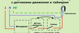
Connection diagrams for fluorescent lamps using EMF
EMPRA is an electromagnetic ballast, and in fact, an ordinary choke. In the circuit diagram for connecting the EMGR, a starter is required, which creates the first impulse to start the fluorescent lamp to glow.
Read, electronic ballasts and emballasts. What are the differences between ballasts
Connection diagram for a fluorescent lamp EMPRA
This connection diagram is used in most standard single-lamp local lighting luminaires of economy class.
Circuit inductive implementation
- Supply voltage 220 Volts;
- The inductor (LL) is connected in series to the power wire and lamp terminal 1;
- The starter is connected in parallel to terminals 2 and 3 of the lamp;
- Pin 4 of the lamp is connected to the second power wire;
- The circuit involves a capacitor, which reduces the voltage pulse, increases the service life of the starter and reduces radio interference when the lamp is operating.
Circuit inductive-capacitive implementation
The second connection circuit is called inductive-capacitive. In it, the inductor and capacitor (inductive and capacitive reactance of the circuit) are connected in series. The starter is still connected in parallel with the output of lamp 2-3.
Connection diagram for 2 fluorescent lamps up to 18 W (EMP)
The connection diagrams change slightly with two lamps. The most common two circuits are for lamps up to 18 W (series) and lamps 36 W (parallel).
In the first scheme, two starters are still involved, one starter for each lamp. The inductor is connected as in an inductive circuit. The power of the choke is selected by summing the power of the lamps.
Important! In this (series) circuit, it is necessary to use 127 (110-130) Volt starters. The lamp power cannot be more than 22 W.
In the second parallel circuit, two chokes (LL1 and LL2) are already involved. There are still two starters, one starter for each lamp.
Articles on the topic: electronic ballasts and electronic ballasts. What are the differences between ballasts
Important! This circuit uses 220-240 Volt starters. Lamp power up to 80 W.
Important note. Modern electronic ballasts are produced in a single housing. For connection, there are only contact pins on the case. The lamp connection diagram is indicated on the housing.
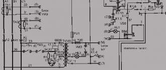
Circuits of electronic ballasts for fluorescent lamps
The equipment has a small number of elements. What functions they perform, as well as what they represent, we will discuss below.
The alternating voltage is absorbed by the diode bridge. Here it is straightened and smoothed using a filter capacitor. Typically, a fuse and a filter device are attached to the bridge to eliminate electromagnetic interference. Some foreign-made electronic ballasts do not have filters, and the capacity of the smoothing element is less than required, which causes problems in the operation of lighting equipment.
The voltage then goes to the automatic generator. Even by the name itself you can understand for what purpose it was installed here. In this case, this process occurs on one or more transistors, their number depends on the power. Transistors are connected to the transformer, which has three windings. They come in several types, the choice depends on the power of the lighting equipment.
Despite the fact that it has the name transistor, its appearance is unusual. Three windings, each of several turns, are wound around this device, which is a ferrite ring. Two have a management role, and one has a working role. The functions of creating pulses to turn the lamp on and off are performed by the controllers.
Possibility of starting with burnt-out equipment
Repairing fluorescent lamps also has its own little tricks. For example, there was an urgent need to start such a lighting device, but the starter was faulty, and there was no way to replace it. This circuit element itself serves to heat the filaments in the fluorescent tube.
Well, what if, for example, the throttle fails? Nowadays you can’t find it in all stores.
Throttleless activation
It is quite possible to prolong the operation of a burnt-out light fixture. There is a way in which you can turn on a fluorescent fluorescent lamp without a throttle and starter (connection diagram in the figure). Of course, this method is not suitable for everyone; you need to have at least a little understanding of electrical engineering.
Throttleless switching circuit
Voltage is supplied after a short circuit of the filaments. The rectified voltage doubles, which is quite enough to start the lamp (in theory, this function is performed by the inductor). Capacitors C1 and C2 (in the diagram) must be selected for 600 V, and C3 and C4 - with a rated voltage of 1,000 V. After some time, mercury vapor, of course, will settle in the area of one of the electrodes, and the light from the lamp will become much less bright. It will be possible to get rid of this simply by changing the polarity, i.e. simply by deploying the reanimated burnt-out LL.
Starterless inclusion
There are lighting devices that are designed exclusively for operation without a starter. Such lamps are marked RS. If such a tube is installed in a lamp equipped with a breaker, the lamp burns out very quickly. This happens due to the need for more time to warm up the spirals of such fluorescent tubes. The starter's durability is short, it often burns out, and therefore it makes sense to consider the possibility of how to turn on a fluorescent lamp without it. To do this, you will need to install secondary transformer windings. If you remember this information, then the question will no longer arise of how to light a fluorescent lamp if the starter burns out (connection diagram below).
Thus, without extra costs, you can even assemble a fluorescent lamp with your own hands.
Connection diagram without throttle and starter
Electronic ballast power supply - diagram
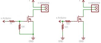
Imported transistors MJE13003, MJE13007, and in rare cases MJE13009 and their analogues are used as power switches. Transistors can be said to be created specifically for operation in network UPSs. Similar transistors are used in computer power supplies. So, first I want to present the main advantages of such a power supply.
- Compact size and light weight
- Low costs and low cost
- Reliability of operation
These are just the main advantages of our homemade block, but it also has other (hidden) advantages. Some UPSs only work under a certain load, in other words, the power supply will not be able to work when idle or with a low-power load. Quite popular ETs (electronic transformers), which are designed to power halogen lamps with a power of 12 volts, have this property. Our power supply turns on when mains voltage is applied and is capable of powering loads with power from fractions of a watt (LEDs, etc.) to 40-50 watts. Such a unit can be used as a laboratory power supply for a novice radio amateur.
The power supply is not afraid of short circuits at the output (instead, the electronic transformer fails after a second short circuit), has high operational stability and can operate for a very long time without turning off. The essence of reworking the ballast is to refine it. We need to wind a pulse transformer, which provides galvanic isolation from the 220 volt network and lowers the voltage to the level we need.
The transformer can be wound on almost any ferrite core (rings, armor cups or W-shaped core). The network winding contains 130 turns of wire 0.3-0.6 mm, the step-down winding should contain 8-9 turns, which corresponds to an output voltage of 12 Volts.
The voltage from the ballast is supplied to the transformer winding through a capacitor (select the capacitor voltage in the range of 1000-3000 volts, capacity 3300-6600 pF). It is advisable to wind the secondary winding of the transformer with several strands of thin wire (4 strands of 0.5 mm wire), the output is about 3.5-4 Amperes. It is also possible to use ready-made transformers from ET with a power of 50-150 watts.
To rectify the voltage, you should use powerful pulse diodes or diode assemblies from computer power supplies. From the domestic interior you can use KD213. When selecting diodes for a power supply from electronic ballasts, make sure that the maximum permissible current of the diode is in the region of 8-12 Amps; the diode itself should operate at frequencies of 100-150 kHz.
Very often, the cause of breakdown of an electrical appliance is a faulty battery. As a result, repairs or the purchase of new equipment are required. But you can avoid high costs by making a power supply from an energy-saving lamp yourself. All the necessary parts can be taken from a regular fluorescent lamp, the cost of which is low.
Design and principle of operation of electronic ballasts
Any electronic ballast consists of the following elements:
- device for current rectification;
- electromagnetic radiation filter;
- circuit power factor correction unit;
- voltage smoothing filter;
- inverter;
- choke or ballast for lamps.
The structure can be pavement or half-bridge. The first option has improved characteristics and is used in high-power lamps, from 100 W. The circuit effectively maintains the glow indicators and the voltage supplied to the cathodes.
Half-bridge circuits are more popular because Suitable for most household fluorescent lamps up to 50 W. Designs marked 2x36 support the connection of two 36 V lamps.
The operation of the device consists of the following steps:
- Turning on and preheating the filaments. This is an important manipulation that significantly extends the life of lighting sources. Without preheating, the lamp will not turn on at low temperatures.
- Generation of a high-voltage impedance pulse with a voltage of about 1.5 kV, which causes a breakdown of the gaseous medium inside the flask and starts the glow.
- Stabilize voltage and maintain it at the required level. The voltage to support combustion is low, which makes the circuit safe.