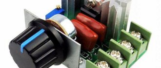
Potentiometers are adjustable voltage dividers for adjusting it when supplied to a powered device at constant current. Other names are variable or tuning resistor, but it is necessary to distinguish between the rheostat mode. The resistance of the part, and, accordingly, the voltage power can be changed, thereby adjusting a specific function of the device being serviced. It is potentiometers that regulate the light intensity of lamps (dimmers), LEDs, sound (simple selectors or equalizers), the rotation speed of fans, and small electric motors. The controls for these radio components are known to everyone: rotating knobs or sliders (on old stereos, TVs, tape recorders), software solutions can be used (via microcircuits), there is also an automatic, automatically controlled potentiometer.
Potentiometer concept
In this article we will use the following abbreviations:
- PT and RS - potentiometer, rheostat;
- I - current;
- U is voltage;
- R - resistance (resistance).
Other names for potentiometer:
- resistor: trimmer or variable (trimmer, variable). These are two different types of the same part in question, they must be distinguished, but sometimes these names are used as a general name. Here we mean these parts in potentiometer mode, not rheostat mode. By default, we will assume them in this inclusion option;
- voltage divider. The name most correctly reflects the concept of what a potentiometer is.
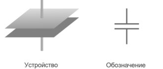
A voltage divider is the same resistor; the part is created according to its type and according to a similar principle. But an ordinary such element (“constant” “fixed”) provides a fixed amount of resistance that blocks the current in the circuit, resisting it, thereby lowering it according to Ohm’s law.
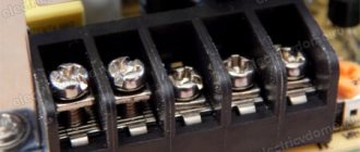
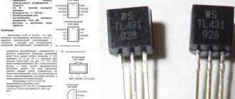
A variable/tuning resistor has a plate (like a car wiper, scraper) or similar element that runs with a constant (sliding) contact along the resistive (sensitive) part. In this way, the resistance is changed, and most importantly, the voltage is divided, that is, it is adjusted, decreased/increased. Therefore, such radio components are called “voltage dividers.” Below in Fig. Western standard part designation:
The name DC potentiometer is a combination of the phrases “potential difference” and “meter” - I measure, the term appeared at the dawn of the development of electronics and implies a measuring device. When setting up dimensional resistive coils with wire windings, the property of the part was used to measure the potential difference values, which classified it as a measuring type. So it is, it’s just that now these qualities are adapted to voltage regulation. This aspect of the application quickly became the main one and 95% of such elements, or even more, are manufactured specifically for controlling electrical parameters.
Dimming the brightness of your LED
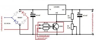
First of all, turn the potentiometer axis all the way counterclockwise, otherwise you may burn out your LED before starting the experiment. (Very few potentiometers increase or decrease resistance in a manner other than the one I describe here, but since you are using the potentiometer shown in Figure 1 , my description should be fairly detailed.) After this, make all connections as shown in Fig. 4 , being careful not to allow the metal parts of the alligator clips to touch each other. Now, very slowly clockwise, begin to turn the potentiometer axis. As a result, you should notice that the LED will glow brighter and brighter, and eventually, suddenly go out. So, have you experienced how easily modern electronics can be damaged? Throw away this LED. It will never light up again. Replace it with a new LED, but now be much more careful. To measure the voltage in a circuit that uses batteries, you need to select the mode on the multimeter for measuring voltage at direct current - “V” and “DC”, “V” or “VDC”, where DC (direct current) is direct current, like this is shown in Fig. 5 . Now touch the LED leads with the test leads. Try, while holding the probes in place, to slightly turn the potentiometer axis, first in one direction and then in the other. You should see a corresponding change in voltage across the LED terminals. We call this the potential difference between the two terminals of the LED.
Fig.5.
If you use a small incandescent light bulb instead of an LED, then when you measure, you will get a potential difference that will change to a much greater extent, since the light bulb behaves like a “simple” resistance, while the LED self-adjusts to some extent, changing its resistance by depending on changes in supply voltage. Now, to measure the potential difference between the potentiometer leads, touch them with test leads. The potentiometer and LED share all available voltage between themselves in such a way that when the potential difference (voltage drop) across the potentiometer increases, then the potential difference between the LED terminals drops, and vice versa ( Fig. 6, 7 ).
Fig.6.
There are several things to keep in mind. • If you add up all the voltage drops across each element in the circuit, the sum will be equal to the voltage supplied by the battery. • When measuring voltage, you are always measuring the relative voltage between two points in a circuit. • Connect the test leads of your device very carefully, like a stethoscope, without any disturbance or damage to the connections in the circuit.
Fig.7.
In Fig. 7 :
a — The device shows the voltage value on the LED;
b - The device shows the voltage value on the potentiometer.
Features of electrical parameters adjustment
To understand the operation of variable resistors, you need to know that always - in rheostat or potentiometer mode - both voltage and current change (U depends proportionally on I). Both operating algorithms are based on a change in resistance (R), which remains independent of the specified values. But it is precisely its adjustment on the variable that reduces/increases U and I.
Voltage dividers are resistors with a fixed resistance value. (ohm number) on it, and with a variable one set by an additional lever (scraper). This is a common element of electrical circuits, electronics, and household appliances. The controls are familiar to everyone - small round knobs, sliders, sliders, selectors.
Cleaning the trimmer with regular alcohol
The resistor in circuits can become dirty; its slider track becomes covered with a layer of dust over time. And in order to return the electrical resistance to its previous performance, you just need to clean it.
Cleaning trimmer resistors is quite simple and quick. It is best to use pure alcohol for these purposes. It is better not to use various products such as nail polish remover, moonshine, or cleaners, as they may contain impurities that negatively affect the cleanliness of the resistor.
To better master the material, we also recommend reading the following material: everything you need to know about stepper motors.
So, we disassemble the resistor (if it has a protective casing), for this it is usually enough to unbend the small metal clips on the resistor body itself, after which you need to remove this cover. Inside the resistor we will see a track along which the slider of the middle terminal of the resistor moves. It is this path that needs to be cleaned from dirt with alcohol.
It’s convenient to do this: take a syringe (let’s say 2 cc), fill it with alcohol, and carefully apply a few drops through the needle of the syringe directly onto the resistor track. After this, we begin to rotate this resistance in different directions so that the alcohol spreads throughout the entire track and thereby clears the way for the slider.
How to clean a resistor at home.
In principle, this is enough so that after assembling and installing the tuning resistor in our circuit workplace, we can enjoy its normal operation without previous problems. Although, if space on the resistor itself allows, you can also carefully go over it with a cotton swab, which will completely remove all dirt from the slider track.
It will be interesting➡ What is a thermal relay
Well, then we need to put our updated resistor back together and put it in our workplace. In most cases, after such cleaning, the electrical resistance is completely restored, and the intermittency of its operation disappears.
Difficult cleaning cases
In very rare cases, it is not a matter of dirt, but, for example, the destruction of this path as a result of excessive overheating. This can happen when too much voltage is accidentally applied to this resistor and the power of this resistor is not large enough to quickly dissipate the generated heat from the high current. This is where the variable resistor track heats up greatly, followed by its destruction. Cleaning with alcohol won't help here.
This resistor needs to be completely replaced with a new one that is known to work. And, of course, before installing a new resistor on the old circuit, check it so that the process of destroying the track does not repeat with a new resistance.
Unfortunately, not all types of variable and trimming resistors can be cleaned using the above method. Sometimes there is resistance in the solid body, which makes it impossible to reach the slider track.
Here you can go to extreme measures. Make a small hole in the body (with a 0.8-1 mm drill). Well, pour alcohol through it with a syringe through a needle. Next, again turn the resistor knob in different directions and then you need to wait until the alcohol has completely evaporated.
You can warm up this variable resistor a little (up to 50 degrees), this will speed up the evaporation of alcohol. Although pure alcohol is a dielectric, it does not conduct current through itself. Consequently, it will not negatively affect the operation of the variable resistor, even if there is some alcohol left on it, which will still evaporate.
Where and for what are voltage dividers used?
PTs normalize voltage; more often they are used to adjust application parameters (serviced equipment) within the normal values for which it is designed, when such a function is built into it, for example, sound volume, fan speed. The most common model is with manual adjustment, but there is also an automatic integrated potentiometer.
PT is also used when it is necessary to establish the desired mode of equipment in difficult conditions, when a certain level of electrical parameters can disable the application, or for research, for the purposes of maintenance, repair, experiments, and adjustment.
An increase/decrease in U supplied to the load, which also entails changes in current, is carried out by potentiometers or rheostats. We will look at the difference between them below. In fact, these terms do not denote the part itself (in all cases this is a variable resistor), but the modes of its inclusion in the circuit.
The most typical examples of what is regulated:
- power and other parameters (adjustment by equalizers) of sound, video brightness/shades, light (dimmers);
- speed of low-power electric motors of household appliances and toys;
- Fans with variable speed settings have voltage dividers. Even those whose rotation intensity is meant to be set to constant operation with a certain value? often have a trimmer on the chip;
- generator frequency;
- calibration of electrical circuits, on microcircuits for adjusting electrical parameters by voltage (its output power).
- Precision, including automatic high-precision potentiometer is used in angular and linear displacement sensors.
Variables/trimmers are used wherever adjustment of the output voltage is required. But you need to understand that such a device is needed only for high-resistance loads and low currents. Where these parameters are large, rheostats are used. For example, the dimmer may contain a DC, but if the incandescent lamp is powerful, then it will be useless and a PC must be used. The same applies to electric motors: low-power ones can be regulated by PT, but powerful power plants in vehicles have RS. In order to study where to apply what, you need to do calculations using Ohm's formulas.
Potentiometers.
Potentiometers are used as smooth gain controls, volume and tone controls, serve for smooth adjustment of various voltages, and are also used in tracking systems, in computing and measuring devices, etc.
A potentiometer is an adjustable resistor that has two permanent terminals and one movable one. The permanent terminals are located at the edges of the resistor and are connected to the beginning and end of the resistive element, forming the total resistance of the potentiometer. The middle terminal is connected to a movable contact, which moves along the surface of the resistive element and allows you to change the resistance value between the middle and any extreme terminal.
The potentiometer is a cylindrical or rectangular body, inside of which there is a resistive element made in the form of an open ring, and a protruding metal axis, which is the handle of the potentiometer. At the end of the axis there is a current collector plate (contact brush) that has reliable contact with the resistive element. Reliable contact of the brush with the surface of the resistive layer is ensured by the pressure of a slider made of spring materials, for example, bronze or steel.
When the knob is rotated, the slider moves along the surface of the resistive element, as a result of which the resistance changes between the middle and extreme terminals. And if voltage is applied to the extreme terminals, then an output voltage is obtained between them and the middle terminal.
The potentiometer can be schematically represented as shown in the figure below: the outer terminals are designated by numbers 1 and 3, the middle one is designated by number 2.
Depending on the resistive element, potentiometers are divided into non-wire and wire.
1.1 Non-wire.
In non-wire potentiometers, the resistive element is made in the form of a horseshoe-shaped or rectangular plate of insulating material, on the surface of which a resistive layer is applied, which has a certain ohmic resistance.
Potentiometer and rheostat: what is the difference
Let's consider RT in detail, since the properties of potentiometers will also be revealed in the process. So, the same variable resistor can be mounted on the circuit in two ways, creating two modes:
- parallel connection - PT. The potentiometer connection usually uses all 3 pins.
- sequential - rheostat. Only 2 contacts are used.
“Potentiometer” and “rheostat” are simply different options for including the same variable resistor in a circuit, respectively, in series or parallel. Both parts work specifically with R, U, I. But the proportionality of the changes is different, in the first case the voltage is regulated to a greater extent, in the second - the current.
The rheostat has two outputs, the potentiometer has three (if used as the first, then only two contacts are connected). That is, the PC is included in the circuit like an ordinary resistor. Both are non-polarized and can work in reverse.
PT and PC are connected differently. The second, unlike the first, is usually an industrial device or on powerful equipment. Some schools taught lessons with a rheostat, so some may remember its shape: a large ceramic tube with a nichrome winding and a slider on the middle terminal that is not connected anywhere. RS has high power (passes powerful current) and low resistance (up to tens of ohms). It has significant inductance, which is taken into account in HF devices.
Voltage dividers are usually low-power, so they are rarely suitable for the role of PCs; in production, variables up to 10 W are positioned as the first, and from 10 W - as the second.
Variable as a rheostat
RS changes the overall resistance. circuits - it is this property that is important here; it is used in its full, most effective form to control (limit) the current.
It is connected to the circuit only in series: the switched-on variable is called a rheostat (this is the operating mode).
You can imagine the circuit as such, consisting of two ordinary resistors connected in series, that is, the slider divides the PC coil into the indicated elements. By adjusting R, the parameters of these resistors and, accordingly, the current in the circuit are reduced/increased.
Schematic designation and pinout
Unlike fixed resistors, adjustable resistors do not have two terminals, but at least three. Why at least? Because there are models with additional outputs - there may be several of them. On electrical diagrams, variable and tuning resistors are indicated by rectangles as constants, but have an additional output, which is schematically represented as a broken line abutting the middle of the image. To distinguish the variable from the trimmer, an arrow is drawn at the end of the variable at the end of the third input; the trimmer is depicted by a longer perpendicular line without an arrow.
Designation on the diagrams of variables and trimming resistors
If we talk about the location of the pins, then the middle pin is connected to the slider, the outer ones are connected to the beginning and end of the resistive element.
Variable resistor pinout
Variable resistor as potentiometer
An appropriate and more correct other name for PT is a voltage divider. If we take the above diagram, then these are also 2 or more resistors with a serial connection, but such a node of them (chain) is connected in parallel to the source, which allows adjusting their resistance to obtain exactly the voltage required for the load.
Difference in scope
The potentiometer has low power and is used for relatively low-power devices: TVs, audio equipment, low-power dimmers, underfloor heating controllers, boilers, as converters, for adjusting the speed of weak motors, for fans, for example, computer coolers, ventilation systems.
We will characterize the use of RS with a selection from a thematic site:
The areas of use at first glance are similar to PTs, but this is not the case: RSs are used where there are high currents and the operation of devices depends on them: powerful power tools, electric motors of vehicles and production ones, in industry.
We can say that the alternator for lamps operating with high currents and the same loads in the form of electric motors, for electric furnaces, and machine tools is used only in rheostat mode.
The clearest explanation for the difference in application
With a potentiometer, the current from the source is spent several times higher than the load needs. At PC, the value of this value is equal to that at the load. Therefore, the latter is used to adjust I and U on low-resistance loads, they have a pattern - they consume relatively more powerful currents, and potentiometers - for high-resistance loads, since they are usually powered by this value with a small value.
Features in appearance
The variable can be both, but if it is manufactured for rheostat mode, then it has a typical size for it: with two terminals, with a large resistive part (winding), usually a large, thick, heavy wire resistor and its shape is much larger, what about the parts for PT.
It is necessary to distinguish between terms, since sometimes confusion arises in different sources: for example, the phrase “potentiometer in rheostat mode” is not entirely correct, since this designates two different connections, but the phrase “variable resistor in rheostat (or potentiometer) mode” is correct. Although erroneous lexical formations are often found even on technical websites, the main thing here is that the user distinguishes what is being said.
If a part has two outputs, then its state is only PC, but if there are three, then such a part can theoretically be used as it (we described this above), but in reality it is intended specifically for the DC mode.
Basic properties of variable resistors
When a person has a clear idea of the conventional elements of graphic display on diagrams, then he has the problem of transferring the drawing into reality. You need to find or purchase individual components of a ready-made circuit. Today there are a large number of stores that sell the necessary parts. You can also find elements in old broken radio equipment.
A variable resistor must be present in any circuit. It is found in any electronic devices. This design is a cylinder that includes diametrically opposed terminals. The resistor creates a limit on the flow of current in the circuit. If necessary, it will perform resistance, which can be measured in ohms. A variable resistor is indicated on the diagram in the form of a rectangle along with two dashes. They are located on opposite sides inside the rectangle. Thus, a person denotes power on his diagram.
The equipment, which is found in almost every home, includes resistors with a certain value. They are located along the E24 row and conventionally indicate the range from one to ten.
Algorithm for the operation of a potentiometer, comparing it with that of a rheostat
It is appropriate to reveal the principle of operation simultaneously for PT and RS, since we are essentially talking about one part in different modes:
The principles of operation are revealed by the laws of the process of changing current and voltage. For the rheostat, let's take a light bulb as the load (in the diagrams above). With increasing resistance on PC the same thing happens with the general resistance. (Rtotal), and the same current decreases. Consequently, both I at the load and the voltage across it drop.
The decrease/increase in current in the circuit is not inversely proportional to that of the resistor. RS, because in addition to the adjustable R rheostat, there is also R, but unchanged - at the load. Only when Rreost >>Rн will these quantities change with close to inverse proportionality. On the contrary, if Rreost
Now we will explain the action in the process of describing how U of the load changes: the total value at the current source (Uist = Un + Upeost) between RT and U is proportional to their R:
When this decreases on the PC, a redistribution of the total U occurs and at the same time the U of the load, and, consequently, I through it increases.
Now let's move on to the potentiometer. This is the same rheostat, but connected differently and the name “voltage divider” most accurately reflects its essence.
The PT regulates current and voltage on high-resistance (we focus on this) equipment, that is, with this parameter, the use of RS is inappropriate, if not completely impossible. A variable resistor as a PT is connected to the source by the lower terminals A and B, which are the ends of the winding, enclosed (crimped) in a way convenient for inclusion in the circuit. Unlike a PC, terminal C is connected to the consumer and A and B are also connected to it.
Operating principle of PT:
- voltage is applied to the entire resistor;
- but for the consumer only part of it is removed, which can be adjusted by moving the slider D between points A and B;
- in this case, the indicated load value Un will vary from 0 to the maximum U of the source.
U at the consumer can fluctuate in direct proportion to the length of the segment ^AC, but it can also have a more complex relationship U = f(l), determined by the ratio of R load and R potentiometer. There are such patterns:
Connecting a variable resistor
Connecting a variable resistor or how to connect a variable resistor. Many people don't know how to connect a variable resistor. And so let's start everything very simply. The variable resistor is shown in Figure 1.
The variable resistor has 3 terminals, two side terminals and one of the terminals in the center. From this terminal the resistance is removed, which is adjustable relative to the other two terminals of the variable resistor (Figure 2). If we connect the “plus” to one side terminal, and the “minus” terminal of the power source, for example, to 12V, to the other terminal, then when we rotate the variable resistor knob on the central terminal, we will get a voltage relative to the “minus”, which will vary from 0 to 12V . When choosing a variable resistor, it is necessary to select its resistance of at least a few kOhms and up to several hundred kOhms, depending on the voltage of the power source. It is better not to connect a powerful load to a variable resistor, unless it is a special powerful resistor for high power. Usually, for various automation circuits and frequency converters, a variable resistor with a resistance of about 10 kOhm or so is used, since the current, as a rule, is only a few milliamps, then any power of the variable resistor can be taken.
If you use a variable resistor on an alternating current network of 220V, for example in a thyristor light controller, then the main thing to remember is that the metal body of the resistor may be energized and you must be careful and it is advisable to put a special insulating cap on the handle of the variable resistor.
Source
Calculation, selection of potentiometer parameters
So, the potentiometer is designed to regulate the voltage specifically on a high-resistance load - it must have resistance. higher than PT, otherwise the number of Volts will be determined by it, and the adjustment function will disappear.
The main features for calculating PT are:
- resistance The PT should be much smaller (Rpot<<Rн) than that of the load. This is not necessary, but if not observed, further calculations will become more complicated - you will have to take into account the current on it. The recommended values are at least 10 times lower, but better - 20, 30, 100. The lower, the better, but not excessively, otherwise the requirements of the following points will not be met;
- U of the current source must be suitable, the PT must withstand it (Inom.pot×Rpot) > Usource. In this case, the number of Amperes flowing through the alternator (Ipot = Uust/Rpot) should be less than the current rating of the part;
- the current passing through the PT (Ipot = Uust / Rpot) should not be higher than the nominal value according to that of the source (Ipot < Inom. source);
- if there are several PTs and they all fit the above conditions, then take a product with higher resistance - it will consume less current, which is especially significant when used with galvanic batteries.
Another nuance of adjusting current and voltage with a rheostat and potentiometer:
- both make it possible to obtain U at the load equal to or lower than U of the source;
- but with PT you can lower the above value to 0, which is extremely difficult, almost impossible, to achieve from RS.
The Importance of Power Dissipation
When selecting a variable resistor, the resistance rating is taken into account first, but current rating, in other words, power dissipation, is no less important to pay attention to. The two parameters are interrelated. Let's explain with an example. The circuit contains a resistor with a certain R, but it turns out that this value should be significantly lower, that is, the part must be replaced.
They put in an element with a significantly lower R, and it would seem that the problem is solved, but here there is a danger associated with ignoring Ohm’s law. R on the resistor was significant, U of the circuit was fixed. When the value of the variable was lowered, the total R of the line fell, as a result, the current increased. If you install a PT with the same dissipation power, then with increased I it may not withstand the load, the consequences are traditional - overheating, even to the point of fire.
Approximate norm: with a nominal value of 10 Ohms, a current of about 1 A should flow through the circuit - this is the power dissipated by the resistor. When choosing, be sure to look at this permissible value for the part.
3. Designation of variable resistors on diagrams.
On circuit diagrams, variable resistors are designated in the same way as constant ones, only an arrow directed to the middle of the case is added to the main symbol. The arrow indicates regulation and at the same time indicates that this is the middle output.
Sometimes situations arise when requirements for reliability and service life are imposed on a variable resistor. In this case, smooth control is replaced by step control, and a variable resistor is built on the basis of a switch with several positions. Constant resistance resistors are connected to the switch contacts, which will be included in the circuit when the switch knob is turned. And in order not to clutter the diagram with the image of a switch with a set of resistors, only the symbol of a variable resistor with a step control
. And if there is a need, then the number of steps is additionally indicated.
To control volume and timbre, recording level in stereo sound-reproducing equipment, to control frequency in signal generators, etc. dual potentiometers are used
, the resistance of which changes simultaneously when
the common
axis (engine) is rotated. In the diagrams, the symbols of the resistors included in them are placed as close to each other as possible, and the mechanical connection that ensures the simultaneous movement of the sliders is shown either with two solid lines or with one dotted line.
The belonging of resistors to one dual block is indicated according to their positional designation in the electrical diagram, where R1.1
is the first resistor of the dual variable resistor R1 in the circuit, and
R1.2
is the second. If the resistor symbols are at a great distance from each other, then the mechanical connection is indicated by segments of a dotted line.
The industry produces dual variable resistors, in which each resistor can be controlled separately, because the axis of one passes inside the tubular axis of the other. For such resistors, there is no mechanical connection that ensures simultaneous movement, therefore it is not shown on the diagrams, and membership of a dual resistor is indicated according to the positional designation in the electrical diagram.
Portable household audio equipment, such as receivers, players, etc., often use variable resistors with a built-in switch, the contacts of which are used to supply power to the device circuit. For such resistors, the switching mechanism is combined with the axis (handle) of the variable resistor and, when the handle reaches the extreme position, it affects the contacts.
As a rule, in the diagrams, the contacts of the switch are located near the power source in the break of the supply wire, and the connection between the switch and the resistor is indicated by a dotted line and a dot, which is located at one of the sides of the rectangle. This means that the contacts close when moving from a point, and open when moving towards it.
Design and types of variable resistors
A potentiometer is primarily an analog electromechanical part; there are also digital types, but they are still not very common. The wiper can also be moved using electrical means, not only manually. Movement can be angular (rotation) or linear (straight); Usually it is manual, but there is also an automatic, application-configurable potentiometer.
Potentiometer structure (the first two parts are main):
- resistive element;
- a plate (wiper, scraper) with a sliding contact moved by a handle (selector, lever) along the above part;
- terminals at each end of the part;
- mechanism that moves the wiper (shaft, slider block), bushing, bearing
- a housing in which the resistive part is enclosed.
The described device can be taken as a general principle, which is implemented in one form or another in all types of radio components; string and digital PTs are also based on it, but with their own specifics.
The resistive part of inexpensive variables is often made of graphite. Sensitive wire, plastic with carbon particles, and a mixture of ceramics and metal (cermet) are also used. For options with conductive tracks, polymer conductive pastes with carbon, wear-resistant resins, solvents, and lubricants are used. To summarize, according to the design of the case, the potentiometer has its own types and types in the form of pots (barrels, boilers), strips and chips (trimmers).
According to the material of the sensitive part
Wire - Constantine or Manganin wires are laid evenly in a horseshoe in the body. The slider slides along the turns, touches the next one before leaving the previous one - this is how smooth adjustment is achieved.
Thin film. The sensitive part is a horseshoe-shaped frame of a dielectric plate with a thin film: carbon, boron, metallized, composite materials. Trimmers and trimmers are often like this
By number of contacts
There are single-element models - these are standard variables. There are multi-element ones - double, triple, and so on - then there are more contacts for each such part. There are also products with contacts for the switch (below in the figure).
Rotary (circular, disk) variables
The most common variables are rotary ones. They can be equipped with a switch, usually triggered in the extreme counterclockwise position. Thus, you can immediately, without a separate element, turn off/on radio receivers such as equipment: for example, the device starts after a click when turning the selector at minimum volume, then it can be increased.
Pins 1 and 2 are also on regular resistors - of a constant value. Resistance is created by a special coating, an array of conductive alloy (including in the form of film, spraying), and a wire winding (nichrome and the like) on the “body” between them. For variable type, a third terminal is added (for the scraper), connected to the “engine”, a movable plate (wiper), moved with a sliding contact along this segment; for rotary types it is in the form of a horseshoe (arc).
If you turn the knob, R changes between 1 and 3, from 0 to the value stamped on the device body. The same thing happens between 2 and 3 “upside down”: when R between 1 and 3 increases, then between 2 and 3 it decreases and vice versa.
Linear, with sliders
Linear (sliders) have the shape of a plate, bar, that is, a longitudinal resistive element. The adjustment tool is a slider that slides along rather than rotating. The disadvantage of such models is that they are less protected from dirt: dirt can get inside through any part of the slot, even though there is a slider seal. The advantage is better visualization of the settings indication.
For rotary models, the position of the handle is often impossible to determine, especially if a “bare” resistor is mounted - for this you need to do calibration. If there is a scale, then it is perceived less conveniently. On the linear type, the setting position is visible even without the indicated one - by the position of the slider. For example, for equalizers and faders, you can determine the adjustment positions, evaluate the overall picture of the settings of a dozen or more sliders on the control panel, without looking too closely. In addition, linear FETs are usually more accurate because the resistive part is longer.
Multi-turn
A conventional circular variable makes complete movement of the adjusted point in 1 turn of the adjustment screw and is incomplete; the horseshoe should not close. For some tasks they are not accurate enough. For special sensitivity there are multi-turn options. They complete the described cycle in a certain number of revolutions, which greatly reduces errors. For example, turning the selector of a single-turn model with a nominal value of 10 kOhm half a turn will change the resistance. at 5000 Ohms, if the tolerance is 10%, then it will give an error of 500 Ohms. Multi-turn potentiometer 10 rpm with the same parameters, with a similar rotation of the lever, it gives a deviation of only 50 Ohms - 0.5% of the nominal value.
On average, turning the selector by the same angle gives an accurate setting one-tenth better than single-turn models.
Strings
A special subtype are string voltage dividers; they are controlled by a flexible cable and a spring-loaded coil. They are used for measurements on moving objects, for measuring linear position in industry, manufacturing, medicine, robotics, and on automated production lines.
Particularly accurate
Rotary or linear PTs with fixed positions marked with clicks are special discrete precision models made up of several resistors. They are used in testing equipment and on particularly precise equipment.
Automatic
The adjustment is not done manually, but by automatic application.
Twin
Several resistors can be located on the same shaft with their sliding scrapers, which makes it possible to regulate 2 or more channels in parallel. Used in audio amplifiers.
Trimmers (trimmers, presets)
Trimmers, also known as trimmers or pre-installed ones, are standard sizes for soldering onto a board. When a manufacturer creates a microcircuit, the part is soldered in and the required position is immediately set. It is assumed that it is the best for the device and it is not recommended to change it, except for the purposes of repair or special configuration cases.
Although there are also parts that require constant adjustment, for example, when such a standard size is appropriate for a particular device.
Digital
Digital PTs are becoming popular, which are integrated circuits without moving parts that allow you to adjust your own R programmatically with a given step.
Types and types of device
There are many types of trimming resistors on the market today. These are non-separable trimming resistors of type SP4-1, filled with epoxy compound, and intended for defense equipment, and trimmers of type SP3-16b for vertical mounting on a board.
It will be interesting➡ Quartz resonators - operating principle and scope of application
In the manufacture of household equipment, small trimming resistors are soldered onto the boards, which, by the way, can reach 0.5 watts in power. In some of them, for example in SP3-19a, metal ceramics are used as a resistive layer.
There are also very simple tuning resistors based on varnish film, such as SP3-38 with an open case, vulnerable to moisture and dust, and with a power of no more than 0.25 watts. Such resistors are adjusted with a dielectric screwdriver to avoid accidental short circuits. These simple resistors are often found in consumer electronics, such as monitor power supplies.
Some trimmer resistors have a sealed housing, for example R-16N2, they are adjusted with a special screwdriver, and are more reliable because dust does not get on the resistive track and moisture does not condense.
Powerful three-watt resistors of the SP5-50MA type in the case have holes for ventilation, in them the conductor is wound in the shape of a toroid, and the contact slider slides along it when the handle is turned with a screwdriver.
In some CRT TVs you can still find high-voltage trimming resistors, such as HP1-9A, with a resistance of 68 MOhm and a nominal power of 4 watts. Essentially, this is a set of cermet resistors in one package, and the typical operating voltage for this resistor is 8.5 kV, with a maximum of 15 kV. Today, similar resistors are built into TDKS.
In analog audio equipment you can find slider or slide variable resistors, such as SP3-23a, which are responsible for adjusting volume, timbre, balance, etc. These are linear resistors, which can also be double, such as SP3-23b.
What do linear resistors look like in a diagram?
Trimmer multi-turn resistors are often found in electronic equipment, measuring instruments, etc. Their mechanism allows you to precisely regulate the resistance, and the number of turns is measured in several tens.
The worm gear allows the sliding contact to turn slowly and move smoothly along the resistive track, allowing the circuits to be tuned very, very accurately.
It will be interesting➡ Varistors - what they are, operating principle, characteristics and parameters.
For example, the SP5-2VB multi-turn tuning resistor is adjusted precisely by means of a worm gear inside the housing, and to completely pass the entire resistive track you need to make 40 turns with a screwdriver. Resistors of this type in various modifications have a power from 0.125 to 1 watt, and are designed for 100 - 200 adjustment cycles.
This is not a complete overview of the types and types of parts. As we can see from the previous description, tuning resistors are inherently close to variables, but strictly speaking, they are not. This video briefly but clearly describes how to convert a trimmer resistor into a variable resistor.
Types according to the “cone” - the nature of the change in resistance
“Cone” or “law” is the relationship between resistance. and the position of the scraper. Manufacturer controlled. Any ratio is possible, but for most tasks linear and logarithmic PTs (“sound cone”) will suffice.
A letter code may be used, but this is not standardized; it may be different for different manufacturers, but usually the marking is as follows:
- Asia and the USA. A - for logarithmic, C - for inverse logarithmic (rare, exponential) and B - for linear taper;
- Europe - A for linear, C and B for logarithmic, F for its inverse version.
Explanation
The percentage relating to the non-linear cone refers to the resistance index. at the midpoint of shaft rotation. The 10% cone of a log measures 10% of the total R on it. That is 10% logarithm. a cone on a 10 kOhm PT gives 1 kOhm at the indicated mark. The higher the percentage, the steeper the logarithm. curve.
How voltage dividers are shown in diagrams
In order for the reader to distinguish the details more deeply, we indicate the graphics for PT and RS.
Designation of rheostats:
Designation of voltage dividers:
Designation of a simple (fixed) resistor:
Potentiometer connection
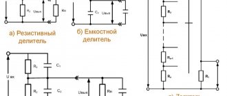
To begin with, we present a block of the most typical schemes. It must be said that the PT can be connected not only as a PC, but also as a simple fixed resistor (options in Fig. 3):
Below are the most common schemes (notations according to Western standards):
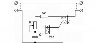
It must be said that the traditional wiring diagram for a potentiometer frequency switch always recommends connecting an “extra” pin; a break in the “moving contact - horseshoe” line is not excluded, which can lead to unpleasant consequences.
The diagrams for how to connect a PT are extremely simple; in fact, there is only one option - in parallel to one of the power wires.
For example, this is what the regulator on a computer cooler looks like. In this case, polarity does not matter. Take any cooler power supply wire, cut it, one end is soldered immediately to the first and second (middle) contacts, the second to the remaining one. That is, on the first 2 contacts there is one end of the wire (they are soldered to the same conductor), the third contact is the other end, as if standing alone.
The complexity of some circuits: you need to know which wire to connect to, that is, which power line to regulate, for example, if you are connecting an external potentiometer for variable-frequency electric drives to adjust the intensity of rotation of electric motors, when adjusting PID controllers.
In such cases, they are guided by the schemes of the manufacturers or authors of such improvements, the recommendations of the masters; all the information is available online on special forums and thematic sites. Below is an example of connecting to a frequency converter:
How a variable resistor works and connection diagram
In order to make the most of the technical capabilities of such a “scientific miracle” as electric current, it is necessary to remember the safety rules for operation and direct assembly of the system.
The picture shows a variable resistor
To regulate voltage
Initially, you need to know what this or that device consists of. This will greatly simplify working with it. Anyone who is familiar with electricity knows that a resistor is always used in all circuits. This is a special electrical circuit element that is used to regulate and monitor various technical parameters of the network. For example, it can be used to regulate the resistance indicator of both a separate section of the circuit and several independent parts as a whole. Today, a variable resistor is widely used to regulate voltage; it is worth talking about it in more detail.
A variable resistor is usually understood as an electrical part used to fit into the main part of the device and necessary to monitor the voltage in the network.
At the moment, there are the following options for variable resistors:
The picture shows an imported variable resistor
Depending on the type and variety of the part, they can be used not only to create elementary circuits, but also to assemble technical circuits for use in heavy industry.
Different types of variable resistors in the picture
Types of resistance
Today, electrical elements of the following types are sold on the territory of the Russian Federation:
How to connect?
In order to independently connect an electrical element to a working circuit, you must read the following information:
Now we begin to familiarize ourselves with the resistor and its insertion into the system. At the moment, there are a large number of different schemes for inserting a resistor. It can be used as a variable resistance source or potentiometer. Everything will directly depend on the type of connection of pin number 3. It is worth considering the connection of a resistor using an example.
Instructions for connecting a resistor to regulate voltage:
Video
Watch the video all about resistors:
The main thing that a person should remember when assembling a circuit is the need to follow the rules and observe safety measures. Before directly turning on the circuit, it is necessary to check all soldering and insulation points. This is the only way to use the assembled device for a long period of time.
Source
Examination
Checking the potentimeter is done with a multimeter:
- the resistance measurement mode is set, the probes touch the two outer contacts - the tester should show a value equal to the nominal one with a permissible deviation. Move the slider and observe how R changes on the multimeter display;
- the wire winding may be torn, the contacts may come loose - then the break is checked as standard - the tester is set to “continuity”, the two outer contacts are touched with probes: 1 - break; 0, digital values tending to it or beeping (if there is a buzzer) - the circuit is intact.
How to choose
The process of how to select a voltage divider involves studying the following parameters (some of the data is in GOST 10318):
- priority, ratings for: resistance;
- to the utmost slave tension;
- by power (dissipation);
- tolerance (errors);
How are they labeled?
Traditional markings, known since Soviet times: PTP, PLP, PPML, PLP, RPP, PPBL, PPMF. What should be indicated on the product is regulated by GOSTs 9245, 8.478-82. The alphanumeric characters themselves are found in OST 11.074.009 (current), GOST 13453 and 3453 (outdated).
New marking:
But it must be said that in modern conditions there is no single standard, so you need to look at the product specification from the manufacturer.
Repair
If a contact falls off, it can be soldered, but this is usually difficult to do, much less it is impossible to repair a mechanically damaged track or wire. In case of such breakdowns of functional parts, especially the resistive segment, the variables are not repaired.
If the functional parts are without mechanical damage, then you can try the following methods:
- restore the sensitive track: o lightly bend the spring of the movable contact with the lead of a simple pencil (consists of carbon) and draw along the sensitive layer. Method for thin film models;
- o grind the same stylus, mix with lithol or a similar lubricant, lubricate the path along which the slider walks;
How to increase the resistance of a variable resistor
To increase the resistance you will have to work a little, but you can double the resistance:
- disassemble the slider resistor, remove the “horseshoe” with the conductive layer from it:
- Using a knife or fine-grained sandpaper, carefully remove part of the graphite layer from the outer and inner ends of the track along which the slider moves.
It is much easier to reduce the resistance - you need to connect a constant resistance in parallel to the resistor in the circuit.