Methods for checking the throttle position sensor (TPS)
Previously, we wrote about the symptoms that may appear when the throttle position sensor breaks down.
But such symptoms often cause breakdowns of other sensors or engine components. Therefore, before purchasing a new TPS, the existing sensor must be checked for functionality. The TPS is mounted on the throttle body. This sensor contains a variable resistor (or contact points, depending on the model) that transmits a signal to the electronic engine control unit. The sensor readings depend on the throttle position.
When the driver presses the gas pedal, the damper rotates, increasing the flow of air into the intake manifold. When the engine is running, throttle position (and data from other sensors) tells the computer how much fuel the engine needs at a given moment.
Therefore, without the correct signal coming from the TPS, problems arise with the fuel-air mixture. Note that checking the throttle position sensor is not very difficult. You will need information about the factory settings of the sensor, after which it is checked using a digital multimeter.
You can buy a multimeter in many stores; this simple diagnostic device will come in handy more than once.
The most common malfunction of the throttle sensor is wear, short circuit or open circuit in the electrical circuit or resistor. With the help of this article, you can understand how to check the TPS with a multimeter in just a few minutes. This will help you understand whether the element needs to be replaced or whether the problem is not with it.
Symptoms of a TPS malfunction:
- lean or rich fuel mixture;
- ignition problems;
- incorrect signals for other actuators;
- rough idle;
- failures during acceleration;
- twitching;
- stopping the engine.
What structure do the sources of light flux have?
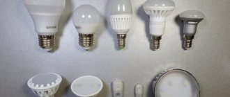
Daylighting is the most economical lighting option. At the same time, it is best suited for the eyes, making it an excellent alternative to all currently existing room lighting options. To create daylight, different types of fluorescent lamps are used today. Such lamps can be classified according to the shade and brightness of the light emitted:
- warm white;
- cold white;
- yellowish tone.
But to increase their safety during operation, it is customary to use a special device - a choke. All fluorescent lamps are equipped with it.
Note! When purchasing a fluorescent lamp, be sure to ask the seller about the warranty and other accompanying documentation for the purchased product. This way you will definitely buy a quality device for your needs.
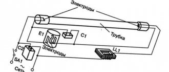
What is a throttle? Externally, the inductor has the appearance of an inductor, which has a special ferrimagnetic core. This is a detail that is necessary for stable operation of any lamp when creating daylight. In fact, the choke is part of an energy-saving light source installed in the lamp. If it malfunctions or its performance decreases, blackening appears at the ends of the lamp. The task of this part is to control the voltage created at the output contacts of an energy-saving light source. Very often, the choke is part of fluorescent lamps. Here, to ensure that the source of daylight does not go out, ballast is created. It is capable of maintaining the current in the contacts of the lighting device at the required level.
Note! According to current standards, such ballast must be connected in series. Then a starter is connected in parallel to it. He is responsible for lighting the lamp.
This structure and connection method plays an important role in the performance of the lamp used to create daylight in the room. Therefore, if there are malfunctions, then first of all you need to check the throttle. We will tell you how to do this below.
How to check a ballast choke without a multimeter
Without special measuring instruments, a faulty ballast may be indicated by the fire snake effect. You can visually observe it inside the lamp.
What does this mean? And this means, first of all, that there is an excess of the maximum permissible current. Because of this, the charge lost stability.
The lamp may also glow intermittently or flicker. If the ballast breaks down, the lamp will not light up the first time.
As a result, the starter will constantly start and stop, start and stop. From such frequent starts, blackening appears near the spirals at the ends of the lamp.
Another way to check without measuring instruments and a multimeter is with a test light. Its power should be approximately the same as the power of the throttle itself.
Connect it in series according to the following diagram with the ballast and watch how it lights up.
- if it doesn’t light up at all, there is a break in the ballast, the throttle is faulty
- burns brightly - there is an interturn short circuit in the ballast
- blinks or lights up at half intensity - the throttle is working
Structure of a fluorescent lamp
Such daylight sources necessarily contain a glass bulb of various shapes in their design. It contains spiral electrodes and an inert gas (mercury vapor). The top of the flask is covered with a special layer of phosphors.
The principle of operation of the lamp is as follows:
- when electric current flows to the electrodes (spirals), they heat up;
- as a result of heating the spirals, the gas is ignited;
- under the influence of it the phosphor begins to glow.
Due to the fact that the electrodes have limited dimensions, the voltage available in the network is not enough to ignite the electrodes. This is what the throttle is used for. And to prevent excessive overheating of the coil, a starter is installed in the lamps. After igniting the gas, it starts processes that lead to the switching off of the electrodes.
Characteristics of electronic ballast
Electronic ballasts belong to the category of modern devices in which the disadvantages of an electromagnetic choke are almost completely eliminated. Schematically, such an element is a single unit that starts the lighting device and supports the combustion process by forming a certain sequence in changing the voltage level.
The advantages of electronic ballast are presented:
- any launch speed;
- no need to install a starter;
- flicker is excluded;
- maximum luminous efficiency;
- compact size and light weight of the device;
- optimal operating conditions.
This is what electronic ballast looks like
Electronic ballasts are an order of magnitude higher than electromagnetic devices, which is due to the complexity of the circuit with the presence of filters that correct the power factor of moments, an inverter and ballast. Some models of electronic devices are complemented by a system of protection against turning on the lighting device without a lamp.
The ease of use of electronic ballasts in energy-saving fluorescent lamps is due to the installation of light sources directly into the base of standard sockets.
Checking the incandescent lamp
In most cases, a faulty incandescent lamp can be determined by visual inspection. If the spiral inside the bulb is damaged, then further operation of the electric light source is impossible.
Sometimes damage to the conductors occurs in the places where the contacts are soldered or in the area between the base and the spiral. It is almost impossible to determine such a breakdown by eye, so if the spiral is intact, you should use a multimeter to make sure there is no break in the circuit. If the glass bulb is made of opaque glass or has been painted, then without a tester it will also not be possible to determine the internal break of the conductor.
How to check a lamp with a multimeter (sequence of actions):
- Set the multimeter to ringing mode.
- Connect the probes to the contacts of the incandescent lamp (polarity does not matter).
The serviceability of the electric lamp will be determined by a sound signal. The presence of electric current passing through the inner spiral can also be determined by measuring the resistance of the light bulb. For this purpose, the multimeter should be switched to resistance measurement mode, and then also connect the probes to the metal contacts of the light source.
If, as a result of the test, the display of a digital device shows an infinitely high resistance or there is no sound signal, then the incandescent lamp will need to be replaced (when using a pointer device, there will be no mechanical movement of the indicator). To make sure that the cause of the lamp malfunction is an open circuit, you should carefully inspect the contacts of the electric light source. Even if there is a slight oxide present, they must be moistened with alcohol and cleaned with a toothbrush or any non-metallic hard object, and then re-diagnosis must be carried out.
Using a multimeter, you can diagnose an open circuit in a car light bulb. If you need to check the head lighting element, then you should pay attention to the fact that such devices use 2 threads designed for 12 Volts, which must be ringed separately.
There are no differences in how to check a halogen lamp of the same voltage. Such a light source differs from a conventional element only in the use of an inert gas in the bulb.
Common causes of malfunction
Having talked a little about the device, you can understand that the main and most common breakdown of the sensor is wear of the resistive layer. Over time, the coating of the layer wears off, and then problems with the sensor appear.
Moreover, wear most often occurs at the beginning of the resistive track, since frequent movement of contacts occurs there (the car begins to move).
Wear of the resistive layer of the sensor track
Dirt on the working surface of the sensor can also cause a malfunction.
Less often you can stumble upon breakdowns in the operation of the sensor itself. This is a failure of the mechanical part of the moving unit, and a malfunction of the electronic magnetic signal converter.
Most common malfunctions
As a rule, sources of malfunction that are associated with the operation of fluorescent lamps are represented by malfunctions in the electrical circuit of the ballast and starter. By assessing the characteristic visual effects, the causes of the malfunction can be reliably determined:
- the presence of a “fiery snake” curling inside the flask is the result of exceeding the permissible current values and instability of the electrical discharge;
- a dark bulb in the area where the output base contacts are located indicates a discrepancy between the current indicators for starting and operation with the current-voltage characteristics;
- Burnout of spirals in fluorescent lamps may result from insulating wear of the winding of the ballast.
Quite often there are problems accompanied by the appearance of a burning smell or third-party sounds. In this case, we can assume the appearance of an interturn short circuit on the induction coil.
If a fluorescent light source does not turn on, then most often this problem is the result of a malfunction of the ballast or a winding break, so it is important to correctly check the throttle and starter with a tester.
Verification methods
It is advisable to use instruments to diagnose the condition, but if they are not available, the assessment of the condition can be done without them.
Without tester
You can check the choke of a fluorescent lamp without a tester and other devices (at least an indicator screwdriver). But the reliability of these methods is limited.
- First of all, this is the behavior of the lamp . If, when voltage is applied, it flashes, but does not reach a steady glow, then there is a reason to check the inductor (although there may be other reasons, including a malfunction of the lamp itself). If there is a break in the coil, there will be no blinking - the circuit will not show any signs of life at all.
- Visual inspection . If there is blackening, swelling, or traces of local overheating on the throttle body - all this is a reason to doubt the serviceability of the device. It must be replaced or diagnosed using instruments.
- Installation in a known-good lamp instead of a standard one . If after replacement the lighting fixture stops working, then the problem is in the throttle. Or, conversely, install a known-good choke into a non-working lamp. If the problem is resolved, then the problem has been found.
You can assemble a stand for testing ballast elements. This makes sense if you have to maintain the lighting system of a building, office, workshop, etc., built using fluorescent lamps. As a stand, you can take a ready-made lamp and replace its standard parts with tested ones, or you can assemble a simple circuit. It uses a regular 220 volt incandescent lamp.
To check the choke of a fluorescent lamp, the properties of the inductive reactance of the choke coil are used. Various situations are possible:
- the lamp is lit at full intensity - the inductor is working, its reactance limits the current in the series circuit;
- the lamp burns at full brightness - there is an interturn short circuit, the inductance of the coil is small, the reactive component of the resistance is close to zero;
- The lamp does not light - there is a break inside the throttle.
How to check the choke of a fluorescent lamp?
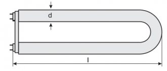
The inductor is an inductor coil wound on a ferromagnetic core with a large magnetic permeability. It is an integral part of electromagnetic switchgear equipment (EMPPA). At the stage of turning on the LDS, it, together with the starter, ensures heating of the cathodes and then creates a high-voltage pulse (up to 1000 V) to create a glow discharge in the flask due to its inherent electromotive force (EMF) self-induction.
It will be interesting➡ How to make a charger for a car battery with your own hands
After the starter is turned off, the inductor uses its inductive reactance to maintain the discharge current through the LDS at the level necessary for constant and stable ionization of the gas-mercury mixture used in the flask. The magnitude of the inductance is such that the resistance of the inductor for alternating current protects the electrode spirals from overheating and burnout.
You can check the serviceability of the fluorescent lamp inductor by measuring the resistance using an ohmmeter. It is part of the electrician's combined instrument.
If you check the choke of a fluorescent lamp with a multimeter, you can find either its working condition, in which the measured active resistance corresponds to its passport data, or you can encounter inconsistencies. After analyzing them, we can draw a conclusion about the nature of the detected defect. Short circuits are accompanied by an unpleasant odor and a change in the color of the protective insulation. If there is any external manifestation or detected deviation of the value of the measured resistance from its nominal value, the inductor must be replaced.
Checking the choke of a fluorescent lamp.
How to check a fluorescent lamp choke with a multimeter
The most wear-resistant element in the design of luminaires with fluorescent lamps is the inductor, the breakdown of which is quite rare. A malfunction of such an element can be represented by a break or winding burnout, or violations of interturn insulation in electrical wires.
Both faults can be detected by connecting a tester in the form of a multimeter to the choke terminals to measure resistance. The presence of infinite resistance indicates a break and burnout.
Starter and choke for fluorescent lamps
As a rule, burnout is accompanied by the appearance of an unpleasant odor emanating from the part that has become unusable.
Any verification processes described above are valid only in the case of using electromagnetic ballasts, since electronic ballasts exclude the presence of a starter in the circuit.
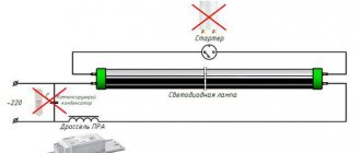
How does a fluorescent lamp work?
The voltage supplied to the spiral electrodes at the ends of the lamp is initially insufficient to ignite it. And here the throttle and starter come to the rescue.
After voltage appears in the starter, a discharge is formed inside, which heats the bimetallic electrode.
Due to heating, the shape of the electrode changes and it shorts out.
As a result, the current increases sharply and the electrodes become hot. The current is limited only by the resistance of the inductor itself.
The contacts of the starter gradually cool down and open. When opened, thanks to the choke, a self-induction effect occurs in the lamp, with the formation of a high-voltage pulse and an electrical discharge with a voltage of up to 1000V.
This discharge creates an ultraviolet glow from the mercury vapor that fills the flask. It affects the phosphor, and only thanks to it we can distinguish light in the spectrum that is familiar to us.
If this explanation is too abstruse for some, then here is one of the simplest and most understandable videos that explains in a language understandable to everyone how an LDS lamp works.
It turns out that the process of turning on a fluorescent fluorescent lamp itself is quite lengthy and takes 5 stages:
- supplying 220V from the socket and closing the starter contacts
- heating the electrode spirals
- starter contact opening
- supply of a high-voltage pulse from the inductor
- formation of a glow discharge in the flask and supporting it with an external voltage of 220V + bypassing the starter and excluding it from the circuit
As can be seen from the startup process, if the lamps malfunction, three elements may be to blame:
- the light bulb itself
- starter
- throttle
In this case, most often the light bulbs and starter are damaged - due to burnt out tungsten filaments and capacitors.
The easiest way to find out about this is by replacing the starter or light bulb. Moreover, they cost pennies. But how can you quickly find out about a throttle malfunction?
Reasons for burnout of fluorescent lamps
Often the LDS burns out, which makes it similar to a traditional incandescent lamp. When turned on, an arc of electricity is formed in the bulb, as a result of which the spiral-shaped tungsten electrodes become very hot. High temperature surges lead to destruction and burnout of the threads.
To extend the service life, a layer of active alkali metal is applied to the tungsten filament. The discharge between the electrodes is stabilized and the temperature decreases, thanks to which the thread lasts much longer.
Frequent switching on/off of the lamp entails the destruction of the protective layer, it simply falls off. The discharge passing through the bare filaments heats the spiral at weak points, resulting in burnout.
Break
The winding of the transformer or inductor may be broken. This means that its terminals do not have galvanic contact with each other. You can find out this using a tester. When taking measurements, do not touch both terminals with your fingers at once. Your body's resistance may distort the measurement results. Of course, for coils with a relatively small number of turns and a fairly thick winding wire, it is difficult to confuse the conductivity of the human body with the conductivity of the winding. But I have met coils with ohmic resistance of tens of kilo-ohms.
Properties, purpose and functions
Now let's look at what a throttle is from an electrical point of view. In short, this is an element that smoothes the current in the circuit, which is clearly visible in the graph. If we apply alternating current to it, we will see that the voltage on the coil increases gradually, with some delay. After the voltage is removed, current continues to flow in the circuit for some time. This happens because the coil's field continues to "push" electrons thanks to the stored energy. That is, the current in the inductor cannot appear and disappear instantly.
The current through the inductor increases smoothly and decreases just as smoothly. Looking at these graphs, it becomes clear that the inductor is an element that smoothes the current
This property is used when it is necessary to limit the current, but there are heating restrictions (it is advisable to avoid it). That is, the inductor is used as an inductive reactance that delays or smoothes out current surges. Like a resistor, an inductor has a certain resistance, which causes a voltage drop and limits the current. It just heats up a lot less. Therefore, it is often used as an inductive load.
The inductor has two properties that are also used in circuits.
- since it is a subtype of inductor, it can store charge;
- cuts off current at a certain frequency (the delayed frequency depends on the parameters of the coil).
In some devices (fluorescent lamps), a choke is installed specifically to accumulate charge. In all kinds of filters it is used to suppress unwanted frequencies.
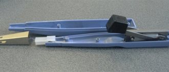
Starter
When voltage is applied, a glow discharge occurs in the starter. When heated, the bimetallic plates from which the starter electrodes are made close, as a result of which the current in the circuit increases significantly. The increased current heats up the electrodes of the fluorescent lamp, and they begin to emit electrons. At the same time, the starter electrodes cool down, the bimetallic plate bends and the circuit breaks. Thus, the starter is needed only at the moment of starting; it does not participate in further operation and its electrodes remain open.
It will be interesting➡ Tesla coil (Transformer) self-assembly on your own
In this case, due to self-induction, a short-term high-voltage pulse occurs at the choke, which leads to a gas discharge and ignition of the lamp. When the lamp is lit, the voltage on its electrodes is lower than the mains voltage by the amount of self-induction emf that occurs in the inductor when the lamp is ignited. Thus, the inductor prevents the current from increasing during the operating mode of the lamp. The disadvantages of this scheme are the long time it takes to turn on the lamp; as the inductor wears out, it begins to make a hum, and low efficiency at subzero temperatures.
Starters.
Types of Multimeters
There are currently two main types of this device on the market. This is an analog multimeter and a digital one.
Initially there were only pointer models
Analog
Analog testers appeared on the market earlier.
When using an analog multimeter, the measurement result is read from the arrow. She moves along the scale. It contains the following indicators:
- current;
- voltage;
- resistance.
Their design contains elements whose work is based on magnetism.
The accuracy of these devices is influenced by factors such as:
- magnetic fields (are there any in the measurement area);
- air humidity;
- temperature.
For your information . The main disadvantage of an analog multimeter is associated with the scale. If it is not depicted well, it may be difficult to read the device's readings. Then there will be a measurement error.
The advantages are their availability and simplicity. In addition, analog multimeters are inexpensive.
The highest accuracy of measurements with an analog multimeter is achieved using a special construction resistor. It is built into the device.
In most countries, the production of multimeters of this type has been discontinued.
Non-analog models are most common