Transformers became a part of human life with the beginning of electrification. Then they began to be used as DC voltage sources for various equipment, appliances, and household appliances.
The article provides information about the operating principle of these devices, their varieties, and the search for power. Tips will also be given on how to test a transformer with a multimeter.
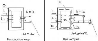
Operating principle and purpose
The main purpose of a transformer is to convert or reduce electrical voltage. Depending on the design and purpose, transformers change the current rating, voltage, or convert the pulse to the required value.
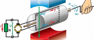
The operation of a transformer is based on the principle of the formation of a magnetic field during the interaction of a metal core and a constant voltage. When a voltage of 220 V is connected, the current moves through the primary winding of the transformer, forming a magnetic field. Next, the current enters the secondary winding, the number and pitch of which is much smaller. A strong resistance is created, which is smoothed out due to the influence of magnetic fluxes. Thus, in the secondary winding, the voltage is greatly underestimated, resulting in a lower number output voltage.
Checking household step-down devices
It is worth noting the moment of checking classic step-down transformers with a multimeter tester. They can be found in almost all power supplies that reduce the input voltage from 220 Volts to the output voltage of 5-30 Volts.
The first step is to check the primary winding, which is supplied with a voltage of 220 Volts. Signs of a primary winding malfunction:
- the slightest visibility of smoke;
- the smell of burning;
- crack.
In this case, the experiment should be stopped immediately.
If everything is normal, you can proceed to measurements on the secondary windings. You can touch them only with the tester contacts (probes). If the results obtained are less than the control ones by at least 20%, then the winding is faulty.
Unfortunately, such a current block can be tested only in cases where there is a completely similar and guaranteed working block, since it is from it that the control data will be collected. It should also be remembered that when working with indicators of the order of 10 ohms, some testers may distort the results.
Design
Regardless of the design and purpose of the transformer, its design is as simple as possible. These devices consist of:
- Steel or ferromagnetic core. Used to generate a magnetic field. Cores can be of various types. It all depends on the purpose of the device and the amount of current conversion.
- Winding. The device has at least 2 windings: primary and secondary. It is a copper or aluminum wire insulated with varnish. The winding is wound on a transformer with a given number of turns, pitch, and wire cross-section. It is the transformer winding that affects the input and output voltage parameters.
- Terminals and contacts. Necessary for connecting the device to the network and output circuit.
- Constructive additions. They can be protective housings, insulating and fastening elements, cooling radiators. All this is necessary to ensure reliable installation and protection from direct voltage.
The type and purpose of the voltage converter can be determined by its appearance. To do this, you need to know the main types of transformers.
How to calculate a power transformer using formulas in 5 steps
I present a simplified method that I have been using for several decades to create and test homemade transformer devices made from iron of an unknown brand in terms of load power.
Using it, I almost always managed to wind the circuit on the first try. Very rarely it was necessary to add or reduce a certain number of turns.
Stage No. 1. How does the power of a dry-type transformer affect the shape and cross-section of the magnetic circuit?
The calculation is based on the average efficiency ratio ŋ, as the ratio of the electrical power S2 converted in the secondary winding to the applied total power S1 in the primary.
Power losses in the secondary winding are estimated using a statistical table.
| Transformer power, watts | Efficiency ŋ |
| 15÷50 | 0,50÷0,80 |
| 50÷150 | 0,80÷0,90 |
| 150÷300 | 0,90÷0,93 |
| 300÷1000 | 0,93÷0,95 |
| >1000 | 0.95÷0,98 |
The electrical power of the device is determined by the product of the rated current flowing through the primary winding in amperes and the household wiring voltage in volts.
It is converted into magnetic energy flowing through the core, fully distributed in it depending on the shape of the flow distribution:
- for a ring figure of U-shaped plates, the cross-sectional area under the magnetic circuit coil is calculated as Qc=√S1;
- for a core made of Ш-shaped plates Qc=0.7√S1.
Stage No. 2. Features of calculating the transformation ratio and currents inside the windings
A power transformer is created to convert electrical energy from one voltage value to another, for example, U1=220 volts at the input and U2=24 V at the output.
The transformation ratio in the above example is written as the expression 220/24 or a fraction with the primary voltage value in the numerator and the secondary voltage in the denominator. It also allows you to determine the ratio of the number of turns between the windings.
At the first stage, we have already determined the electrical power of each winding. Using them and the voltage value, it is necessary to calculate the strength of the electric current I=S/U inside any coil.
Varieties
Depending on their purpose, transformers are used in various fields, not only in instrument making. They differ in the following types:
- Power. It is used as a step-down transformer at power plants, large organizations, and in the public power supply network. Several similar devices are used in the power supply circuit. Their task is to lower the voltage from the power plant to the consumer. Also, power transformers can operate on the reverse principle, as a step-up device. Such devices are necessary for transmitting electricity over long distances from power plants to consumers, significantly relieving the load on generators.
- Network. The most common in household appliances. The main task of these devices is to reduce the voltage from 220 to 36, 24, 12, 9 volts. Line transformers can be found in household appliances manufactured before 2000. Now these devices look much smaller and are rarely used.
- Pulse. They replaced network elements. The main difference in operation is the conversion of pulsed voltage, rather than direct current. This principle contributed to a reduction in size, the possibility of saving materials, the use of a transformer as a step-down device and protection against overloads.
- Current transformer. Used to measure current value. It is used in circuits between power transformers and a 380 volt output and electricity consumption meters. Also used as a protective device. The primary winding of this transformer is connected to the electricity supply circuit in 1 phase, providing protection against voltage drops as a result of failure of the power device.
There are also laboratory or autotransformers. Their only difference is the ability to adjust and switch the output voltage from one value to another.
What is the equipment?
How to check a transformer if we don’t know its design? Let's look at the principle of operation and types of simple equipment. Turns of copper wire of a certain cross-section are applied to the magnetic core so that leads remain for the supply winding and the secondary winding.
Energy is transferred to the secondary winding in a non-contact manner. At this point it becomes almost clear how to check the transformer. The usual inductance is measured in the same way with an ohmmeter. The turns form a resistance that can be measured. However, this method is applicable when the specified value is known. After all, the resistance can change up or down as a result of heating. This is called an interturn short circuit. Such a device will no longer produce the reference voltage and current. The ohmmeter will only show an open circuit or a complete short circuit. For additional diagnostics, use the same ohmmeter to check the short circuit to the housing. How to check a transformer without knowing the winding terminals? This is determined by the thickness of the outgoing wires. If the transformer is a step-down transformer, then the output conductors will be thicker than the input conductors. And accordingly, vice versa: the input wires of the booster are thicker. If two windings are output, then the thickness may be the same, this should be remembered. The surest way to look at the markings and find the technical characteristics of the equipment. Transformers are divided into the following groups:
- Down and up.
- Power ones often serve to reduce the supply voltage.
- Current transformers for supplying a constant amount of current to the consumer and maintaining it in a given range.
- Single and multiphase.
- Welding purposes.
- Pulse.
Depending on the purpose of the equipment, the principle of approach to the question of how to check the transformer windings also changes. Only small-sized devices can be dialed with a multimeter. Power machines already require a different approach to fault diagnosis.
Video: detailed description of the operating principle of a pulse transformer https://www.youtube.com/watch?time_continue=13&v=XYxKfYd8Elk
Examination
Checking the transformer for operability and output voltage must begin with a visual inspection. On the body of many modern and old-made elements, a schematic diagram is applied. It contains information about the input and output contacts, the number of turns of the primary and secondary windings, and the values of the output voltages. If this information is not available, you need to ring the transformer.
Many novice radio amateurs are faced with the problem of how to ring a pulse transformer with a multimeter. Further recommendations will be given using this particular device as an example.
Turn-to-turn short circuit
The most important test. It is prohibited to connect unknown transformers found somewhere without a short circuit test. The interturn short circuit cannot be determined using a multimeter. The reason for this lies in the breakdown of two adjacent windings and their connection to each other.
When testing the resistance, it will remain unchanged (if there is no break before the short circuit). Therefore, the transformer is checked visually. Any darkening, swelling, melting of insulation or carbon deposits on the paper can be considered a result of a short circuit. Melting and carbon deposits occurred due to heating of the winding under load. When the primary winding is shorted between turns, the current passes through fewer turns, which creates a load and heat. Short circuit can also be identified by the smell of burning.
If the external appearance of the device does not have any defects in the insulating coating, you can begin the next check.
Search for windings
This test is necessary if the element was not initially connected to the electrical circuit of the instrument or device. The primary winding of the transformer has a larger number of turns, since it is supplied with high voltage. This means that the resistance should be much greater. The input of the primary winding is always located at the top of the device, the secondary terminals at the bottom. To search you need:
- Set the multimeter to resistance measurement mode.
- Connect both control probes to two terminals of the transformer.
- Save the received values.
Next you need to find the outputs of the secondary coils. This is done according to the same principle. If there are more than 2 outputs, then it is necessary to measure each pair. The resulting values are also saved.
Now you need to verify the results. The leads with the highest resistance will indicate the input primary winding. The remaining pairs will be output contacts.
Integrity
Determining integrity is necessary to find out if there is an open circuit in the transformer circuit. The previous check helped clarify which contacts are incoming and outgoing. Now we need to determine their integrity. To do this you need:
- Set the multimeter to dialing mode with a sound alert.
- Connect 2 control probes to the input contacts of the transformer.
- An audible warning will indicate the integrity of the wire.
In the same way, you need to check the remaining output contacts. Modern step-down devices for household use have one caveat. A thermal resistor is built into its primary winding circuit. It's easy to find. It is soldered between the terminal and the beginning of the winding and hidden under the insulation. If testing at the input shows a break, you should carefully open the insulating layer and find the resistor. Next, take another measurement, but only the wire itself, behind the resistor. If the test was successful, then the thermal element needs to be replaced.
A thermal resistor is needed to shut down the circuit during overheating. It can fail due to high load without passing high voltage into the circuit.
Determining the magnitude of the incoming voltage
This test will help you find out whether the element can be operated from a household electrical network or whether it is designed for voltages of other values. To determine the current value it is necessary:
- Connect one contact of the incandescent lamp to the TP input terminal.
- The second contact is to a 220 V voltage source.
- Terminal “2” from TP to “2” terminal of the voltage source.
If the lamp does not light up, this indicates that the transformer is designed to operate on a 220-volt network. The burning of a lamp of any incandescence will indicate operation from currents of other magnitudes.
Output voltage measurement
After carrying out all the tests for the integrity of the pulse transformer, you can proceed to connecting it to electrical voltage and measuring the output voltage. To do this you need:
- Connect 220 volts to the found input connectors.
- Measure the voltage at the input terminals in pairs.
- Save the results obtained.
If the transformer body has markings for the magnitude of the output voltages, then when measuring they should be 5–20% higher. This is done to reserve power for subsequent connection to the diode bridge.
If there is no marking, you need to do the following:
- Connect the red control probe to the “1” output terminal.
- Connect the black probe one by one to the other terminals.
- If the measurement gave results from 9 to 24–36 volts, then these contacts must be noted.
The test is considered successful if all connectors show certain values.
Important! The transformer outputs have alternating voltage. Do not take measurements by touching bare contacts with your hands.
Help me figure out the transformer
As I understand it, there is a possibility of 220V slipping into the 110V circuit - and this will burn the device designed for 110V. Maybe you can install some kind of protection such as a capacitor-thyristor-varistor (I don’t remember more details). Transik is good because it is small and fits perfectly into the housing of the XT power supply, you can build a good unit. Buying a large transformer is not a problem, but the dimensions are useless.
The danger of using an autotransformer does not lie in some possibility of “220 V slipping into the 110 V circuit.” This “probability” exists for all transformers and not only transformers.
The danger lies in the presence of a galvanic connection between the primary network and the load.
Let's explain with an example:
Let's say you have two step-down transformers, which “make” 220 V, for example, an absolutely safe voltage of 6 Volts.
But one transformer is “just” a transformer, with isolated primary and secondary windings, and the second is an autotransformer, in which the secondary winding is part of the primary.
The first transformer (with high-quality insulation between the windings) is absolutely safe.
We can touch any of the terminals of the secondary winding, grasp both terminals of the secondary winding and, finally, simultaneously touch the terminals of the secondary winding, etc. “earth”, in the form of a heating radiator, metal water pipe, gas pipeline, etc. (This does not mean at all that this should be done. The most “advanced” ones fill the bathtub with water, lower their unfortunate body into it, turn on the electric razor and use it for its intended purpose. In my opinion, this is complete p....., you have to be a complete idiot to do this do)
If we receive 6 volts from the autotransformer, an attempt to touch between any wire of the secondary winding and the ground can lead to death. I would like to draw your attention to the fact that the serviceability/failure of the transformer has nothing to do with it!
Therefore, most accidents with autotransformers are not associated with contact with the output voltage of this device, but with contact between the ground and any of its terminals.
Don't believe those who claim that a fuse will make the autotransformer safer.
Only from a fire safety point of view, from the point of view of electrical safety - no way - the lethal value of the current through a person is much less than that necessary for the fuse to burn out.
Modified March 17, 2008 by MMS user
Power determination
Next, we will consider the question of how to find out the power of a transformer. To do this, you will need to measure the width of its core. If the TR has a “W” type core, then you will have to measure the thickness of the central plates. For example, the thickness of the plates is 2 cm, and the width of the central set is 1.7 cm. It is necessary to multiply these values, obtaining the number 3.4 sq./cm. Next, you will need an averaging factor for transformers equal to 1.3. 3.4 divided by 1.3 = 2.6 sq/cm. This value determines the power of the TR equal to 7 W.
Many people wonder how to determine the power of a transformer with a multimeter. It is not possible to test a household element in this way.
Adviсe
Checking the functionality of transformers is important before connecting or repairing a device. When working, you must observe the following rules:
- Carefully study the markings and diagram on the case.
- If there is no diagram on the case, direct connection is prohibited.
- It is prohibited to connect an unknown TR to the network without checking for a short circuit.
- Any measurements under voltage are carried out without contact with the terminals.
- Without desoldering the device from the circuit, it will not be possible to measure the output resistance.
- When working, you must strictly follow safety precautions.
Transformers, especially unknown ones, can cause electrical short circuits and cause a fire.