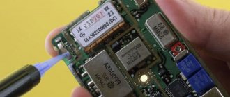
Kharchenko antenna for digital TV
In the 60s of the last century, Kharchenko designed an antenna that made up a double square of wire. Open corners connect the squares to each other. In the same place they connect to the television cable. In turn, a grid made of a material that can conduct current is installed on the back of the structure. In common parlance, this design has other names. It is often called:
- Kharchenko zigzag antenna;
- eight;
- butterfly;
- biquad TV antenna.
Currently, the Kharchenko antenna is successfully used not only for analog television, but also for digital television. This is due to the active transition of television to a new format – digital. It is conducted at UHF frequencies on channels 21-69 using the multiplex method. And therefore the design must be suitable. Since not all TVs are equipped with a built-in antenna, savvy owners make homemade Kharchenko antennas for digital TV, they are also called homemade ones. Such devices work no worse than those purchased on the market.
Kharchenko antenna for digital TV.
Indeed, such a device has advantages that are difficult to refute:
- assembly of such a structure requires a minimum of parts and skills;
- can be assembled even by a middle school student;
- installation takes about half an hour;
- budget;
- trouble-free operation of the device.
Next, we will talk in detail about installation at home. If you still don’t know what this device looks like, it is recommended to view the drawing of the Kharchenko TV antenna in advance on the Internet, simply by opening the pictures.
Making your own antenna.
Recommendations for use
The Kharchenko antenna has been actively used in households for more than one year, therefore, in order to ensure the longevity of its operation, it is recommended to periodically look after and care for it.
There are a number of recommendations
Here are some simple tips for long-term operation of the device:
- The connection between the cable and the antenna frame can be protected from external influences by wrapping it with regular electrical tape. However, this method is not permanent. It would be better to fill everything with glue.
- For the housing, some people use regular bottle caps or plastic jar caps. Recesses are made in the right places for normal cable exit. After which, everything is filled with a special sealing compound.
- When using an amplifier for a Kharchenko antenna for digital TV, the second square is not necessary.
- Also, for additional reinforcement, a double biquad is constructed. Everything is mounted in the same way as the regular version, but instead of the corners there are additional squares. As a rule, there are an even number of them. Their calculation is not necessary, because they must be similar in size to the main biquadrat.
That’s it, Kharchenko’s DIY television antenna is ready for using digital TV.
Evolution
The antenna, invented by Kharchenko, is a double square made of thick copper wire. The squares are connected to each other with open corners, and at this point the television cable is connected to them. To improve directionality, a grille made of conductive material is installed at the rear. The perimeter of each square is equal to the wavelength to which the reception is tuned. The diameter of the wire for 1-5 television channels should be about 12 cm. Because of this, for radio communications and meter range television (1-12 channels) it turns out to be very cumbersome.
To facilitate the design, a gasket with three wires of a smaller cross-section was used, but it still had a lot of weight and dimensions. The zigzag antenna created by Kharchenko received a second life when broadcasting appeared in the UHF range. Everyone remembers rhombuses, circles, triangles and other homemade figures as a TV antenna for receiving decimeter waves, which hung on many people’s balconies and outside their windows. They were one of the signs of that time.
In 2001, Professor Trevor Marshall (USA) proposed using this design in Bluetooth and WiFi networks.
Decimeter version
A design feature of the Kharchenko antenna is a fixed ratio between the perimeter of each of its two squares and the length of the received waves (they must be equal). To obtain the required induced field strength, it is also important to select the correct diameter of the frame wire. Since broadcasting was previously focused on the meter range, receiving such a signal would require a wire with a diameter of about 12 cm.
In this case, the zigzag antenna would be too bulky and inconvenient to use, and its dimensions would not allow it to be used at home. Kharchenko’s zigzag antennas experienced their second birth at the time of the advent of broadcasting in the decimeter bands. A zigzag antenna designed to receive a UHF signal must have fixed dimensions, which will be discussed in the following sections.
Related material: How to make an antenna for 4G.
The characteristic impedance for which such home-made structures are calculated is usually about 50 Ohms. This indicator, however, agrees well with a typical coaxial line with a corresponding parameter of 50 (75) Ohms. To expand the bandwidth of the television signal, such an antenna was made not from a simple wire, but from a flat copper or aluminum bus, the individual parts of which were connected into a biquadrate using pre-selected aluminum rivets.
At the junctions of the copper strips, the UHF antenna was additionally soldered; in this case, the distance between the rivets was taken as its length. In cases where, in order to obtain reliable reception, it was necessary to use a standard antenna amplifier, the developers did without the second square (one was enough for reliable reception).
Decimeter version of the antenna.
Execution in the DVB-T2 standard
Digital broadcasting, designated by the “dvb t2” standard, is carried out, as is known, at UHF frequencies corresponding to TV channels from 21 to 69, using the “multiplex” format. In many Russian cities, local television stations are gradually switching to the dvb TV broadcast format, which is causing some interest in ensuring its reliable reception.
In this regard, the user must know that a homemade design for T2 must have the same dimensions as a classic antenna for UHF digital broadcasting. Modern television receivers, which include an antenna for a digital signal, can weaken it if the transmitting station is close.
In special situations, when the transmitter for the T2 band is very close, when using the old frame design, you will either have to completely remove the second square (or screen), or choose a less sensitive amplifier.
The following solutions can be chosen as options for manufacturing a dcv structure:
- Make a completely new receiver for t2 with your own hands;
- Try to build a combined antenna containing an element in the form of a circle made of wire 55.5 cm long (see photo below);
- With its help it will be possible to receive all known formats (including 3g mobile communications).
It will be interesting➡ How to check the thyristor for performance?
In the case when you need to make a structure for receiving Internet signals, including Bluetooth, WiFi (3g, 4g) or mobile communication channels operating on ultra-short waves, the dimensions of such an antenna will be very miniature.
Kharchenko antenna made of two circles.
Due to the high frequency, the dimensions of the antenna for 3g will be limited to a length of 10 centimeters, and all possible varieties of a homemade product can be assembled using the same drawing. Significant differences regarding all possible versions of a miniature antenna (for Bluetooth or for a cell phone) will appear only in the dimensions of the receiving structure itself. The calculation procedure in this case is determined by the method of using a specific network resource (these methods are widely represented on the network for both T2 and other TV signal formats).
Improving WiFi and Bluetooth quality
It is known that the WiFi signal is transmitted, like other types of terrestrial communications, over a radio channel, which allows the use of an antenna design to improve the reception of a router or similar devices. According to a number of craftsmen from among the developers of 3g antennas, if in the design discussed above a parabolic dish is taken as a screen, the gain at WiFi frequencies can be increased to 31 dB.
Such a screen can be made from a tin can bent in a certain way. When making a reflector for 3g or WiFi, the curvature of its surface is usually selected experimentally. To do this, a program must be installed on the transmitting/receiving device (router, for example) that can record the level of the signal entering the device. Using such a program, it will be possible, by changing the curvature of the surface of a homemade screen, to monitor all changes in the gain (in real time).
Kharchenko antenna for different types of signals.
Improving Internet connection speed with Kharchenko antenna
It was previously mentioned that the described antenna is capable of receiving signals from mobile operators, so those who want to improve the quality and speed of the mobile Internet are also recommended to make a similar device. It will be especially useful when using wireless routers when you need to connect to a network outside the city, in nature, or in the country. That is, in situations where the user is in an area of poor reception, away from radio towers, telephone exchanges and a good signal.
HQClear TV antenna: the whole truth about divorce, real customer reviews
Calculation
There are no fundamental differences between homemade antennas for television and mobile networks, so the only nuance separating the equipment for the receiver and the router will be the size. The amplifier for routers will be slightly larger than the palm of your hand, since the frequency of mobile Internet waves ranges from 1.9 to 2.1 GHz. The exact parameters depend on the operator, but given the final dimensions of the amplifier, the differences are insignificant. You can clarify the correct indicators by calling the contact center of the cellular company or visiting the provider’s office.
Assembly
After making the calculations (manually or using an online calculator), you should proceed to assembling the antenna for 3G or 4G modems. Users will need:
- bend the wire in the form of two rhombuses;
- solder the edges and solder the cable to it;
- add a reflector to enhance reception power;
- connect the finished equipment to the router.
From the above instructions it is clear that nothing unexpected or new is expected in the manufacture of a smaller version. The main thing is to make accurate calculations and reliably solder the parts to each other.
Connection
The most difficult stage of amplifier manufacturing is connection. Most modern routers do not have a ready-made connector for the antenna cable, so you will have to connect it directly. For this you will need:
- disassemble the router or cell phone;
- disable the sensor responsible for receiving the signal and connecting to the network;
- connect a manufactured amplifier in its place.
The described actions can damage the equipment and will invalidate the factory warranty, so before making changes it is worth assessing the consequences of the actions taken in advance.
Kharchenko antenna for modem
Currently, many users are looking to increase the speed of their mobile Internet. This problem is especially acute for those who live at a considerable distance from the base station, using the Internet at very low speeds. In such situations, the best way out is a Kharchenko antenna for a 3g modem with your own hands, which is quite easy to make at home. This frame structure has been known as a UHF antenna since the 60s of the last century. It has a zigzag frame configuration which makes the device very efficient.
The system consists of two square elements. In order to calculate the antenna for a 3g modem at a frequency of 2100 MHz, the size of each side of the square must be 53 mm. The entire design is made in the form of an interlocking structure, which includes two diamond-shaped figures with internal angles of 1200. This is done in order to reduce the internal resistance of the device. The diamonds are connected to each other by soldering. The high-frequency cable is also soldered here.
How to make a Kharchenko antenna with your own hands.
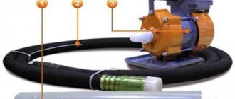
To increase efficiency, the device can be used in conjunction with a reflector. Usually this part is a metal plate, and the most suitable material for its manufacture is foil PCB. In this case, the antenna involves determining the distance between the receiving device and the reflector. After calculations and procurement of materials, a Kharchenko antenna for the modem can be made with your own hands.
The parts are connected to each other using hot-melt adhesive. You can fix the required distance between elements using any object with the most suitable dimensions. Then the antenna is connected to the device. Since modems do not have connectors for connecting external antennas, they are simply wrapped with wire, which is then connected through a cable to the receiving device. If necessary, a Kharchenko antenna for a 4g modem can be made using the same scheme.
Interesting read: How to solder aluminum at home.
Upon completion of assembly, at the opposite end of the cable that will connect to the modem, you need to assemble a so-called matching device, designed specifically for such devices. For this purpose, copper foil is used, the same as in printed circuit boards. The calculation of the antenna for the 4g modem is the same as in the previous version.
If there is a connector for an external antenna, the cable is connected using a special adapter. After all connections, the antenna for the modem is considered ready for use. Setting up signal reception for 4g is done experimentally by slowly rotating the structure around its axis until the clearest signal is obtained. The quality of the signal is determined by the number of lines on the icon displayed on the computer or mobile phone.
Optimal dimensions of the Kharchenko antenna.
Connection and setup
Of course, you will need to somehow connect the finished device to the modem. Please note that everything you do with warranty equipment is done at your own peril and risk! The editors do not bear any responsibility for this. First, remove the top cover of the modem. This must be done carefully, preferably with a thin screwdriver or scalpel. Starting at one end, near the USB connector, then slowly pry the cap until it opens on one side. Then repeat the same procedure, but from the other end. Removing the cover, you will see two small connectors sealed with protective paper.
If we place the modem with the USB port down, then we need the left connector. Don't even touch the right one! Now you have two options: either buy a branded peakdale (adapter), or make your own. We chose the second option, taking the antenna adapter from a small burnt TV tuner and modifying it slightly by removing the inner plastic ring. But if you don’t have such a thing, then it’s better to buy a branded one.
Do-it-yourself television antenna for a digital signal.
Then you need to connect it to the wire. The wire should be used RG-6U, as it is the most suitable in terms of characteristic impedance. The shorter the length of the wire itself, the less signal loss there will be. In this case, we put a regular TV plug on one end of the wire, which is ideal for our homemade peakdale. The second part had a screw-on part of the high-frequency connector for connecting to the antenna. After that we connect everything together. The branded Peakdale has a special attachment to the modem, but we used a paper clip and two rubber bands. Despite the fact that the design looks rather flimsy, it has been in our editorial office for four months now.
It will be interesting➡ We assemble a step-up transformer with our own hands
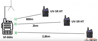
Next, you should hang the antenna on the street. We used a mast from an active television antenna and its mount. After this, you need to connect the cable to the modem and put everything together. Next, we climb out onto the ledge (be careful not to fall down!) and set up the antenna for the access point. This is done simply: you slowly turn the antenna in all directions and monitor the signal level. Having found the point where the signal will be maximum, you fix the antenna as tightly as possible and forget about its existence. We managed to achieve a signal of 15 dB where the modem without an antenna received 3-4, sometimes 5 dB. Practice has shown that for radio amateurs such an antenna achieved a range of 2.5 km.
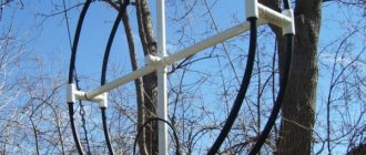
Design and manufacture of the Kharchenko antenna
We are probably used to seeing the same thing in the pictures. Here is how it is proposed to design a Kharchenko antenna (the VashTekhnik portal keeps pace):
- It is necessary to find out the wave frequency and polarization. The Kharchenko antenna is linear.
- The copper antenna is formed by two squares. Both stand on the corners, one touching. For horizontal polarization, the figure eight stands upright; vertical - lies on its side.
- The side of a square is found by the formula: wavelength divided by four.
- You can imagine the design if you imagine an oval, pulled together in the center across the larger side. The sides do not touch, although they are close to each other.
- The power cable is connected to the points where the sides approach. It is necessary to block one direction of the diagram - place a flat copper screen at a distance of 0.175 operating wavelengths, and place it on the braid of the power cable. The reflector is made of a metal plate. In the old days, they used textolite boards covered with copper.
Completed brief design of the Kharchenko antenna. The details become full of problems: the task is to strengthen the emitter. For the communication range - wire ropes; television - a wooden frame is often used, studded with crossbars (resembling a cross); in the microwave range, modem owners support the emitter with a pair of plastic stands that pierce the screen.
Interesting read: What is a Hall sensor.
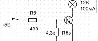
Firstly, with a square side of a quarter wavelength, we see the lower frequency of the range. The author did not comprehend the upper one, but we can calculate it indirectly, using skillful considerations (below in the text is a figure describing the design). Shown: the frame consists of three conductors (more than one). Individually sized cuts, the height of the average square is equal to 0.28 wavelengths of the lower frequency. We don’t see anything complicated, multiply the reference value by cos 45, find out: the side size is 0.198 wavelengths. According to Kharchenko, at the announced frequency, the side of the frame is a quarter of the wavelength. We conclude: speech affects the larger square, the side of the smaller one is approximately 0.14 wavelengths.
Continuing the analogy, we divide the great by the small, we get: the range coefficient is 1.8. Kharchenko K.P. mentions in passing: the radiation pattern is maintained at a ratio of maximum and minimum frequencies of 2 - 2.5. The book provides a drawing of an antenna for catching broadcasts of two ranges 50 - 100 and 174 - 230 MHz. You can, following the beaten path, imagine the possibilities provided by the product in terms of channel closure. That is why, when making a Kharchenko antenna for WiFi according to the scheme indicated above, the lowest frequency used should be taken as a basis. Otherwise, part of the signal will go beyond the operating limit of the antenna. The fact is directly hushed up; the conclusion follows from the author’s presentation of Kharchenko’s material. Although the engineer immediately says that geometric errors are not important, the operating range of the antenna is very wide.
Design of antenna parameters.
There are three frames, the distance between the extreme ones (along the perpendicular cross-section of the wires) is 0.033 of the maximum wavelength (minimum frequency). We believe that readers will calculate the dimensions themselves (and perhaps find that they were mistaken a little higher), but that is not the point. These three frames are assembled on a mast and have a radiation pattern that also has a vertical component. Increasing the frequency reduces the parasitic effect. Let's add to this that in the upper part of the range a current distribution is formed in which the Kharchenko antenna will avoid matching, while in the rest of the range a transformer will be required. The device can be made from a length of 100-ohm coaxial cable... and here the author got carried away.
It is known that if RK 1 is used for power supply, the transformer is made from RK 3. And vice versa, when powering RK 3, the transformer is made from RK 1. In our opinion, the material is presented in a non-structural way... In the first case, we remove the insulation and braiding of RK 1 along a segment of the length of the transformer, We replace the sounded household RK 3, from which the central core was pulled out. In the second case, on the contrary, we remove the core of the supply cable RK 3 to the length of the transformer, replace the core RK 1.
How to make an antenna with your own hands.
The geometric dimensions have been indicated, we list them together:
- The height of the square standing on the corner is 0.28 of the maximum wavelength, along the middle contour of the three.
- The distance between the outer frames across the direction of the wire is 0.033 of the maximum wavelength.
- The length of the matching line with a characteristic impedance of 100 Ohms is 0.052 or 0.139 of the maximum wavelength.
By the way, it is not at all necessary that the antenna consist of squares. The characteristics of the device do not depend greatly on the apex angle. The height of the figure eight (standing upright) must be maintained. Therefore, if the angle changes from 90 to 120 degrees, the sides lengthen. Proportional. Specific values can be calculated. Now readers know how to make a Kharchenko antenna with your own hands. And here's another thing. I have seen, while surfing the net, structures where the emitter curved around the screen. In this way, the main lobe of the radiation pattern supposedly expands. In practice, in this case it is easier to use a patch. Here the platforms can be directed in different directions.
Kharchenko antenna diagram for 3G.
Theoretical part
indeed, if we err slightly against the truth and use the fact that the antenna within one range is indeed very broadband, then it works quite acceptably with a 50 or 75 ohm cable without special matching and tuning measures. But, if we look at everything in detail, it turns out that the antenna resistance very much depends on the shape of the frames and, of course, on their size. For example, the graph on the right shows the biquad impedance curves depending on the physical size of the frames. And we already know that the antenna is very broadband and can successfully operate not only at the resonant frequency but also near it. Therefore, biquadrat antennas are sometimes called not a resonant antenna, but a band antenna. Angle “a” is the physical angle between the vertical and the frame elements.
It will be interesting➡ How to do HDMI pinout
In this particular case, the angle is 45 degrees, that is, the shape of the frames are perfect squares. On the graphs you can see that if the perimeter of the frames exactly corresponds to the wavelength (the side of the square is equal to 0.25 of the perimeter), their impedance lies in the range of 50-60 ohms. If the side of the square is increased to 0.33, then the resistance increases to 120 ohms. It is calculated that the maximum gain of the biquad and the best directional properties will be when the length of the side of the square is equal to 0.375. Of course, the resistance increases many times over - up to 600-700 ohms, which is of course a lot even for our idea. The second graph, on the left, shows the dependence of resistance on angle “a”. If we consider the resistance graph with a square side length equal to 0.25 perimeter - directly resonant, but with an angle of the side to the vertical equal to 60 degrees, then we will find that the resistance of the biquadrat, or Kharchenko antenna, will not be 50 ohms, but 100!
Large Kharchenko antenna.
Thus, we obtain an antenna with a circular radiation pattern with minimal difficulties in manufacturing and configuration. If one antenna is rotated 90 degrees not only in the horizontal, but also in the vertical plane, then we get an antenna with circular polarization and a circular radiation pattern. The simplest calculation will show you that to form an angle of 60 degrees between the vertical and the sides of the rhombus (with a perimeter equal to the wavelength, in our case 2000 mm), the height of the biquadrat should be 1000 mm, and the distance between the extreme points 866 mm.
The resistance of one such “biquadratin” will be 100 ohms. To obtain a circular radiation pattern, two biquads are placed at an angle of 90 degrees to each other and connected to each other using a quarter-wave transformer-phase shifter made of a cable with a resistance of 50 Ohms. Taking into account the shortening factor (for RG-58), this is a segment of 34.2 cm. You have probably already noticed my love for copper wire and sewer pipes? So it’s true, I don’t know a better material for modeling and practical manufacturing of VHF antennas.
Although, of course, everything described below can be replaced with your own structure made of wood, for example, or other available insulating material, and the wires with pipes or strips of tin or galvanized steel. Don't forget that there is an easy way to evaluate the quality of the antenna dielectric material.
If I had not been a radio engineer in my youth, I would simply repeat the almost universally repeated phrase that the gain of the Kharchenko antenna is 6-8 dB. But since I understand the issue, I can say that the gain of one Kharchenko antenna (when it is 50 ohm) will not be more than 4 dB. In our case, when the resistance of one antenna is higher and the efficiency is better, maybe a little more. There will be no gain in gain from two antennas forming a circular radiation pattern, but we can safely say that in this antenna, let’s call it conventionally “two diamonds” (in appearance), the gain will be at least 4 dB in all directions.
So, let's move on to the design. Due to the fact that plastic tube sticks from McDonald's balloons are no longer suitable, the idea came to mind to use plastic sticks from children's skis, which the eldest grandson has already outgrown, and the youngest no longer wants red. The length and diameter are suitable, only the color let us down...