Voltage surges can damage electrical household appliances. To prevent this from happening, special devices are used - voltage stabilizers. They protect the electrical network from interference, unstable power supply and provide devices with the necessary 220 V for operation. Stabilizers are especially needed in a country house or cottage, since it is outside urban conditions that an unstable network is most often found. Stabilizers can be used both for simple household appliances (TV, refrigerator) and for devices with increased power.
Types of stabilizers
Just one stabilizer can protect electrical appliances from overload, voltage surges, and short circuits
. All devices that stabilize voltage can be divided into several categories:
- electromechanical;
- relay;
- magnetoelectric;
- pulse converters.
Switching of transformer windings in an electromechanical stabilizer is carried out using a motor. The sliding block adjusts the supplied voltage. The disadvantage of the system is its large dimensions. Relay and magnetoelectric devices are also large-sized. This is due to the presence of a large transformer for voltage equalization.
If you need a compact device, it is better to choose a pulse device. It costs more because the design contains special inverters.
The choice of a specific model directly depends on the installation location and financial capabilities of the user.
Necessary materials
To connect, you will need the stabilizer itself. It must be selected in advance, taking into account which device will be connected to it. The following materials are also needed:
- Three-core cable VVG. Its cross-section must coincide with the cross-section of the input cable on the switch or input circuit breaker.
- Three-position switch to activate the stabilizer. It has 3 states - the first consumer is on, the second consumer is on and off. Instead, you can use a regular modular switch, but in this case, when disconnecting from the stabilizer, the entire room will be de-energized each time.
- PUGV wires of different colors.
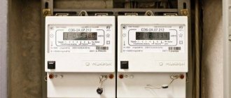
The stabilizer must be mounted before the energy meter. Any other connection is prohibited. This is due to the fact that the stabilizer has its own idle speed and consumes electricity. It must be taken into account when paying bills.
It is also recommended to install an RCD or differential circuit breaker in the circuit before connecting the stabilizer.
Choosing an installation location
The voltage stabilizer must be installed away from flammable and combustible liquids.
You must select in advance the location where the stabilizer will be installed. The dimensions of the device are determined by its power output. Small stabilizers can be installed next to the equipment on the table. Large models require permanent installation. The installation location can be a floor, a wall or a pre-equipped niche.
Operating transformers heat up, which is why it is necessary to install a heat removal system. For this reason, the stabilizer should be installed in a place where ventilation holes will be accessible. Then the necessary air exchange will be created inside.
The installation location must be dust-free, free from humid air, and away from flammable and combustible liquids. High temperatures, dust, and moisture can damage the stabilizer. The optimal location is to install it next to the distribution box at the entrance to the meter.
We connect the voltage stabilizer to the network
A voltage stabilizer is special electrical equipment whose task is to improve the quality of the power supply, in particular to ensure a stable value of the output voltage, making it independent of fluctuations in the input voltage. In order for your own equipment to work efficiently and safely, you need to competently approach the issue of choosing this unit (all parameters are taken into account, including load and others). Choosing a stabilizer is only part of the question; it should also be connected correctly, which is necessary to protect equipment from voltage sags, interference and other emergency situations in the network. In this article we will look at the question of how to connect a voltage stabilizer with your own hands.
Connection in the distribution panel
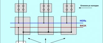
After the machine, a three-position switch must be installed in the panel. In position 1, when the lever is raised up, the voltage is supplied directly from the network, without using a voltage stabilizer. This mode is used if the voltage regulator is broken or inspection work is being carried out.
In position 2, with the lever pointing down, electricity flows through the stabilizer. In the zero position, all devices are disconnected from both the stabilizer and the power supply.
Regulation I
Regulation II
Position 0
Two VVG cables are laid from the panel to the selected installation location. For convenience, they need to be marked: input to the stabilizer and output. Part of the insulation is stripped from the cores and connected to the electrical panel. The phase from the input of the stabilizer goes to the output terminal of the difavtomat. The phase from the output goes to pin 2 on the three-position switch. Zeros and grounds from both wires are connected to the corresponding buses.
Afterwards, the phase from the machine goes to a three-position switch. The PUGV mounting wire must be stripped of the insulating layer, terminated with a lug and connected from the circuit breaker phase to the 4th terminal of the switch.
The last step is to power the machine from terminal 1 of the three-position device. This is also done with a flexible installation cable.
Laying VVGnG-Ls cables
Cable markings
Connecting the phase from the stabilizer to the input circuit breaker
Connecting the phase to contact No. 2
Connecting zero and ground
Inserting the conductor of the phase output of the input machine onto terminal No. 4
Power supply of all machines from terminal No. 1 of the three-position switch
Clamping of cables (input and output) under terminals
Before connecting, be sure to check the correspondence of the contacts in the documentation. They may differ for different models.
Connecting single-phase consumers
The most rational approach to power supply to a private home would be to select a separate group from the total number of consumers, which requires stable voltage parameters. Typically, increased stability is required for televisions, refrigerators, office equipment and communications equipment. Other household appliances, especially those with heating elements, do not necessarily need to be connected to the stabilizer. Electric kettles and electric boilers will still work, since voltage drops for them do not play a decisive role in the performance of basic functions.
In the home panel, after the electric meter, protective equipment is installed - a differential circuit breaker or an RCD with a circuit breaker. From them, phase and zero are supplied by separate cables to the input terminals of the stabilizer. The device body is also connected with a separate wire to the PE bus installed in the panel. From the output terminals of the stabilizer, a phase and a working zero are supplied to the consumer. The protective zero is connected to the PE bus.
The next option involves connecting several groups of consumers to the stabilizer at once. In the simplified circuit, protective grounding is not used, and the stabilizer is connected through one terminal of the working zero. The operation of the scheme is best viewed using the example of three consumer groups.
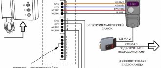
Connecting wires
Phase - white wire, zero - blue, ground - yellow-green
To connect, you need to remove the protective cover on the stabilizer. The input and output cables are threaded through the hole and clamped using terminals. The phase of the input cable must be connected to the input of the Lin stabilizer. Zero – to terminal N. Ground to the corresponding terminal. If there is no ground, the core is screwed under the screw of the device body.
After applying voltage from the distribution box, you need to supply stabilized power back to the panel. To do this, you need to connect via the output cable from the stabilizer. Phase - to the Lout output, zero - to N, ground - to the same place where the grounding conductor from the input cable is connected.
The last step is a visual inspection of the correct connection and testing of the system.
Features of connecting the stabilizer to a three-phase network
Three-phase stabilizers for each block have their own terminal blocks. When they are connected to the network, there must be a uniform distribution of single-phase consumers. This can be achieved by connecting to different blocks on the stabilizer.
Typically, such circuits can be connected in manufacturing and industrial enterprises. This is due to the high cost of the device itself.
Scheme No. 1
Scheme No. 2
In domestic conditions, three-phase power consumers are connected through a single-phase device.
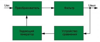
Operating principle and design features of stabilizers
The principle of operation of stabilizing devices is as follows: the incoming electrical energy is transformed, and a voltage with the necessary parameters appears at the output, powering all connected household appliances and equipment.
During the transformation process, the stabilizer can operate in amplitude reduction, simple transmission, or voltage increase modes. In the second case, electricity is converted without changing the amplitude. In this case, wasteful energy is wasted, causing the equipment to heat up. In this regard, some models have a bypass function. A switch is placed on the housings of such devices, with the help of which the entire power part of the equipment is switched off. The reverse action turns on all devices.
All stabilizers differ in design features and technical characteristics. First of all, this is the power passed through them, the minimum and maximum values of the input values and other additional functions. This way, you can choose the model that best suits the consumer's specific conditions. Supply circuits and loads can be connected to stabilizers in different ways, depending on the design and purpose of these devices.
Each model has terminal pins that allow you to change the connection configuration. If there is a protective zero in the circuit, the PE conductor is connected to the middle terminal. Working neutral conductors are connected to adjacent terminals, and the outer terminals are used for switching phase wires. Input circuits are connected on the left side, and output circuits on the right.
In the absence of a protective zero, the terminal block circuit is greatly simplified. The working zero is combined inside the housing, and the circuits are connected to three contacts: input phase, common working zero, output phase. The simplest low-power models are equipped with a cord and plug, and consumers are connected directly to the socket installed on the stabilizer body. You should be especially careful when connecting wires in three-phase voltage stabilizers.
Basic mistakes
Connecting through a simple machine, not a three-position one.
The most common connection errors include:
- Wrong choice of location. You can tell that the location is poorly chosen by the device overheating, shutting down, or the appearance of erroneous information on the display.
- Using a regular machine, not a three-position one. Using a classic circuit breaker will not protect the device from damage. The voltage stabilizer must switch from normal mode to “transit” mode with a certain sequence. First, the machines on the panel are turned off, then the switch is switched to “transit” mode. Only after this the machines are used again. If you do not follow the given sequence, switching will occur under load, causing the equipment to fail. When using a three-position switch, there is no need to memorize the algorithm.
- Incorrect connection of the voltage stabilizer for the home; the connection diagram is chosen incorrectly.
Lack of lugs on stranded wires - Wrong choice of connection cable cross-section. A thinner wire is not able to withstand the entire load passing through it, which leads to damage to the devices.
- Failure to use tips. All wires must be crimped, even when connecting devices with low current.
- Problems with machines in the panel. Even if the device is properly connected and in good working order, knockouts may occur. It can be caused by low supply voltage (for example, 150-160 V when the required 220-230 V).
When installing the device, you need to take into account all the nuances and not make the listed mistakes.
Three-phase stabilizer connection diagram
Yeah, I understand...
Three-phase Resanta doesn't like the three UZMs in front of her. She doesn't understand them and that's all. The fact is that the voltage relays turn on after a short delay. The UZM makes sure that the city voltage is stable and, after a minute delay, turns on.
But three relays may not turn on simultaneously and because of this the stabilizer does not start, mistaking this for the absence of one of the phases.
I decided to test this assumption and connected Resanta before the UZM.
I'm trying to turn it on.
Again the light blinked and disappeared, the voltage relays flashed in turn as an emergency indication. The stabilizer clicks and goes into an accident.
I'm going to check the last guess about the bad zero to the post.
There are two electrical panels hanging on a pole. Very clever electricians powered these two electrical panels for two different houses with one four-wire cable.
This cable goes into my customer’s switchboard, then goes like a cable from the top of the input machine to another switchboard.
And how did they deal with zero, these barbarians of electricity?
In my street shield, zero comes to a bolt in the body of the metal shield, from it, breaking, goes to the neighbor and another wire to the meter.
There are three rigid wires with a cross section of 10mm2 under the bolt. The contact is very questionable and has oxidized over time.
I disconnected the neighbor and remade the connection for a separate bolt with good washers. I cleaned all the wires from oxidation.
Having done all these mantras known to electricians, I returned to the altar of the stabilizer. He crossed himself internally and turned it on.
There were no changes. The light appeared, then phase “B” blinked and Resanta left us in an accident.
I began to stupidly turn on the stabilizer, since I had no more available ideas. Apparently he had already subconsciously accepted the idea of burning down this device from the Baltic manufacturers.
Why don't they stop at sprats and abandon attempts at a breakthrough in electrical engineering?!
So, I turn on Resanta, it naturally turns off, blinking in phase “B”.
I would like to note that two weeks passed between the electrical panel bulkhead and the installation of the stabilizer.
During this time, the builders worked fruitfully with hand-held power tools, grinders, and started up drainage and deep-well pumps. All this happened without problems.
Sometimes, however, the UZM switched off in phase “B”... But then I did not attach any importance to this. It turned off, then turned on after the voltage returned to reasonable limits.
If everything worked previously and interruptions began to occur after connecting the Resant three-phase stabilizer, then this is the problem.
I decided to stupidly burn out the device and apply for warranty. Somewhere after ten attempts, a bang was heard from Resanta, smoke appeared and the machine gun was knocked out.
I stopped there. I disassembled the circuit and disconnected the stabilizer. I called the warranty center and calmly explained that the stabilizer had failed after being turned on.
I didn’t lie one bit about it.
Actually, these were tough tests of the Resant stabilizer with an unstable zero and the ill-fated phase “B” burning out at the top of the column...
Later, I climbed onto the pole and twisted all the nuts on the SIP to Niledov’s. Forgive me for the absurd word formation, but how else can I say, in the great and mighty, about the products of the Niled company?
Indeed, the outgoing wire in the “Be” phase was charred and made its dying state known by the periodic disappearance of the contact. This led to the shutdown of the UZM and Resanta's failure.
The fact that the electricity began to disappear when the stabilizer was started, and before that it was rarely turned off, can also be explained.
I think that the Resanta stabilizer, when turned on, creates a high inrush current due to the presence of an autotransformer in the circuit.
An autotransformer consists of a coil with a large number of turns.
The bad contact on the pole could not withstand a current of such magnitude, the voltage disappeared, and the stabilizer turned off. Chain reaction.