Graphic
As for the graphic designation of all elements used in the diagram, we will provide this overview in the form of tables in which the products will be grouped by purpose.
In the first table you can see how electrical boxes, panels, cabinets and consoles are marked on electrical circuits:
The next thing you should know is the symbol for power sockets and switches (including walk-through ones) on single-line diagrams of apartments and private houses:
As for lighting elements, lamps and fixtures according to GOST are indicated as follows:
In more complex circuits where electric motors are used, elements such as:
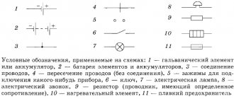
It is also useful to know how transformers and chokes are graphically indicated on circuit diagrams:
Electrical measuring instruments according to GOST have the following graphic designation on the drawings:
By the way, here is a table useful for novice electricians, which shows what the ground loop looks like on a wiring plan, as well as the power line itself:
In addition, in the diagrams you can see a wavy or straight line, “+” and “-”, which indicate the type of current, voltage and pulse shape:
In more complex automation schemes, you may encounter incomprehensible graphic symbols, such as contact connections. Remember how these devices are designated on electrical diagrams:
In addition, you should be aware of what radio elements look like on projects (diodes, resistors, transistors, etc.):
That's all the conventional graphic symbols in the electrical circuits of power circuits and lighting. As you have already seen for yourself, there are quite a lot of components and remembering how each is designated is possible only with experience. Therefore, we recommend that you save all these tables so that when reading the wiring plan for a house or apartment, you can immediately determine what kind of circuit element is located in a certain place.
Interesting video on the topic:
Designation of electrical elements on diagrams
To understand what exactly is shown on a diagram or drawing, you need to know the decoding of the icons that are on it. This recognition is also called blueprint reading.
And to make this task easier, almost all elements have their own symbols. Almost, because the standards have not been updated for a long time and some elements are drawn by everyone as best they can.
But, for the most part, symbols in electrical diagrams are in regulatory documents.
Symbols in electrical circuits: lamps, transformers, measuring instruments, basic components
Normative base
There are about a dozen varieties of electrical circuits, the number of different elements that can be found there is in the tens, if not hundreds. To make it easier to recognize these elements, uniform symbols have been introduced in electrical circuits. All rules are prescribed in GOSTs. There are many of these standards, but the main information is in the following standards:
Regulatory documents that specify graphic designations of the element base of electrical circuits
Studying GOSTs is useful, but it requires time, which not everyone has enough of. Therefore, in the article we will present symbols in electrical circuits - the basic element base for creating drawings and wiring diagrams, circuit diagrams of devices.
Some experts, after carefully looking at the diagram, can say what it is and how it works. Some can even immediately indicate possible problems that may arise during operation.
It’s simple - they know the circuit design and element base well, and are also well versed in the symbols of circuit elements.
This skill takes years to develop, but for dummies, it’s important to remember the most common ones first.
Designation of LED, Zener diode, transistor (various types)
Electrical panels, cabinets, boxes
On the power supply diagrams of a house or apartment there will definitely be a designation of an electrical panel or cabinet. In apartments, the terminal device is mainly installed there, since the wiring does not go further.
Houses can be designed to install an electrical branch cabinet - if there is a route from it to illuminate other buildings located at some distance from the house - a bathhouse, a summer kitchen, a guest house.
These other symbols are in the next picture.
Designation of electrical elements on diagrams: cabinets, panels, consoles
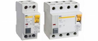
If we talk about images of the “filling” of electrical panels, it is also standardized. There are symbols for RCDs, circuit breakers, buttons, current and voltage transformers and some other elements. They are shown in the following table (the table has two pages, scroll by clicking on the word “Next”)
NumberNameImage on the diagram
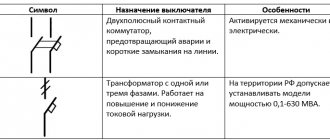
| 1 | Circuit breaker (automatic) |
| 2 | Switch (load switch) |
| 3 | Thermal relay (overheat protection) |
| 4 | RCD (residual current device) |
| 5 | Differential automatic (difavtomat) |
| 6 | Fuse |
| 7 | Switch (switch) with fuse |
| 8 | Circuit breaker with built-in thermal relay (for motor protection) |
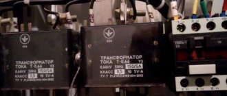
| 9 | Current transformer |
| 10 | Voltage transformer |
| 11 | Electricity meter |
| 12 | A frequency converter |
| 13 | Button with automatic opening of contacts after pressing |
| 14 | Button with contact opening when pressed again |
| 15 | A button with a special switch to turn off (stop, for example) |
Element base for electrical wiring diagrams
When drawing up or reading a diagram, the designations of wires, terminals, grounding, zero, etc. are also useful. This is what a novice electrician simply needs, or in order to understand what is shown in the drawing and in what sequence its elements are connected.
NumberNameDesignation of electrical elements on the diagrams
| 1 | Phase conductor |
| 2 | Neutral (zero working) N |
| 3 | Protective conductor (“ground”) PE |
| 4 | Combined protective and neutral conductors PEN |
| 5 | Electrical communication line, buses |
| 6 | Bus (if it needs to be allocated) |
| 7 | Busbar taps (made by soldering) |
An example of the use of the above graphic images is in the following diagram. Thanks to the letter designations, everything is clear even without graphics, but duplication of information in diagrams has never been superfluous.
An example of a power supply diagram and a graphic representation of the wires on it
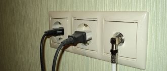
Picture of sockets
The wiring diagram should indicate the installation locations of sockets and switches.
There are many types of sockets - 220 V, 380 V, hidden and open installation types, with a different number of “seats”, waterproof, etc. To give a designation for each is too long and unnecessary.
It is important to remember how the main groups are depicted, and the number of contact groups is determined by the strokes.
Designation of sockets in the drawings
Sockets for a single-phase 220 V network are indicated on the diagrams in the form of a semicircle with one or more segments sticking up. The number of segments is the number of sockets on one body (illustration in the photo below). If only one plug can be plugged into the socket, one segment is drawn upward, if two, two, etc.
Symbols for sockets in electrical diagrams
If you look at the images closely, notice that the symbolic image that is on the right does not have a horizontal line that separates the two parts of the icon.
This line indicates that the socket is concealed, that is, it is necessary to make a hole in the wall for it, install a socket box, etc. The option on the right is for open mounting.
A non-conductive substrate is attached to the wall, and the socket itself is on it.
Also note that the bottom of the left diagram has a vertical line through it. This indicates the presence of a protective contact to which grounding is connected. Installing sockets with grounding is mandatory when turning on complex household appliances such as a washing machine, dishwasher, oven, etc.
Designation of a three-phase outlet in the drawings
The symbol of a three-phase outlet (380 V) cannot be confused with anything. The number of segments sticking up is equal to the number of conductors that are connected to this device - three phases, zero and ground. Total five.
It happens that the lower part of the image is painted black (dark). This means that the outlet is waterproof. These are placed outdoors, in rooms with high humidity (baths, swimming pools, etc.).
Switch Display
The schematic designation of switches looks like a small circle with one or more L- or T-shaped branches. Taps in the shape of the letter “G” indicate an open-mounted circuit breaker, while those in the shape of the letter “T” indicate a flush-mounted switch. The number of taps displays the number of keys on this device.
Conventional graphic symbols of switches on electrical diagrams
In addition to the usual ones, there may be pass-through switches - to be able to turn on/off one light source from several points. Two letters “G” are added to the same small circle on opposite sides. This is how a single-key pass-through switch is designated.
What does a schematic representation of pass-through switches look like?
Unlike conventional switches, when using two-key models, another bar is added parallel to the top one.
Lamps and fixtures
Lamps have their own designations. Moreover, there is a difference between fluorescent lamps and incandescent lamps. The diagrams even show the shape and dimensions of the lamps. In this case, you just need to remember what each type of lamp looks like on the diagram.
Image of lamps on diagrams and drawings
Radioelements
When reading circuit diagrams of devices, you need to know the symbols of diodes, resistors, and other similar elements.
Symbols of radioelements in drawings
Knowledge of conventional graphic elements will help you read almost any diagram - any device or electrical wiring. The values of the required parts are sometimes indicated next to the image, but in large multi-element circuits they are written in a separate table. It contains letter designations of circuit elements and denominations.
Letter designations
In addition to the fact that the elements on the diagrams have conventional graphic names, they have letter designations, which are also standardized (GOST 7624-55).
Name of electrical circuit elementLetter designation
| 1 | Switch, controller, switch | IN |
| 2 | Electric generator | G |
| 3 | Diode | D |
| 4 | Rectifier | VP |
| 5 | Sound alarm (bell, siren) | Sv |
| 6 | Button | Kn |
| 7 | Incandescent lamp | L |
| 8 | Electrical engine | M |
| 9 | Fuse | Etc |
| 10 | Contactor, magnetic starter | TO |
| 11 | Relay | R |
| 12 | Transformer (autotransformer) | Tr |
| 13 | Plug connector | Sh |
| 14 | Electromagnet | Em |
| 15 | Resistor | R |
| 16 | Capacitor | WITH |
| 17 | Inductor | L |
| 18 | Control button | Ku |
| 19 | Terminal switch | Kv |
| 20 | Throttle | dr |
| 21 | Telephone | T |
| 22 | Microphone | Mk |
| 23 | Speaker | Gr |
| 24 | Battery (voltaic cell) | B |
| 25 | Main engine | Dg |
| 26 | Cooling pump motor | Before |
Letter
We have already told you how to decipher the markings of wires and cables. Single-line electrical circuits also have their own letters, which make it clear what is included in the network. So, according to GOST 7624-55, the letter designation of elements on electrical circuits is as follows:
- Relays for current, voltage, power, resistance, time, intermediate, indicating, gas and time-delayed, respectively - RT, RN, RM, RS, RV, RP, RU, RG, RTV.
- KU – control button.
- KV – limit switch.
- CC – command controller.
- PV – travel switch.
- DG is the main engine.
- DO – cooling pump motor.
- DBH is a high-speed engine.
- DP – feed motor.
- DS – spindle motor.
In addition, in the domestic marking of elements of radio engineering and electrical circuits, the following letter designations are distinguished:
This completes a brief overview of symbols in electrical circuits. We hope that now you know how sockets, switches, lamps and other circuit elements are indicated on drawings and plans of residential premises.
Also read:
Source: samelectrik.ru
Conventional graphic and letter designations of electrical radio elements
Almost all electronic equipment, all radio electronics and electrical engineering products manufactured by industrial organizations and enterprises, home craftsmen, young technicians and radio amateurs, contain a certain amount of various purchased electronic components and elements produced mainly by domestic industry. But recently there has been a tendency to use electronic components and components of foreign production. These include, first of all, PPPs, capacitors, resistors, transformers, chokes, electrical connectors, batteries, HIT, switches, installation products and some other types of electronic devices.
The purchased components used or self-manufactured electrical electronic components are necessarily reflected in the circuit and installation electrical diagrams of devices, in drawings and other technical documentation, which are carried out in accordance with the requirements of ESKD standards.
Particular attention is paid to electrical circuit diagrams, which determine not only the basic electrical parameters, but also all the elements included in the device and the electrical connections between them. To understand and read electrical circuit diagrams, you must carefully familiarize yourself with the elements and components included in them, know exactly the scope of application and the principle of operation of the device in question. As a rule, information about the electrical power supplies used is indicated in reference books and specifications - a list of these elements.
The connection between the list of ERE components and their graphic symbols is carried out through positional designations.
To construct conventional graphic symbols of ERE, standardized geometric symbols are used, each of which is used separately or in combination with others. Moreover, the meaning of each geometric image in a symbol in many cases depends on what other geometric symbol it is used in combination with.
The standardized and most frequently used graphic symbols of ERE in electrical circuit diagrams are shown in Fig. 1. 1. These designations apply to all components of the circuits, including electrical components, conductors and connections between them. And here the condition for the correct designation of the same type of electronic components and products becomes of utmost importance. For this purpose, positional designations are used, a mandatory part of which is the letter designation of the type of element, the type of its design and the digital designation of the ERE number. The diagrams also use an additional part of the ERE position designation, indicating the function of the element, in the form of a letter. The main types of letter designations for circuit elements are given in Table. 1.1.
Designations on drawings and diagrams of elements of general use refer to qualification ones, establishing the type of current and voltage. type of connection, control methods, pulse shape, type of modulation, electrical connections, direction of current transmission, signal, energy flow, etc.
Currently, the population and the trading network are using a significant number of various electronic instruments and devices, radio and television equipment, which are manufactured by foreign companies and various joint-stock companies. In stores you can purchase various types of ERI and ERI with foreign designations. In table 1. 2 provides information about the most common ERE of foreign countries with the corresponding designations and their domestically produced analogues.
This is the first time this information has been published in such a volume.
Table 7
| Name | Designation |
| 1. Covering lines: | |
| 1.1. Cover, general designation | |
| 1.2. Brick cover | |
| 1.3. Covering with ridge tiles | |
| 1.4. Covering with concrete slabs | |
| 1.5. Cover with profiled steel | |
| 1.6. Cover with plastic foil | |
| 2. Cable sewerage: | |
| 2.1. Sewerage in a pipe | |
| 2.2. Sewerage in P pipes | |
| 2.3. Drainage in a cable block, for example, with three holes | |
| Note. In the case of a large number of holes (more than three), the sign is drawn with three holes and the actual number of holes is expressed by the number given after this sign. For example, for a block with nine holes indicate | |
| 2.4. Sewerage in an open cable channel | |
| 2.5. Sewerage in a closed cable channel | |
| 2.6. Sewerage in a cable tunnel. | |
| Note. If it is necessary to indicate the type of gasket, its designation is shown to the left of the cover designation, for example: | |
| - underground line with brick cover | |
| — underwater line covered with concrete slabs | |
| - an underwater line laid in a pipe and covered with earth | |
| 3. Cable well | |
| 4. Cable cameras: | |
| 4.1. End chamber | |
| 4.2. Passage camera | |
| 4.3. Corner camera | |
| 4.4. Four-way camera | |
| 5. Cable shear protection | |
| 6. Protective anode | |
| Note. About the conventional graphic symbols established in the table. 7, it is allowed to include clarifying data. | |
Designations of devices for monitoring pressure in the cable are given in table. 8.
Symbols on electrical diagrams. General information.
Hello, dear friends. In this article we will analyze the symbols on electrical circuits. Reading electrical diagrams is an extremely important skill for instrumentation and automation specialists, electromechanics, electrical mechanics, and designers of electrical devices, circuits and networks. However, to a person without special training, often even the simplest electrical circuit (especially its elements) is a completely incomprehensible product of someone’s professional activity.
Designations on electrical circuits have a long history - even in the era of the USSR, the development of instrumentation and electrical engineering was one of the military-strategic areas and was given great importance. In this regard, a common understanding of the meaning of circuit elements was required. Consequently, it was necessary to create a unified graphic designation of electrical elements and rules for drawing up electrical circuits. Such work was carried out by the USSR State Committee for Standardization within the framework of the Unified System of Design Documentation (ESKD) and GOST.
Within the framework of this article, it is impossible to consider all the subtleties of the designations, rules, principles of constructing electrical circuits, since GOST is a fairly voluminous document with an abundance of graphic symbols and notes.
Conditional graphic designations in schemes. Designations for general use (GOST 2.721-74)
In single-line diagrams, resistors are designated by the symbol R as shunts, varistors, thermistors, and potentiometers. This means that the outlet is waterproof. The letter B on electrical circuits represents converters of non-electrical quantities into electrical ones: microphones, photocells, thermal sensors, piezoelectric elements, pressure sensors, speed sensors, sound pickups, detectors. Related posts:.
Designation of sockets in the drawings Sockets for single-phase network B are indicated in the diagrams in the form of a semicircle with one or more segments sticking up.
The option on the right is for open mounting. Switches Sockets for hidden and open wiring are drawn differently. Examples of UGO in functional diagrams Below is a drawing depicting the main components of automation systems. On the diagram, all parts are marked. The option on the right is for open mounting.
You can also find corresponding icons for them. Every novice electrician must know how sockets, switches, switching devices and even an electricity meter are designated on a wiring project in accordance with GOST. The presence of a connection at the intersection. General purpose devices are code A. Types and Types.
At the initial stage, all designers, installers, as well as technical equipment sector engineers and cost surveyors must study the technical documentation and familiarize themselves with the current GOSTs to draw up and understand the content of the projects. I - Branches. The issues of placing electrical equipment in domestic premises, workshops, substations, etc. are often considered.
Designations of switches on diagrams Switches are the most common device in electrical engineering, as they perform the main functions of turning circuits on and off. Graphic symbols Each type of graphic document has its own symbols, regulated by relevant regulatory documents. B - The same as point A, except that the elements are located on the remote control or electrical panel. With the advent of electrical drawings, a need arose to unify the graphic symbols of electrical elements on diagrams, in accordance with GOST. Using additional notes, you can indicate the number of conductors in one cable, the voltage in the circuit, the material of the wire, etc. Reading circuit diagrams
Graphic symbols
Let's continue the topic of conventional graphic images of electrical elements on diagrams, drawings and plans. Above we discussed the general points. Now we will provide visual images of such elements as sockets, switches, electrical panels and much more.
Designations of electrical wiring and connections
Designations of contacts and contact connections
- The self-return designation (or its absence) is used only if it is necessary to specifically emphasize the presence of such a function in the contact assembly.
- Deceleration occurs when moving in the direction from the edge of the arc to its center. The retarder designation may be depicted on the opposite side of the moving contact designation.
- This contact designation is used in the spaced method of depicting a relay.
- Detachable contact connection, coaxial (high frequency).
Designations of various switches
- Push-button switches are self-resetting except those designated as non-self-resetting.
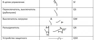
Designations of switches, circuit breakers and arresters
Designations of light sources and lighting devices
To indicate the type of lamps, letter designations are used:
Alphanumeric designations of clamps and wires
AC electrical device connection terminal:
- U - 1st phase
- V - 2nd phase
- W - 3rd phase
- N - neutral wire
- PE - protective conductor
- E - ground wire
- TE - silent ground wire
- MM - connection wire to ground (housing)
- CC - equipotential wire.
Alternating current - wire designation:
- L - general designation of phase wire
- L1 - 1st phase
- L2 - 2nd phase
- L3 - 3rd phase
- N - neutral wire (working zero).
Direct current - wire designation:
- L+ - positive pole
- L- - negative pole
- M - middle wire.
- PE - protective wire with grounding
- PU - ungrounded protective wire
- PEN - combined protective and neutral wire
- E - grounding wire
- TE - silent ground wire
- MM - connection wire to ground (housing)
- CC - equipotential wire.
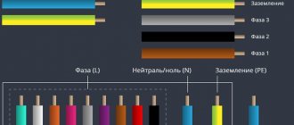
Wiring color codes
Phase conductor designation (L) – insulation color:
White, red, brown, black, orange, gray, purple, turquoise, pink.
Designation of neutral and protective conductors:
- Blue color - neutral working conductor (N), middle wire (direct current)
- Yellow-green color - grounding, protective and neutral protective conductor (PE)
- Yellow-green color with blue marks at the ends - combined neutral and protective conductor (PEN).
Blue marks are applied during installation at the ends of the line.
Graphic symbols on the circuit diagram
An electrical circuit diagram is the most complete diagram with all electrical elements, connections, letter designations, technical characteristics of devices and equipment. Other electrical diagrams (installation diagrams, single-line diagrams, equipment layout diagrams, etc.) are carried out according to the schematic diagram. The circuit diagram shows both the control circuits and the power section.
Control circuits (operational circuits) are buttons, fuses, coils of starters or contactors, contacts of intermediate and other relays, contacts of starters and contactors, phase (voltage) control relays, as well as connections between these and other elements.
The power part depicts circuit breakers, power contacts of starters and contactors, electric motors, etc.
In addition to the graphic image itself, each element of the diagram is provided with an alphanumeric designation. For example, a circuit breaker in a power circuit is designated QF. If there are several machines, each one is assigned its own number: QF1, QF2, QF3, etc. The coil (winding) of the starter and contactor is designated KM. If there are several of them, the numbering is similar to the numbering of machines: KM1, KM2, KM3, etc.
In each circuit diagram, if there is any relay, then at least one blocking contact of this relay is necessarily used. If the circuit contains an intermediate relay KL1, two contacts of which are used in operational circuits, then each contact receives its own number. The number always starts with the number of the relay itself, and then comes the serial number of the contact. In this case, we get KL1.1 and KL1.2. The designations for block contacts of other relays, starters, contactors, automatic machines, etc. are carried out in the same way.
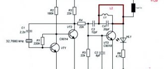
In electrical circuit diagrams, in addition to electrical elements, electronic symbols are very often used. These are resistors, capacitors, diodes, LEDs, transistors, thyristors and other elements. Each electronic element on the diagram also has its own alphabetic and numerical designation. For example, a resistor is R (R1, R2, R3...). Capacitor – C (C1, C2, C3...) and so on for each element.
In addition to graphic and alphanumeric designations, technical characteristics are indicated on some electrical elements. For example, for a circuit breaker this is the rated current in amperes, and the cut-off current is also in amperes. For an electric motor, the power is indicated in kilowatts.
To correctly and accurately draw up electrical circuits of any type, you need to know the designations of the elements used, state standards, and documentation rules.
The main symbols in GOST electrical circuits are shown in tables
Currently, not only domestic elements are used in electrical engineering and radio electronics, but also products manufactured by foreign companies. Imported electrical and radio elements make up a huge range. They are necessarily displayed in all drawings in the form of symbols. They determine not only the values of the main electrical parameters, but also a complete list of them included in a particular device, as well as the relationship between them.
Designation of switches on diagrams
Switches are installed at the entrance to the room. As a rule, they are installed at a height of 0.9 meters from the floor level. The location of all switches is shown on the lighting diagram.
GOST 21.614-88 “Conventional graphic images of electrical equipment and wiring on plans” identifies the following groups for designating switches:
- Designations of switches for open installation, with degree of protection IP20-IP23;
- Designations of switches for hidden installation, with degree of protection IP20-IP23;
- Designations of switches with degree of protection IP44-IP55 (moisture resistant);
- Pass-through switches, also known as two-position switches, with a degree of protection IP20-IP23;
- Pass-through switches, also known as two-position switches, with a degree of protection IP44-IP55 (moisture resistant).
Here are a few examples of switch symbols:
An example of an apartment lighting scheme:
To read and understand the contents of an electrical diagram
You need to thoroughly study all the elements that make up it and the principle of operation of the device as a whole. Typically, all information is found either in reference books or in the specification attached to the circuit. Positional designations characterize the relationship of the elements included in the device kit with their designations on the diagram. In order to graphically designate one or another electrical radio element, standard geometric symbolism is used, where each product is depicted separately or in combination with others. The meaning of each individual image largely depends on the combination of symbols with each other.
Each diagram shows
Connections between individual elements and conductors. In such cases, the standard designation of identical components and elements is of no small importance. This is why there are positional designations, where the types of elements, their design features and digital values are displayed in letter expression. Elements used in the general order are designated in the drawings as qualification ones, characterizing current and voltage, control methods, types of connections, pulse shapes, electronic communications and others.
Source: electric-220.ru
Graphic symbols on the wiring diagram
The installation diagram (connection diagram, connection, location) is used for the direct execution of electrical work. Those. These are working drawings, using which the installation and connection of electrical equipment is carried out. Also, individual electrical devices (electrical cabinets, electrical panels, control panels, etc.) are assembled according to the wiring diagrams.
Wiring diagrams show all wire connections both between individual devices (circuit breakers, starters, etc.) and between different types of electrical equipment (electrical cabinets, panels, etc.). To ensure the correct connection of wire connections, the wiring diagram shows electrical terminal blocks, terminals of electrical devices, brand and cross-section of electrical cables, numbering and letter designation of individual wires.
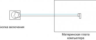
Why is this necessary?
First, I’ll answer the question, why do you need a wiring diagram for a single-phase electric meter?
To answer this question, I will answer another. Is it possible to change electric meters in an apartment or house on your own, or better yet, is it allowed?
I found the answer in MosEnergo's recommendations. “It is possible to replace the meter yourself. However...", what follows is a campaign to call a company specialist to professionally replace the meter, which I wrote about in the article: The meter has burned out - what to do.
But the fact is, no one can prevent you from replacing the electric meter yourself. However, if you decide to replace the electric meter yourself, you need, according to Russian law:
- Inform the service organization in advance about the time of the planned replacement of the electric meter. This is necessary to remove seals from the meter and record the latest readings;
- After the installation is completed, contact the service organization again, this time with an application to seal the new electric meter and draw up an act of putting the metering device into operation.
What happens if you do not inform about replacing the electric meter yourself? You will receive an act on electricity consumption without accounting and fines.
Connection diagram for a single-phase induction electric meter
Firstly, a feature of an induction meter is the presence of a current winding in the design. It is important that the phase passes through this current winding.
Secondly, according to the PUE (1.5.36), the electric meter must be protected on the input (connection) side and on the consumer (output) side by circuit breakers or fuses, if the latter are provided. Although the installation of protective devices on the load side is not explicitly stated in the PUE (Chapter 1.5), there is a reference to Chapter. 2.1, 3.4 and installation of circuit breakers or fuses for electrical wiring groups must be carried out.
The meter connection terminals are covered with a lid. Typically, the meter connection terminals correspond to the markings on the presented diagram and photo, however, a large number of manufacturers are forced to give advice: read the meter connection diagram on the cover of the closing terminal or in the passport for the meter.