What is it for?
A phase and voltage control relay is a device that is necessary when connecting equipment to a system with three phases, as well as in situations where it is important to maintain correct alternation.
In practice, the product is used when equipment is frequently transferred, when changing the phasing may cause damage or incorrect operation.
A striking example is a screw-type compressor, the incorrect connection of which and switching on for more than five seconds leads to breakdown of an expensive product.
The phase and voltage monitoring relay allows you to identify the following problems:
- Break of any phase;
- Increase or decrease in voltage above (below) a given level;
- Phasing violation (phase connection order);
- Break of “zero”;
- Asymmetry of I and U (here we are talking about phase imbalance, when the angle between the vectors is significantly more or less than 120 degrees).
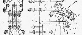
The schematic diagram of the device is shown below.
Some relays provide the ability to change the settings for the upper and lower limits U, as well as T (time) of operation.
As a rule, the output contact group of the relay is “dry”. In this case, there are two options available - normally closed and open. Some models have elements that operate on the induction principle.
Switch selection
There is a wide range of phase switches on the market. They should be selected based on 4 criteria:
- Maximum operating current. This parameter determines how powerful devices can be connected to the switch output. For example, for an ordinary apartment not heavily loaded with electrical appliances, a 16 A automatic switch is suitable.
- Function for adjusting the upper and lower limits of the input voltage. Cheap models do not have these regulators. In them, switching occurs at the input voltage level specified by the manufacturer. In expensive models, you can independently configure at what voltage in L1 the transition to L will occur.
- Status indication method. Simple switch models are equipped with several LEDs. They can light up or blink, depending on the state of the device and the input voltage. More professional models are equipped with seven-segment indicators that can display the voltage value with an accuracy of 1%.
- Functional. Simple models perform a minimal set of functions. They simply monitor the input voltages and make the appropriate switches. Advanced devices can do more. In them you can configure response thresholds, switching time and return to the main phase.
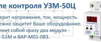
Device with seven-segment indicators
Important! Fundamental phase is a term common to some switch models. In the menu of such devices, you can configure which of the input phases will be considered the main one. When switching, the APF gives preference to the main phase.
Design and principle of operation
Despite the variety of voltage phase control relays, the design features are almost unchanged. The device is based on microprocessors with an embedded program and the ability to customize. This design ensures reliable operation and low maintenance.
The design of the product also includes a circuit that calculates the order of the arrangement (sequence) of phases, and also monitors the compliance of the current situation with the program that is embedded in the relay.
On the simplest models, three phases and a neutral conductor are connected to the input, and a relay with a changing contact is provided at the output terminals.
Voltage to the internal circuit is usually supplied from the first phase (L1). For clarity, a pair or more indicators are installed (much depends on the product model) and the manufacturer.
More expensive relays have a regulator that allows you to change the setting over time (see photo above). Thanks to this option, you can increase or decrease the relay response time when executing a specific program.
In addition, many devices have a circuit that responds to a decrease or increase in voltage.
The operation of the U phase control relay is based on the separation of negative sequence harmonics (from 2 and above). In this case, only harmonics that are multiples of “two” are used, that is, “fourth”, “sixth”, “eighth” and other harmonic components. They appear in the event of a break in any of the supply phases.
To isolate such U, special filters (also negative sequence) are used, the role of which is played by analog-type filters. They include active and reactive units (resistors and capacitors, respectively).
Phase selection relay. Automatic phase changer for critical load
Hello, dear readers of the site!
I suggest you consider using such an interesting device as a phase selection relay .
With three-phase power supply to apartments and, especially, private houses, it is not uncommon for one or more phases to experience voltage drops or surges. Sometimes there is a long-term loss of one of the phases.
Most modern electrical panels use non-switching lines, low-current switchboards, security alarm systems, video surveillance, and access control. The HOLIDAY button (the so-called MASTER SWITCH) is used in conjunction with the contactor, controlling its winding, which is connected to one of the phases.
How to organize uninterrupted power supply in these schemes?
One such solution is to use phase selection relays to switch important loads and electrical appliances to the best of the three phases.
Of course, in combination with other devices and circuits that increase the reliability and safety of the power supply system!
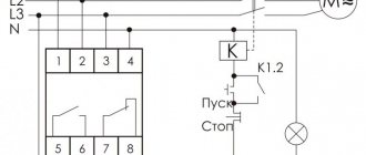
Let's consider a typical connection diagram for an automatic phase selection relay using additional contactors. This circuit allows you to connect a load of any power through a relay.
For example, consider a circuit with RVF-02; it is quite compact and is installed on a DIN rail in the electrical panel.
Three phases and zero are connected to the input of the RVF-02 relay (terminals A1, A2, A3 and N). Output terminals B1, B2 and B3 are connected to the windings of additional contactors that control important loads.
In the circuit of contactor windings, for protection against overcurrents, it is necessary to install automatic switches or fuse links.
Terminal contact Y1 monitors the state of the contactors to prevent sticking and phase-to-phase shorting.
The phase selection relay analyzes the parameters of the external network, and if they are normal, it connects the best or priority phase. In our example - phase A.
It is advisable to set the priority phase in the relay settings, so that when the network parameters return to normal, the load is returned to the priority phase. This eliminates possible unwanted phase imbalance.
If a jump, sag or accident occurs in one of the phases, the phase switch analyzes the remaining two phases and switches the load to the more optimal one.
When the voltage returns to normal, RVF-02 returns the load to the priority phase.
For a detailed step-by-step description of the circuit with a phase selection relay, see the video:
Phase selection relay. How? For what? Scheme.
Types
The most popular types of relays designed for phase control include EL models of the following series - 11, 12, 13, 11MT and 12MT.
It is important to take into account that the scope of application of the product depends on their types of voltage phase control relays (EL):
- 11 and 11 MT - protection of power supplies, participation in the automatic transfer system, power supply of converters and generator sets.
- 12 and 12MT - to protect cranes with a power not exceeding 100 kW.
- 13 - used when connecting electric motors of a reversible type with a power of up to 75 kW.
The devices are fixed on a special DIN rail or only with screws (depending on the situation).
Features of switch operation
If the device is installed in the electrical panel for the first time, it will take some time to fine-tune and adjust it. This especially applies to houses with old electrical networks, where the voltage in the outlet can vary greatly depending on the time of year and day.
In winter, most residents of private houses actively use electric heaters. Therefore, significant voltage drops should be expected. They will affect the operation of the switch. The APF will click the relay more often to select the phase with the most suitable voltage.
Frequent switching is also observed at night. Residents go to bed, electricity consumption is noticeably reduced. Accordingly, the mains voltage increases. The device also begins to switch in search of the optimal phase.
A relay is an electromechanical device. During operation, it creates characteristic clicks. When going to bed, no one wants to listen to the sound of a relay switching. Therefore, it is recommended to install this device away from living rooms.
Characteristics
Modern phase control relays are selected taking into account the following characteristics:
- VOLTAGE. Operating U directly depends on the equipment specification. For example, EL Series 11 can operate at voltages from 100 to 415 V (including 110 V, 220 V, 380 V and 400 V). As for EL 13, they operate on voltages of 220 and 380 V.
- OPERATION LIMIT. This parameter also depends on the type of relay and the current situation. Thus, with a symmetrical decrease in voltage, EL series 11, 12 and 13 devices have a minimum limit of 0.7; 0.5 and 0.5 Ufn respectively. In the event of a break in one or more phases, all relays will operate. If the alternation is disrupted, then models EL11 and 12 recognize the problem and close the contact group, but EL13 does not.
- DELAY TIME. This indicator reflects how much the response of the voltage phase control relay is delayed when the required setting is reached (the specified threshold value). For models EL11 and 12 this figure is from 0.1 to 10 seconds (depending on the adjustment), and for EL13 - up to 0.15 seconds.
- WORKING TEMPERATURE. As in the cases discussed above, the situation here depends on the type of relay. EL types 11 and 12 operate from 40 degrees below zero to 40 degrees above zero. As for EL13, these relays have a smaller range - from -10 to +45 degrees Celsius.
- Storage temperature - from -60 to +50 degrees Celsius.
- Product weight - 300 grams (EL 11 and 13) and 250 grams (EL 12).
Subtleties of choice
When choosing a voltage phase control relay, you need to focus on the technical parameters of the device that is connected to the circuit.
For example, consider a situation when you need to select a model for connecting an ATS.
The algorithm of actions is as follows:
- WE DETERMINE THE CONNECTION METHOD - with or without “zero”.
- WE DETERMINE THE PARAMETERS. For an ATS circuit, it is important that the device monitors the fact of phase failure and the phase sequence. In this case, the delay time should be in the range between 10 and 15 seconds. Control of oscillations U greater or less than the set point is required. To switch a relay with the 0th wire, visual inspection is required for each phase.
After analyzing the requirements considered, preference can be given to EL11E.
In addition, when choosing, you need to take into account the modification of the relay. For example, domestically produced devices are designated as EL.
As for foreign products, their markings are somewhat different. For example, RANA B380 A A 3 C. Here “RANA” is the name of the series, B380 is the voltage 380V. The next two letters A are regulation using a potentiometer and the type of installation (for DIN rail). The number “3” indicates the case size of 3.5 cm, and C is the last digit of the marking.
Phase switch device
It should be noted right away that the switch does not affect the quality of energy in any way; uninterruptible power supplies, generators, batteries, and the like are used for this purpose. The PF itself only selects from three phases the one that is most suitable for operation. The conclusion follows from this: the use of the switch is possible only if there are at least two phases. Where only one phase is connected, installing a PF will not change anything.
Switches can be divided into two groups:
- manual control;
- automatic control.
The electric switch is installed after the meter, so if there is a single-phase meter, it will have to be changed to a three-phase one. The power consumption does not change, the tariff remains the same, therefore, the costs of installing a new meter will be associated only with its cost and installation price, as well as with the supply of additional phases.
Using manual type
A three- or four-position cam toggle switch can be used as a manual type PF. The principle of operation of a manual phase switch is reduced to alternately switching on pairs of contacts.
They are available in two types:
- in the body;
- unframed.
The switch consists of a rotating rod on which one or more cams are located. There is a stopper to secure the position. Several pairs of contacts are used:
- movable;
- motionless.
To return to their original position, the moving contacts have a spring. The contacts themselves are usually coated with a layer of silver, which can withstand high temperatures. This is necessary so that when large currents are opened, the contacts do not burn out or fail.
The switch works as follows: when the shaft rotates, the cam closes one pair of contacts through the insulating rods. Further rotation causes the first pair to open and the second to close. Some designs have a position where all contacts are open. This position is called “off” and is designated “0”.
Automatic control
Enterprises produce three-phase automatic phase switches in huge quantities
What should you pay attention to when purchasing? First of all, for switching current. This is the maximum current that this device is capable of breaking.
After all, switching occurs without removing the load. What current is used in the room can be determined by the machines that are in front of the meter (if the meter has not been changed for a long time, then after it).
The second thing that will help you realize your preferences in setting is the display method. Based on this feature, devices can be divided into:
- LED;
- liquid crystal.
In the first case, the indication is made using LEDs; the color of the glow is different, but most often green. Installed at the input of each phase, thereby indicating which phase is currently in use. The liquid crystal display allows, among other things, to monitor the actual voltage.
An automatic three-phase switch works as follows: all connected current sources are under constant control, and the voltage value is measured. As soon as the readings of the main line go beyond the established values, the load is transferred to the reserve phase.
Phase control relay EL-11E (380 V, 50 Hz), RKF, IEK
These phase control relay models are produced by, which has been on the market since 1992. The company is located in St. Petersburg.
The company's activities are based on the development and manufacture of industrial automation devices. During its existence, the company has managed to take a leading position in the manufacture of electronic devices on the Russian market. The number of goods produced exceeds 500 units.
The company's clients include such giants as Gazprom, Russian Railways, Aurora Concern, Lenenergo and others. The company's products are in high demand due to their quality and wide range of models.
Customers have at their disposal electronic time relays, voltage monitoring devices, maximum current relays, lighting control devices and much more.
Description and technical characteristics of relay EL-11E (380 Volt, 50 Hz)
The EL-11E relay has one normally closed, normally open and changeover contact.
The device is designed to control phases in a 3-phase network, operating at an alternating voltage of 380 Volts. In practice, it is used to control the presence of U and correct symmetry.
Phase control relay Schneider
The Schneider company is considered one of the best manufacturers of devices in the electrical power industry. The products of this company are actively used both at civilian sites and in large industrial organizations.
The advantages of the company's products include a flexible pricing policy, high quality and special conditions for customers.
The company produces circuit breakers, fuses, load switches and switchboard equipment.
In addition, the Schneider plant produces relays, switches, sockets, contactors and many other devices.
Popular models include relays:
- Control of 1-phase voltage (from 65 to 260 V and time delay from 0.1 to 10 s - RM17UBE
- 3-phase voltage control (208 to 480 V) - RM17TE
- 1-phase voltage control (160 to 280 V, 30 second delay) - EZ9C
- 3-phase voltage control (from 208 to 480 V) - RM17TT00 and others.
ABB phase monitoring relay
ABB has been operating since 1883, which is further confirmation of the reliability and relevance of the Swiss brand’s products.
Initially, the manufacturer produced generators and lighting devices, but in 1891 the production of electrical machines began.
At the present stage, the manufacturer’s offices operate in numerous countries around the world, and their number has exceeded 100.
The company produces and markets products for automation of production, generation and transmission of electricity, protection and automation of various facilities in the energy sector.
The most popular models include the following voltage control relays - CM-PVE, CM-MPS.21S, CM-MPS.41S, CM-PFS and others.
They all differ in voltage level, type of fastening, holding time and other parameters.
How to connect the device? Scheme
Let us immediately note that if a frequency converter is used in the equipment connection circuit, the installation of a voltage control relay is not required.
When connecting the product, it is important to follow the instructions supplied by the manufacturer. In most cases, the diagram is indicated directly on the product body, which simplifies installation and connection.
Connection to the product contacts at the input and output is carried out using wires, and they are secured using special clamps.
Wires of 2.5 “squares” or double wires of 1.5 “squares” are used as a conductor. When connecting, it is important to observe the correct rotation of the three phases.
The connection diagram can be different, both with and without a “zero” wire. The first option is usually found in private houses and apartments. In this case, the load is evenly connected to each phase. If there is a deviation from the norm, the relay is activated.
Diagram and video of connection EL-11M-15
Features of connection and operation of the device
The automatic switch is installed immediately after the electric meter. The device connected to the line tests the condition of the conductors and connects the circuit to the core whose parameters best correspond to the required ones. During operation, the device constantly monitors the voltage, which should not go beyond the established limits.
Operating procedure and device of the phase switch in the video:
During operation, voltage control is carried out not only on the priority phase, but also on two backup ones. This is necessary so that if the parameters on the main conductor are violated, without delay, select another core to switch the power. If the voltage on both backup lines is within acceptable limits, switching proceeds from L1 to L2 and further (phase designations are on the device body, each has its own LED).
If the potential difference does not correspond to the specified parameters on any conductor, power will not be supplied through them. When the voltage on the priority line normalizes, the connection will be made to it first.