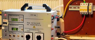
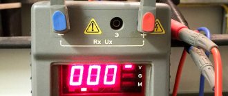
Device for testing power cables up to 10 kV (AID-70M)
During its operation, the cable is constantly exposed to certain external unfavorable factors: temperature changes, pressure and soil displacement, and other loads that in one way or another affect the condition of the cable insulation. And since insulation cannot last forever, testing power cables is an absolutely necessary activity. In any case, it will at least give you an idea of the condition of the power cable.
Cable testing with increased voltage is carried out in accordance with GOST. The voltage used in testing is also set according to technical specifications or GOST for specific cables.
Testing of power cables with impregnated paper insulation
When performing high-voltage tests on a cable with a metal sheath and screen , the screen and sheath are connected and - if the test takes a long time - an initial voltage is applied equal to about 40% of the full test voltage. Then testing the cables with 10 kV voltage is continued, gradually increasing it to the level of the established test voltage. The increase should not be faster than 1 kV per second. When adjusting stepwise, the voltage at each step should not exceed 5% of the main value of the full test voltage.
When a high-voltage test of a power cable is performed to measure the magnitude of the insulation breakdown voltage, the voltage is gradually increased until breakdown, and the rate of increase is no more than 2 kV per second.
It is imperative to conduct high-voltage tests of cables before commissioning to guarantee reliable and trouble-free operation of wired power cable lines, as well as systematically organize scheduled preventive tests of cable products. High voltage cable testing must include visual inspection and a series of test checks.
Specialists have all the necessary equipment, experience and permits for testing power cables over 1000V. Contact us by phone: (495) 669-40-84
The decision on the method of testing power cables, and what equipment will be used, is made by the specialists performing the tests. The measurement results are recorded in the power cable test report .
Testing power cable lines with voltage up to 10 kV using a megohmmeter
Tests are carried out using a megohmmeter for a voltage of 2.5 kV. Since networks with voltages up to 10 kV abut Power Centers, when supplying voltage, protocols are used that meet the requirements of the centers. Tests are being carried out:
- newly laid and after relaying - acceptance;
- those in operation - planned according to schedule;
- after repair or long-term shutdown - unscheduled;
- testing of cable lines as part of work to determine the location of damage and repair cable lines - diagnostic;
Frequency of testing 0.4 kV cables
For cables with a voltage of 0.4 kV, laid and re-routed cables are tested before switching on and after repair work.
The cost of testing power cable lines with voltage up to 10 kV starts from 1,500 rubles per piece.
Testing cables for voltages up to 1 kV for balance holders is not regulated. Therefore, tests are carried out in accordance with the PUE and PTEEP once every 1-2 years.
Frequency of testing 6-10 kV cables
- for main and backup cable lines supplying especially critical consumers - once a year;
- main cable lines - once every three years;
- backup cable lines - once every five years;
Lines up to 60 m long, which are outputs from transformer substations to overhead lines, may not be tested.
Test standards for high voltage cables
High voltage cable testing. The magnitude and duration of test voltage application for testing 6-10 kV cables with paper insulation.
| Purpose and objects of testing | U working, kV | U test, kV | Duration, min. |
| Before switching on (newly laid, after re-laying) | 6 | 36 | 10 |
| 10 | 60 | 10 | |
| In use | |||
| Scheduled and unscheduled | 6 | 30 | 5 |
| 10 | 30 | 5 | |
| Cable lines running along complex routes and supplying especially critical consumers | 6 | 20 | 5 |
| 10 | 40 | 5 | |
| CL with a service life of more than 15 years | 6 | 18 | 5 |
| 10 | 40 | 5 | |
| CL with a service life of more than 25 years | 6 | 18 | 5 |
| 10 | 30 | 5 | |
| When moving from 6 kV to 10 kV | |||
| With a cable design of 10 kV | 10 | 50 | 5 |
| With a cable design of 6 kV | 10 | 40 | 5 |
The magnitude and duration of test voltage application for testing 6-10 kV cables with cross-linked polyethylene insulation.
| Purpose and objects of testing | U working, kV | U test, kV (alternating voltage 0.1 Hz ultra-low frequency) | Duration, min. |
| Cable lines made of single-core cable with cross-linked polyethylene insulation, newly laid (after repair) | 6 | 12 | 30 (20) |
| 10 | 18 | 30 (20) | |
| 20 | 36 | 30 (20) | |
| Plastic sheaths (XLPE insulated single core cable hoses) | From 10 and above | 10 | 1 |
The magnitude and duration of test voltage application for testing cables up to 1(0.4) kV with paper, plastic and PVC insulation.
| Purpose and objects of testing | U working, kV | U test, kV | Duration, min. |
| Paper insulated cable lines | |||
| Newly laid, after relaying and after repair | Newly laid, after relaying and after repair | 2.5 (constant, megohmmeter) | No more than 0.5 |
| Cable lines with plastic insulation | Up to 0.66 kV | 2.5 (constant, megohmmeter) | No more than 0.5 |
| Up to 0.66 kV | 3.5 (industrial frequency) | 5 |
During the tests, the insulation characteristics are checked for compliance with the standards and instructions of the manufacturer.
Rectified current high voltage test
Power cables with voltages above 1 kV are tested with increased rectified current voltage. The magnitudes of the test voltages and the duration of application of the normalized test voltage are given in Table 1.8.39 (PUE clause 1.8.40)
| Cable insulation and grade | Test voltage, kV, for cables for operating voltage, kV | Test duration, min | |||
| 2 | 3 | 6 | 10 | ||
| Paper | 12 | 18 | 36 | 60 | 10 |
| Rubber brands GTSh, KSHE, KSHVG, KSHVGL, KSHBGD | — | 6 | 12 | 20 | 5 |
| Plastic | — | 15 | 36 | 60 | 10 |
Requirements and test standards for 6-10-35 kV cable lines
All work on testing and weapons of mass destruction can be carried out by personnel authorized for these works and having the appropriate mark in the safety certificate. When carrying out this work, you can only use testing and measuring equipment that has been tested and annually certified by the Institute of Electrical Networks. The use by personnel of electrical networks of installations belonging to other organizations (CP, subscribers) is prohibited .
CL 6-10-35 kV are tested:
- newly laid and after relaying - before backfilling the trench and before switching on;
- those in operation - scheduled according to schedule, unscheduled - after repair or long-term shutdown (in excavation, etc.).
CL up to 1 kV are tested:
- newly laid and after relaying - before switching on;
- unscheduled - after repairs.
CL 6-10-35 kV are tested:
- Once a year - for PKL and RKL supplying especially responsible consumers;
- 1 time every 3 years - all other PCLs;
- Once every 5 years - all other RCLs;
- Internal cable jumpers in RP and TP are tested only when newly laid and after repair.
The standards allow not to test cable lines up to 60 m long, which are outputs from distribution points and transformer substations to overhead lines.
A one-time test of several series-connected RCLs with disconnection of power transformers is allowed; beams of parallel cable lines; double or paired CLs.
The magnitude and duration of the test voltage applied to the cable conductors is given in Table. 1.
Table 1
| Purpose and objects of testing | Urab, kV | Urab, kV | Duration, min. |
| 1. Paper insulated cable lines | |||
| 1.1. Before switching on (CLs are fully or partially made with a new cable) | up to 1 kV | 2.5 (megaohmmeter) R insulation must be at least 0.5 MOM | |
| 6 | 36 | 10 | |
| 10 | 60 | 10 | |
| 35 | 175 | 10 | |
| 1.2. In operation, scheduled according to schedule and unscheduled | up to 1 kW | 2.5 (megaohmmeter after repair) | |
| 6 | 30 | 5 | |
| 10 | 50 | 5 | |
| 35 | 175 | 5 | |
| CLs running along complex routes and supplying especially critical consumers (excluding CLs running in metro tunnels) | 6 | 20 | 5 |
| 10 | 40 | 5 | |
| CL with a service life of more than 15 years (except for cables in metro tunnels) | 6 | 20 | 5 |
| 10 | 40 | 5 | |
| CL with a service life of more than 25 years | 6 | 18 | 5 |
| 10 | 30 | 5 | |
| 1.3. When converting cable lines from 6 kV to 10 kV with a cable design of 10 kV | 10 | 50 | 5 |
| with a 6 kV cable design | 40 | 5 | |
| 1.4. Before turning on, if the CL was off for more than 5 days | 6 | UPK -0.1M | |
| 10 | |||
| 1.5. Newly laid cables with a design of 10 kV connected to a 6 kV network | 6 | 60 | 10 |
| 2. Cable lines with plastic insulation | |||
| newly laid | up to 0.66 | 3,5 | 5 |
| 2.5 (megaohmmeter) alternating voltage 50 Hz | |||
| after renovation | up to 0.66 | ||
| 3. Cable jumpers in RP, TP, | |||
| including: | |||
| made with a single-core cable with cross-linked polyethylene insulation | 6 | 12 | 5 |
| 10 | 18 | 5 | |
| 20 | 25 | 10 | |
| 4. CLs made of single-core cable with cross-linked polyethylene insulation | alternating voltage 0.1 Hz (ultra-low frequency-VLF) | ||
| 6 | 12 (3Uph) | 30 20 (after repair) | |
| 10 | 18 (3Uph) | — | |
| 20 | 36 (3Uph) | — | |
| 5. Plastic sheaths (single-core cable hoses with XLPE insulation) | from 10 and above | 10 | 1 |
17277
Bookmarks
Comment 2
Comments 2
Krokhmal Sergey
Good afternoon.
Please inform me on the basis of which regulatory document the table was compiled (The magnitude and duration of the test voltage applied to the cable conductors is given in Table 1.; https://www.energoboard.ru/information/142-trebovaniya-i-normi-ispitaniy- kabelnih-liniy-6-10-35-kv.html) December 6, 2013 at 12:25
Bookmarks
Alexander
It looks like the table was taken from the master ISS reference book.
There are mistakes that a specialist would not make. August 24, 2015 at 12:45 pm
Bookmarks
Write a comment
Leakage currents and asymmetry factors for power cables
During testing, the nature of the change in leakage current is noted. The cable is considered to have passed the test in the absence of insulation breakdown, sliding discharges and shocks (or increase) of the leakage current after the test voltage reaches the standard value. (Table 1.8.40 PUE clause 1.8.40) After testing, a working cable must be discharged .
| Cables voltage, kV | Test voltage, kV | Permissible values of leakage currents, mA | Acceptable values of the asymmetry coefficient (Imax/Imin) |
| 6 | 36 | 0,2 | 8 |
| 10 | 60 | 0,5 | 8 |
The absolute value of the leakage current is not a rejection indicator. Cable lines with satisfactory insulation must have stable leakage current values. During the test, the leakage current should decrease. If there is no decrease in the leakage current value, or if it increases or the current is unstable, the test should be carried out until a defect is identified, but not more than 15 minutes.
- Measurement of current distribution along single-core cables is carried out on lines of all voltages. The unevenness of current distribution on the cable should not exceed 10%.
- Ground resistance measurements are carried out on all voltage lines for terminations. The resistance values must correspond to those given in the PUE.
High voltage cable testing
Testing a 10 kV cable with increased voltage makes it possible to detect problems not detected by a megger and bring it to breakdown in faulty places. The increased voltage is supplied through a high-voltage wire of special equipment to 1 core, and portable grounding is applied to the rest. The voltage increases smoothly to a maximum of 60 kW.
The required test time (5-10 minutes) is then counted, and current and voltage leakage are carefully monitored. At the final minute, the current leakage is counted according to the readings of the microammeter. The voltage gradually decreases to zero. The high-voltage terminal of the equipment is grounded. All conductors are checked in the same way. The results of the checks are entered into a notebook. The permissible difference in current leakage between phases is not higher than 50%.
The cable is considered to have passed the test in the absence of:
- current surges, breakdowns;
- reducing the resistance of the insulating layer;
- increase in current leakage;
- surface discharges.
If the leakage current increases, the cable line is allowed to operate provided that it is monitored and tested more often. When a breakdown is detected, work is suspended and a search for faulty areas begins.
| SCL, kV | voltage, kV | DTU, mA | DKA |
| 6 | 36 | 0,2 | 8 |
| 10 | 45 | 0,3 | |
| 50 | 0,5 | ||
| 60 |
T. Permissible leakage currents and asymmetry coefficients for SCL.
Test report for power cable line above 1000V
Below is an example of filling out the test report tables:
In the “General Data” table, in the column number of couplings, I suggest recording not only intermediate couplings, but also end couplings. In this case, even on a cable without intermediate couplings, it is necessary to indicate the number 2 in this column. With this filling, this column remains empty only in the case of testing the power cable, for example on a drum, or before laying and installation.
| Beginning of CL | End of CL | Cable type | Length, m | Number of couplings | Note |
| ZRU, cell 1 | TP-2, T-1 | SBG 3x35 | 250 | 2 | — |
In the table “High Voltage Insulation Test”, in the leakage current column, it is necessary to record the current at the beginning of the test (steady-state) and the current at the end of the test before removing the voltage.
| Name | Cable | Note | ||
| L1–(L2+L3+^) | L2–(L1+L3+^) | L3–(L2+L1+^) | ||
| Usp (kV) | 60 | 60 | 60 | |
| Iut. (µA) | 110/100 | 120/100 | 110/80 | start/end |
| Cont. tests | 5 minutes | 5 minutes | 5 minutes | |
