Device design with two keys
True to its name, the two-key device from the front looks like an electrical device, on the front panel of which there are two plastic buttons enclosed in a decorative frame. If the plastic parts are removed, you can see two movable panels that move the contacts.
Double with plastic parts removed.
If you continue to disassemble the device further, you can see the contact group and a visual diagram of its connection.
Contact group with two pairs of contacts.
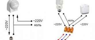
The electrical circuit of the twin consists of two switches. Their inputs are combined and connected to a common terminal.
Electrical circuit diagram.
These terminals can be seen on the back of the device:
- general (it is often designated by the letter L; in the same way, in many cases, the wire that is connected to this terminal is marked);
- two outgoing (L1 and L2), respectively, these terminals are equivalent and are each controlled by its own key.
View from the back.
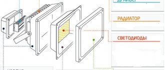
Some devices are equipped with a backlight chain. It is performed on the basis of an LED or neon lamp.
Backlight circuit diagram.
In most cases, the backlight circuit is placed on only one pair of contacts. This must be taken into account, for example, when looking for reasons for blinking LED lamps.
View of the device with backlight.
What types of switches are there with on indication?
Illuminated Triple Switch
Illumination in electrical switches is a neon bulb or LED. Visually it is almost impossible to distinguish them; the only difference is that neon lamps consume less electricity, but create a larger voltage drop. The minimum current for LEDs to glow is 2 mA, the voltage drop is 2 V, and for neon varieties these figures are 0.1 mA and 70 V, respectively. This is important to consider when choosing an electrical switch.
Switches with an indicator may not work correctly with different types of lamps. The design works smoothly and efficiently with halogen and incandescent lamps. It is better to refuse to use LED and energy-saving ones or take special measures. The most common malfunctions are the light blinking in the off position of the switch, the indicator in the switch does not light up.
The backlight can be equipped on all types of switches and with any number of keys. The location of the glowing indicator can be different: at the top or in the middle of the key, in the center or at the bottom of the device body itself.
Connection diagrams
There are three main uses for a two-pin switch:
- turning on two different lighting fixtures in different rooms or areas;
- turning on two different lighting systems in one room;
- control of lamps or groups of lamps in multi-arm chandeliers.
Electrical diagram of the operation of a two-key player.
Fundamentally, the connection diagram for a two-key switch will be the same in both cases, but the laying of the conductor products will be different.
Laying cables for two independent lamps.
In the first two cases, a copper cable containing conductors is laid to each lamp:
- phase (L), indicated in red in the figure;
- zero (N) – blue;
- protective (PE) – yellow-green.
Important! If incandescent lamps are used in the TN-S or TN-CS lighting system, then the PE conductor on the consumer side is not connected (there is nowhere to connect it), but this conductor must be laid. In case of replacement of lamps in the future.
You will also need a three-wire cable from the switchboard to the box and a three-wire cable to connect the two-button device.
Laying cables for a multi-arm chandelier.
For a single luminaire with two groups of lamps, the following copper cable products will be required:
- three-core cable from the switchboard to the junction box (two-core in the absence of a PE conductor);
- four-core cable from the box to the lamp (three-core in the TN-C system);
- a three-conductor cable from the box to the switch (regardless of the presence of protective grounding).
It is recommended to use cable products with insulation color-coded or numbered conductors. To connect the switch, it is advisable to use a cable without a conductor with yellow-green insulation, so as not to mislead repairmen in the future.
Ways to get rid of “blinking” lamps
Everyone loves backlit switches - beautiful, convenient, inexpensive, practical. But they are ideally compatible only with incandescent lamps - conventional or halogen. It’s generally better not to use them with housekeepers - they blink constantly. Can work with high-quality dimmable LEDs. But only high quality ones. Read - dear. And then, over time, if there is a low-quality transformer somewhere, problems may begin. This means that either the lamps will shine at full intensity, or they will “burn out” when turned off. So, connecting an illuminated switch is only possible with “old” lamps?
Convenient - no need to look on the wall
There is a solution to the problem, and even several. Varying degrees of difficulty. Moreover, not all of them work and do not always work. So you can try them one by one. Here's how to make friends with an illuminated switch and LED bulbs:
- Screw one incandescent lamp into a chandelier with LED or housekeepers. The power is selected experimentally.
- If the LEDs are “built-in” and there is no way to add an incandescent lamp without damaging the chandelier, a capacitor with a capacity of 0.22 μF, rated at 630 V, is installed parallel to the chandelier. The same solution is suitable for groups of built-in LED lamps. A capacitor is placed in front of the first lamp in the branch, parallel to it.
- The radical solution to the problem is to “bite out” the backlight circuit. This will not affect the functionality of the switch in any way. The second way is to pull out the neon lamp. This is easier if the circuit is integrated into the body, as is done in Legrand illuminated switches.
Just remove the highlight
- The most correct, and as usual, the most complex solution. Bring the neutral from the panel into the socket box, disconnect one end of the backlight circuit from the terminal, and connect it to the neutral. In this case, the backlight will always be on, but there will be no parasitic circuits that power low-resistance lamps (LEDs and housekeepers).
All options except the last one have one drawback. Due to stray currents that flow through the backlight circuit, LED lamps are constantly energized. As long as the current is insufficient to start glowing, this is simply not noticeable. But the built-in voltage converters are “in operation” all the time. How this affects the lamps is not yet very clear, but there is an assumption that they will burn out faster.
Installation instructions
Installing a switch as part of a lighting system consists of several stages. Each stage must be considered in detail.
Selection and installation of a circuit breaker
Any lighting network, regardless of the design of the switching device and the number of keys, must be connected to the distribution device through an automatic switch. It functions as a reusable fuse - it turns off the protected area (conductors and load) in the event of an overload or short circuit. The question of the principles for choosing the rating of the machine is beyond the scope of the review, so it is only worth mentioning that for a network made of copper conductor products, the protective device must be:
- with rated current 10 A;
- with characteristic B or C (in the first case, the device will have higher sensitivity and lower shutdown time when overloaded).
In this case, the machine will operate with a load of up to 2200 W, which is enough to power any reasonable lighting network (especially taking into account the general transition to LEDs). If the load allows, you can install a 6-amp machine. In this case, guaranteed selectivity will be ensured - if there is a short circuit on one outgoing line, only its own device will turn off, and not the common (group), and the remaining serviceable lines will remain in operation. But the feeder load should be no more than 1200 W.
If the case is non-standard and an increased cross-section of the cable cores is used, the rated current of the machine can be selected from the table.
| Conductor cross-section, sq. mm | Application area | Rated current of the protective device, A |
| 1,5 | Lighting networks, instrument circuits | 6 or 10 |
| 2,0 | Sockets, dedicated line for powerful consumers about 3500 kW | 16 |
| 4 | Single powerful electrical appliances (washing machines, ovens, etc.) | 25 |
| 6 | Electric stoves, electric boilers | 32 |
| 10 | Entries to apartments and houses | 40 |
16 A automatic machine with characteristic C.
After selecting and purchasing a circuit breaker, it must be installed in the switchboard. Now all other types of installation have been replaced by mounting electrical appliances on a standard DIN rail.
DIN rail.
This method is the most convenient and fastest. The device snaps onto the rail in one motion.
Installing an electrical appliance on a DIN rail.
After installing a device or group of devices, clamps are installed on both sides. They prevent devices from moving along the rack.
The machine is connected to a phase conductor break. It is customary to bring the feeding end from above, and the outgoing end from below. If you do the opposite, then everything will work - the electromagnetic and thermal releases of the protective device do not care which way the current flows. But in the future it will be more difficult to understand the installation.
Connection diagram of the lighting system to the switchboard.
Important! It is impossible to break the neutral wire by installing a fuse, circuit breaker or other switching device into it!
Selecting the wiring type
Now you need to determine the type of wiring: open or closed. The main argument for closed wiring is the aesthetic component. There are also reasons for hiding wires in the wall:
- minimal risk of damage;
- in the event of a short circuit, a fire will not happen - the conductors will burn out inside the wall;
- Such wiring will not interfere with cosmetic repairs in the future.
The main disadvantage is the laboriousness of wall slitting and the need for special tools and skills for this, as well as for subsequent sealing. Other disadvantages include the following difficulties:
- with determination of the location of the malfunction when it occurs;
- labor-intensive and large amount of work during repairs;
- difficulties with diagnosing the condition of insulation during its natural aging and the appearance of leaks (important when using LED lighting).
All the disadvantages of hidden wiring are the advantages of open wiring and vice versa. The advantages of open cable routing include:
- ease of installation of cable products;
- simple diagnostics and simple repairs if necessary.
The disadvantages include:
- increased likelihood of mechanical damage;
- increased fire hazard (especially in wooden houses);
- problems with subsequent wallpapering, painting walls, etc.
And most importantly, the wires are in plain sight, which does not add aesthetics to the room.
An option is selected after comparing all the advantages and disadvantages of the location.
Preparatory work
Preparation for the installation of a lighting system begins with determining the installation locations of the switch, distribution box, and lamps. After this, cable laying routes are outlined. Further work depends on the selected type of wiring.
Hidden installation is carried out before the walls are finished. Channels for laying cables - grooves - are made along the intended lines. The most convenient way to do them is with a special tool - a wall chaser. Channels made with a grinder or a hammer drill also work well. As a last resort, you can use a hammer and chisel.
Important! It is forbidden to make horizontal grooves in the load-bearing structures of the building! Other restrictions are contained in SNiP 3.05.08-85.
Installation of socket boxes in a concrete wall.
Then you need to make recesses for socket boxes and boxes for wiring wires - this is done using a special cutter (crown).
Installation of socket boxes in a plasterboard partition.
If plastic boxes are attached to a plasterboard partition, boxes of a special design must be used.
Open wiring is done after final finishing . For laying cables, plastic channels or racks are used (if the wiring is done in “Retro” style). To install switches and boxes, you need to secure the pads.
Video: Installing a socket block into a level.
Installation of lamps
There are a great variety of lamps, and their fastening to the ceiling and walls depends on their design and the design of the plane on which they are mounted. For proper mounting, you need to study the instructions for the lighting device and follow it.
The procedure for installing the lamp is from the instructions.
It is advisable to make the connection before installing the lamps (they will interfere and there is a risk of damaging them). If the luminaire is designed to use only incandescent lamps, then phasing is not required. In other cases (LED lamps, energy-saving lamps), the connection order must be followed:
- the phase wire must be connected to terminal L;
- connect zero to terminal N;
- the protective conductor is connected to the PE terminal (often marked with a ground symbol).
Failure to comply with phasing may result in lighting failure.
Connecting a ceiling light fixture.
Installation of a double
The procedure for installing the device in a socket box.
Before installation, the two-button device must be partially disassembled - remove the keys and the decorative plastic frame. Next, connect the wires according to the selected colors. It is advisable to connect the red wire (if there is one in the cable) to the common terminal, which is connected in the junction box to the phase core of the incoming cable - this way there is less chance of mixing up the ends. Wires of any color can be connected to the outgoing terminals. If it turns out that it is more convenient to control a certain lamp with a certain key, switch the wires briefly during operation.
Wire connection stage.
After connecting, the switch must be placed in the socket, open the petals, and secure the metal panel with self-tapping screws.
Fastening the device with self-tapping screws.
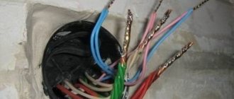
Making connections in the junction box
Cables placed in boxes for unsoldering must be separated:
- shorten to a reasonable length (so that after installation the box can be closed) - this is done using wire cutters;
- remove the top shell - a mechanic's knife will help;
- strip the cores of insulation by 1-1.5 cm - with a mechanic's knife or a special puller.
Connection of conductors in the junction box in the case of two separate luminaires.
Next you need to connect the wires according to the diagram:
- conductors PE and N go through the box in transit and are simply connected to each other in groups;
- the phase conductor from the switchboard is connected to the phase conductor going to the common terminal of the switch;
- the conductors from the switch contacts are connected to the supply conductors of the outgoing cable to consumers according to the diagram.
It is convenient to make connections using clamp terminals. But for reliability, it is better to use screw terminal blocks, although installation in this case becomes somewhat more complicated. You can simply twist and unsolder the conductors, but after that they must be insulated.
Completion of installation work
To complete the installation work, it is necessary to completely plaster the grooves when the wiring is open, and close the cable trays when open. For any type of installation, close the desoldering boxes with standard plastic covers. Next, you can replace the plastic frames and movable keys that were removed before installing the switch and proceed to checking the functionality of the lighting system.
Video block: Connection diagram for a two-key switch with two light bulbs.
Checking the lighting functionality
You can check the correct assembly of the connection diagram for a double household switch by checking the installation using a multimeter or by checking the diagram according to the colors of the cores. If the lighting system is not yet connected to the circuit breaker, you can simulate the operation of the circuit using a battery.
Checking correct installation using a battery.
To do this, you need to connect a battery to the input of the circuit (preferably 9 volts), and a multimeter in voltmeter mode to the terminals of the lamp (you can use a test lamp that is guaranteed to light up at 9 volts). By turning on and off the corresponding key of the switching device, you can check the appearance of voltage on the lighting device. By controlling the polarity of the incoming DC voltage, it is easy to determine the correct phasing. The advantage of this method is that if there are errors in installation, the battery will not produce enough current to overheat or damage the circuit elements.
Installation of a two-button light switch and connecting wires
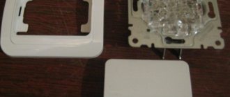
There is nothing complicated in the connection diagram and in the process of installation, installation and connection of wires to the switch contacts. First of all, the switch needs to be disassembled. To do this, remove the keys themselves. If you can’t do this manually by simply pulling them towards you, use an ordinary screwdriver, prying the keys off from the side.
Next comes the insulating decorative backing; it can either be snap-on or screwed on. Remove this frame.
As a result, what you have in your hands is the body itself with the fastenings on the sides and the internal contact part. The main task is to supply voltage from the phase conductor to the common contact. Further, when two keys are closed, this phase will diverge into one or the other lighting circuit.
To find the central contact, look at the marking, since it may not always be located alone and according to class=”aligncenter” width=”596″ height=”600″[/img]
What to do if you don’t understand the inscriptions or they are erased and painted over? Then you need to use a contact screwdriver with a battery-powered tester with a continuity test function. Insert any metal object (nail, screw) into the supposed common contact. You wrap your fingers around it and touch the other two contacts with a screwdriver.
When you press the keys one by one, that is, turn on one - check, then turn off the first and turn on the second - check, the screwdriver LED should light up each time. If this does not happen, then this is not a common contact.
When you have dealt with the contact part of the switch, take the three-core cable VVGng 3*1.5. It is desirable that the colors of the cable cores correspond to the color markings according to GOST. How to determine by color which conductor should be phase and which should be neutral by reading the article “How to distinguish wires by color.”
To connect the common contact, use the gray conductor phase coming from the junction box. Strip the end of the core, insert it between the contact plates and tighten the screw with a screwdriver.
Next, connect the other two wires in the cable to the outgoing contact connectors.
Connecting the conductors directly to the two-key switch itself is now complete. Insert the housing into the mounting box and tighten the mounting screws.
Then you tighten two spacer screws, which help the mounting fork with teeth to rest as much as possible against the walls of the box and firmly hold the switch body inside it.
After this, you can return all the decorative frames and the keys themselves to their place.
Labor protection rules when performing electrical installation
To ensure safety when working in an electrical installation, work must be carried out with the voltage removed. To do this, connect the lighting system to the circuit breaker last.
The switchboard is considered an active electrical installation, therefore, when working in it, several technical measures must be taken:
- turn off the group (input) switch;
- temporarily connect the power bus of the machines to the PE conductor (if available);
- check that there is no voltage on the power bus.
Perform all work wearing dielectric gloves and insulated hand tools. Safety regulations also require the use of dielectric mats.
Clear step-by-step video: Connecting the switch during repairs.
Connecting a chandelier to a single switch
The easiest way to connect a chandelier. The wires of the home electrical wiring and the wires of the lamp are connected in pairs to each other.
- Connect the neutral wire of the chandelier with the neutral wire from the junction box.
- The phase wire from the distribution box must first be connected to the switch and routed under its button. Connect it to the phase wire of the chandelier.
When connecting wires, the most reliable and safe option is to use screw terminals. However, in practice, twisted connections are often isolated with special caps. We strongly do not recommend using PVC tape for insulation; after time, due to its drying out, the quality of the insulation can deteriorate significantly, which can cause a short circuit and is fraught with unpleasant consequences.
Analysis of typical errors
By carefully connecting wires, especially with color-coded wires, the likelihood of error is minimized. But if the conductors are not marked or the installation was carried out in a hurry (with deadlines pressing for the apartment to be delivered), then it is possible to connect the phase wire not to the common terminal of the two-key switch, but to one of the outgoing terminals. Outwardly it appears like this:
- when manipulating one key, one lamp turns on and off in normal mode;
- when manipulating another key, the second lamp does not turn on;
- When two buttons are turned on, both lamps light up.
If such behavior of the lighting system is detected, you need to find out the phasing using an indicator screwdriver and perform rewiring.
But in general, organizing a lighting system with the connection of a household light switch with two keys, although a responsible matter, is quite realistic with a thoughtful approach and average qualifications of the master. Everything can be done independently from scratch. The main thing is that every action must be conscious.
Pros and cons of dual connection
An experienced electrician begins any project to improve a lighting system by optimizing the use of all electrical devices combined into one chain.
An example of an optimized circuit is the traditional lighting arrangement of the “toilet + bathroom” block. On the corridor side, one switch is usually installed, but with two keys.
Thus, the lamp in the bathroom is controlled by one key, and the light bulb in the toilet is controlled by a second. With one movement of your hand, you can perform two actions at once, turning off the lights in one room and turning on the lights in the next one, which is very convenient.
If the switch is installed in the wall between two parts of the bathroom, then choosing a key will not be difficult - it will be located on the side of the desired room
Installing a common switch for two rooms is advisable if they are located nearby. For rooms remote from each other, it is reasonable to use separate electrical installations.
A double switch may also be required when installing a chandelier or sconce with two bulbs. Separate control expands the functionality of the lighting device and allows you to increase or decrease the combustion intensity.
If you press one key, the lighting will be inadequate; when you press both keys, it becomes twice as bright.
To save energy, it is not necessary to use both bulbs at the same time. To create a relaxing atmosphere, it is enough to turn on only one of them
As you can see, the ability to connect a double switch to two separate light bulbs makes it easier to control lighting fixtures or adjust light intensity. When installing a single device for two rooms, not only electricity is saved, but the number of installation materials and devices is reduced.
How to convert a chandelier designed for a single switch into a double switch
If your chandelier is designed for a single switch, that is, only two wires come out of the base of the chandelier, and there are several lamps, and your electrical wiring allows it, you can try to convert the chandelier to a double switch. The process is labor-intensive, but the result is worth it.
In a chandelier of this design, all wiring from the lamps (shades) comes into one combination of phase and neutral wires. You need to find this place and divide the lampshades into two sections, each of which will be turned on by the corresponding switch key.
After we have found the connection point, do the following:
- The neutral wires remain connected to each other and do not need to be touched.
- We divide the phase wires into two groups of wires instead of one. The division scheme is at your discretion, depending on the number of shades and your personal preferences.
- Connect the common (neutral) wire with the neutral wire coming from the junction box.
- To connect the phase wires from the resulting sections of the lampshades of the sections, you need to run another additional wire from the chandelier to the place where the chandelier is connected to the electrical wiring from the double switch.
Read also: Connection diagram for Mercury meter via current transformers
Thus, it is quite easy to transform an ordinary chandelier into a three-mode one.