What are load switches?
A device that has a switching purpose and operates in the mode of switching on and off current-carrying circuits under load, supplied by power plants of 6.0-10.0 kV (rated current value 200.0-400.0 A and above), with no in the design of the mechanism of automatic systems that protect against short circuits, it is called a load switch.
It is easier to understand the switch as a simple type disconnector, supplemented with a special chamber for extinguishing the electric arc. The first devices for this purpose began to be used in electrical networks over half a century ago. They were equipped only with a disconnection system and fuses to protect against overloads and short-circuit currents. They worked at lower powers than now.
The development of the electric power industry and a significant increase in capacity necessitated the modernization of systems, with the introduction of arc arresters into their circuitry. Such devices were called power disconnectors. In modern devices, the design of arc extinguishing has been significantly simplified, which is why they have become less expensive and more in demand.
Purpose of load switch
Autogas load switch
A load break switch is a switching device that is equipped with an arc chute and a drive for control. The electric drive can be muscular, activated by a tensioned spring, or with a remote shutdown solenoid. The main purpose of the device is to mechanically open or close a circuit in an area that is under load.
Any load switch consists of the following parts: a spring mechanism, power contacts, grounding blades, a disconnector with poles. The poles are placed in the frame. The main moving contact consists of 2 steel plates. A special copper contact is used to extinguish the arc. The mechanism is turned on and off using tensioned springs. A detailed description of the design will be considered using the example of the VNR 10/400 model. It contains:
- frame;
- support insulator;
- workers grounding knives;
- holder with contacts;
- extinction chamber;
- isolating rod and locking device;
- grounding shaft and working knives;
- lever arm;
- springs;
- internal gaskets.
Design of load switch VNR 10/400
When turned on, the moving contacts are located in the chamber. There are other contacts at the bottom that do the blanking. When disconnected, the main contacts are washed out, after which the arc extinguishing contacts are washed out. The arc passes into a chamber where, under the influence of high temperatures, gas is released from the plexiglass. In this gas the arc is extinguished in a few milliseconds.
Specifications:
- fastening method;
- rated current;
- additional options;
- equipment;
- design;
- Rated voltage.
What is a load switch and what is it used for?
Load switch is a high-voltage switching device designed for switching currents of a three-phase electrical network in nominal mode.
Current switching with this piece of equipment, depending on the type, can be carried out remotely, including automatically or manually, from the site.
This type of device is quite popular and is used in high voltage electrical networks. Next we will look at the design, principle of operation and purpose of load switches.
Purpose
The purpose of the HV is to switch operating currents in electrical installations, that is, powers that do not exceed the permissible (nominal) values for a particular section of the electrical network.
This device is not designed to cut off emergency currents, so it can only be installed if there is protection in the circuit against short circuit and overload, which is implemented by fuses (PC, PKT, PT) or a protective device installed on the side of the power source or on the group consumers.
At the same time, the HV has a breaking capacity that corresponds to the electrodynamic resistance during short circuits, which allows this electrical device to be used to supply voltage to a section of the electrical network, regardless of its current state, for example, for test switching on.
Thus, provided that there is overcurrent protection in the circuit, the element of equipment in question can be operated as a full-fledged high-voltage protective device (oil, vacuum or SF6).
And if there is a motor drive, it can participate in the operation of various automatic devices (AVR, APV, AChR, CHAPV), and can also be controlled remotely by an automated supervisory process control system.
Application
The area of application of the load switch is mainly networks of voltage class 6 and 10 kV. The use of these switching devices is due, first of all, to savings: HVs are much cheaper than full-fledged high-voltage protective devices, and also require significantly less maintenance and repair costs.
Where are these pieces of equipment used? HVs are an alternative to separators and short circuiters - they are used to switch currents on the high voltage side of power transformers.
But only if there are in the transformer connection circuit, as mentioned above, fuses or protective elements of equipment at the other end of the line from the adjacent supply substation or line switches from which the switchgear feeding this transformer is powered.
Load switches are used in other low-power networks as an independent switching device. On long and branched overhead lines, devices are used to conveniently disconnect sections of lines without the need to completely de-energize them. In this case, a switch is installed at the supply substation to protect the entire line from damage.
Design
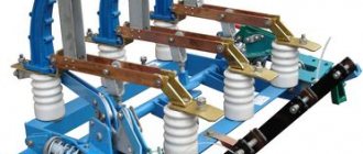
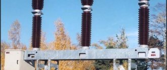
Let's look at what a load switch consists of using the example of a switching device type VNR-10/400
- Base (frame).
- Support insulator.
- Holders with contacts.
- Movable working knife.
- Arc extinction chamber.
- Fixed top contact.
- Isolating traction.
- Lever arm.
- Flexible communication.
- Grounding knife.
- Ground shaft.
- Locking device pull.
- Springs.
- Rubber gaskets.
- Shaft of working knives.
Operating principle
Let's take a brief look at how load switches work using the example of the above-mentioned VNR-10/400, shown in the photo:
Structurally, this switching device is similar to a disconnector. The main difference between a disconnector and a HV is that the latter has an arc extinguishing device and a drive, which ensures faster execution of operations.
The operating principle of the load switch is as follows. In the on position, the moving contacts are located in the arc chute. At the bottom of the arc extinguishing device there are additional arc extinguishing contacts. When performing a tripping operation, the main contacts are opened first, followed by the arcing contacts.
The electric arc formed during the breaking of the contacts enters the arc-extinguishing chamber, where it heats the plexiglass to a high temperature, which in turn releases a large amount of gases.
These gases burst out of the arc-extinguishing chamber in a powerful stream, thereby extinguishing the resulting electric arc in a few milliseconds.
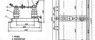
How is VN depicted on single-line diagrams? Below is a symbol in the diagram:
On the left in the diagram is a VN, on the right is a switching device, which is structurally equipped with fuses (VNP).
So we looked at the device, purpose and principle of operation of the load switch. We hope that the material provided was useful and interesting for you!
We also recommend reading:
Source: https://samelectrik.ru/chto-takoe-vyklyuchatel-nagruzki.html
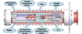
How the switch mechanism works
The load switch device consists of a frame and a shaft. Six support insulators are fixed to the frame. Of these insulators, three are fixed to the frame, in its lower part, on which the contact knives are located. The remaining contacts are installed on the frame at the top. They have main-purpose and arc-extinguishing contacts. To carry out movement to the contact knives, the shaft levers are connected to rods made of electrical insulating material.
At the end points of the shaft there are a pair of release springs. They speed up the process of disconnecting the circuit breaker at the moment of release of the system, where the drive is freely disengaged. In the same places, buffer rubber gaskets are installed to prevent mechanical shocks during shutdown.
In the arc extinguishing chambers, the process of disconnecting special arc extinguishing contacts occurs. The contact material is phenolic plastic with inserts based on glass-filled polyamide. The shape of the earbuds and the cameras themselves is arched. This design solution allows the arc extinguishing contacts to smoothly enter them.
In the process of switching on the circuit, first of all, the arc extinguishing contacts are connected, then the main contacts with the knives are closed. When the load is switched off, the whole process occurs in reverse order.
The position of the arc extinguishing contacts when the load is off is characterized by the presence of a visible air gap between them and the chamber, according to the principle of a conventional disconnector. At the moment of shutdown, an electric arc appears, and all this is accompanied by strong radiation of heat, heating the glass-filled polyamide. The latter forms a gas emission that extinguishes the arc.
Marking of load switches
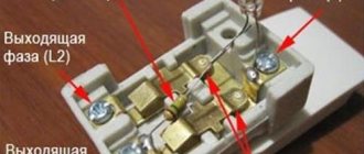
Each electromechanical device has its own marking, and the circuit breaker is no exception. The marking consists of letters and numbers that indicate the location of the drive, voltage, current and other characteristics.
For example, the designation of a 10 kV load switch VNRp 10/400-10зп stands for:
- B – switch;
- N – load;
- P – manual drive;
- P – built-in fuse;
- 10 – voltage 10 V;
- 400 – current 400 A;
- 10 – through current;
- Z – presence of grounding knives;
- P – arrangement of knives behind the fuse.
Other models are written in a similar way.
Load switches/switches in boxes
Load switches/switches in boxes are designed as main switches to isolate equipment from the mains. The range consists of load switches/switches, switches with fuses and changeover switches in plastic, metal and stainless steel boxes. Switches in boxes are designed for switching circuits under load. In addition, fused switches provide protection for equipment and cables from short circuit currents and overloads.
Plastic. Plastic boxes are suitable for use in high humidity conditions and resist various chemical influences. In addition, switches in boxes are relatively lightweight and easy to install and operate.
Metal. Metal boxes are galvanized and have a polymer coating, are durable and suitable for most conditions.
Made from stainless steel. The boxes are made of AISI 304 stainless steel. Switches in boxes are used, in particular, in the food industry, in the beverage industry, and also in conditions of high hygienic requirements. The boxes have an attractive appearance, do not require painting, and the smooth surface is easy to clean.
Types of high-voltage load switches
The types of load switches are as follows.
Autogas:
- BHA-10/630. This type of switch provides switching of three-phase electrical circuits for voltages of 6000 and 10000 V, the frequency of which is 50 Hz, under load. Automatic grounding of switched off lines is provided using special grounding knives. These device models are installed mainly at transformer substations, in distribution devices and in service boxes. The type of arc extinguisher is autogas; the drive can be either manual or electric. The units are designed for a twenty-five-year service life with intermediate overhauls every two thousand operations.
- VNB-10/630. The 10 kV high speed load switch is used in loaded circuits with current strength up to 630A. Its neutral wire is grounded or insulated. The units of application are one-way maintenance of stationary chambers, substations of transformer devices, complete distribution cabinets, they are also used to replace old modifications of switches. Arc extinguishing system using gas release.
- BHP-10/630. It works in a similar way to the BHA-10/630 switch, but the drive is only manual. Can be equipped with grounding contacts and additional fuses.
Vacuum:
- VBSK-10-20/1000. Load switches designed for voltages up to 12000 V, which are capable of switching electrical circuits (three-phase with isolated neutral) in normal operation modes and in emergency situations. The devices are used in all of the above systems, as well as when replacing low-oil switches. Switches of this type have small dimensions, therefore they are convenient for installation in different types of distribution boxes.
- BBTEL. A universal disconnecting device, the arc extinguishing system of which is based on its attenuation in a deep vacuum. The electromagnetic mechanism fixes the arc extinguishing contacts when closed. These systems are distinguished by their long service life and high wear resistance. They are small in size and do not require repairs.
- BBT-10-20. Vacuum type circuit breaker with motor-spring drive, which is designed for the same purposes as VBSK-10-20/1000, but this load circuit breaker can only withstand 10 kV.
Disconnect devices:
- RVZ-10/630 are designed for switching purposes when working with high voltage, but no load currents. Using them, you can reconnect and change circuits, and repair work is carried out in a safe mode (de-energized lines). They have a drive design of a lever operating principle.
- RLND - perform the same functions, but are acceptable for installation outdoors.
Read more: Screen for a bathtub made of tiles, methods and instructions for the device
Differences from circuit breaker
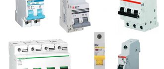
An automatic load switch is an electrical switching device. It is designed to conduct rated currents to the load and opens the circuit automatically if short circuit currents or currents exceeding the rated value occur. Also, some devices are capable of triggering when there is an unwanted decrease in the supply voltage when the power changes direction. Machines should not be used as toggle switches; their mechanism is not suitable for this; internal contacts may burn.
According to the number of pole contacts: one-, two- and three-pole.
With and without current limiting function.
According to the release mechanism: thermal from overloads, electromagnetic from short-circuit, semiconductor, adjustable from all accidents, combined.
Manual drive or from electromagnets.
With the ability to set a time delay in short-circuit mode. without this function.
By type of design: fixed, stationary and retractable.
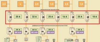
Automatic differential switch
At home, other devices are often used - automatic differential switches. They are installed on various household appliances to protect against power surges. They can de-energize the room if necessary, protect pantographs and wiring from the aggressive effects of high currents.
Circuit breakers are not suitable for frequent trips and shutdowns. This can lead to rapid wear of the module and burnout of the working resource, after which the device will have to be replaced. For such purposes, it is recommended to use modular load switches. Input switches ensure high safety of distribution boards, uninterrupted supply of electricity, and ease of circuit breaking. The best option is to use a load switch and a machine at the same time. This increases the security of the electrical network.
The main difference from an automatic machine is the inability to operate in automatic mode. Switching requires external intervention - manual or remote. The machine is triggered when the maximum current is reached. Also, devices may differ in markings and appearance.
How to choose a circuit breaker
It is believed that the most reliable version of a circuit breaker is a device that can withstand the maximum load and provide the room with the most effective protection. If you follow this logic, you can use air machines in any network, and thus save yourself from most problems, but in practice the situation is somewhat different. Depending on the parameters of a particular circuit, the type of switch that is best installed in it will also depend. If you choose the wrong circuit breaker, it can ultimately turn out extremely negatively.
If a device that is designed to operate under high-power conditions is connected to an ordinary household power supply network, it will not turn off the power even when the current significantly exceeds all permissible standards. In this case, the temperature of the insulating layer will increase significantly and become destructive for the cable, but the rated values of the switch will not be exceeded, so the machine will perceive this situation as ordinary. The shutdown will occur only after a short circuit occurs due to the melting of the insulation in the network, but this situation is already fraught with fire.
If the permissible power of the machine, on the contrary, does not reach that which the power supply line can withstand, it is almost impossible to achieve normal operation of the circuit. After connecting several devices, the electricity will immediately go out, and eventually, due to the constant exposure to high current, it will break due to “sticking” of the contacts.
Connection rules
On power lines, the device is installed in front of the transformer. In residential buildings, the switch is placed in the distribution panel or other place for each apartment separately. In the apartment itself, the switches are installed in front of the meter, but they can also be installed after the meter. Be sure to install the switch according to the diagram in front of other protective devices (plugs, circuit breakers).
In plants, factories and other production facilities, the switch is placed next to machines that may require emergency shutdown.
Load break switch selection
It must be remembered that all automatic load switches are designed to protect wiring from overheating, fire and burnout, and not electrical appliances. Therefore, in order to choose the right input disconnector, you need to know what current the cable or its cross-section is designed for. The operating current of the machine should be slightly less than the maximum permissible for the wire.
In the case when the cable capacity is much greater than the current consumption of the load, then you can select a machine for the load. To do this, sum up the power of all electrical appliances, adding the reserve percentage, and find the total current consumption based on Ohm’s law. Next, select an automatic machine whose operating current will be the closest to the calculated one.
Similar articles:
- Do-it-yourself heat pump for heating a house, device, operating principle of the circuit
- Ventilation grille with non-return valve types of device operating principle installation instructions
- Water flow switch device operating principle connection and adjustment
- Design and principle of operation of a water supply pumping station
Load switches/switches OT and OETL
Load break switches/switches - OT and OETL can be used for a variety of applications, ranging from remote control centers to switchboards and machine switches.
Due to their high technical characteristics, load switches are compatible with various distribution devices and can be installed anywhere in the electrical installation of AC and DC circuits. There are three options for installing the control handle: in front, between the poles or on the side of the switch.
Wide selection of accessories. Electrical and mechanical interlocking, a set of accessories for converting standard load switches into reversing and bypass switches, as well as parallel operating switches with three to eight poles, provide the ability to use standard switches for special applications. Cable clamps for connecting aluminum or copper cables without lugs; The use of cable covers ensures degree of protection IP20.