What is a pass-through switch and how does it work?
It would be more correct to call this device a switch - it is a switch for users rather out of habit, since it is used to turn lighting on and off. If you call it correctly, then it is much easier to understand how it differs from standard switches - this name most fully reflects the essence of its effect on a working electrical circuit.
Additional names are changeover, duplicate or cross switch.
Like a standard switch, a walk-through switch has only two positions, but the fundamental difference is that in a conventional device it is strictly defined, for example, up is on, and down is off, but with a walk-through, these sides are constantly changing.
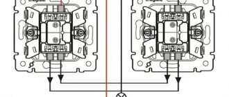
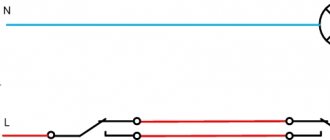
The operating principle of the pass-through switch becomes clearest when comparing the electrical circuits between it and the standard device, which is shown in the figure:
If a regular one in an open state simply breaks the circuit, then in the case of a pass-through one it all depends on the position of two switches at once:
From the diagram it is clear that each of the switches must have three terminals - one for the phase that comes from the power source and two for the “control” wires. When either of the two switches changes position, the circuit either closes or opens, depending on what state it was in before.
Additionally, we can formulate one more difference between a switch and a switch - the latter can always be connected as a simple switch, but doing the opposite will not work. When repairing such a circuit, it must be taken into account that one of the wires between the switches is always live.
Types of switches and their designation in diagrams
Products can be divided into different groups depending on the design and features of use. Main options:
- Mechanical are the simplest and most reliable devices in which the circuit is closed and opened by pressing a key.
- Semiconductor , sensor options are most common. They are activated by the touch of a finger and look modern. There are also models with a remote control; they are convenient because you can control the light from anywhere in the room.
Based on the number of independent loads controlled by the switch, 2 types can be distinguished:
- Single-line . The simplest devices with one key.
- Multilinear , they can have 2 or more keys.
Cross models are a type of pass-through switch, so they also belong to the equipment group under consideration.
As for the designation on the diagrams, all options are shown below. It is not difficult to distinguish a pass-through switch from a standard one.
A symbol with projections on both sides indicates a pass-through switch.
Selection, design and differences of pass-through switches
Before assembling such a control scheme, here is what you should pay special attention to:
- To connect a pass-through light switch, a three-core cable is required - VVGng-Ls 3*1.5 or NYM 3*1.5mm²
- Do not try to assemble a similar circuit using ordinary switches.
The main difference between regular and pass-through ones is the number of contacts. Simple single-key ones have two terminals for connecting wires (input and output), while pass-through ones have three!
In simple terms, the lighting circuit can be either closed or open, there is no third option.
It is more correct to call a pass-through not a switch, but a switch.
Since it switches the circuit from one working contact to another.
In appearance, from the front they can be absolutely identical. Only the pass key can have an icon of vertical triangles. However, do not confuse them with reversible or crossover ones (more about them below). These triangles point in a horizontal direction.
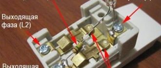
But from the reverse side you can immediately see the difference:
- the pass-through has 1 terminal on top and 2 on the bottom
- a regular one has 1 on top and 1 on the bottom
Due to this parameter, many people confuse them with two-key ones. However, two-key ones are also not suitable here, although they also have three terminals. The significant difference is in the operation of the contacts. When one contact is closed, pass-through switches automatically close the other, but two-key switches do not have such a function. Moreover, there is no intermediate position when both circuits are open at the gateway.
Diagram of pass-through and cross switches
One of the oldest and most proven schemes is the method of using pass-through and crossover switches. The price of such switches is not that high, and the connection diagram, although it seems very complicated at first glance, should not cause you any problems.
Through and cross switches
But before moving directly to the connection diagram, let's figure out what these pass-through and crossover switches are, and how they differ from the lighting switches we are used to.
| To make things easier to understand, let's look at a regular switch. It has two contacts, let's call them 1 and 2. When the switch is in the on position, these contacts are closed. When the switch is turned off, these contacts open. |
| Now let's take the pass-through switch. It already has three contacts - 1, 2 and 3. When the switch is in the on position, contacts 1 and 2 are closed. Contacts 1 and 3 are open. When such a switch is turned off, contacts 1 and 2 open, and contacts 1 and 3 close. |
| Cross switch diagram | As you probably already guessed, the crossover switch already has four contacts - 1, 2, 3 and 4. In the on position, contacts 1 and 3, as well as 2 and 4 are closed. When the switch is turned off, they open, and contacts 1 and 4 are closed, and also 2 and 3. |
Note! Such switches can operate at a rated network current of 6, 10 or 16A. In this case, all switches in the circuit must have the same or greater rated current. And the wires used during installation have the same cross-section.
Connection diagram for pass-through and cross switches for lighting control from 4 places
Having an idea of the design features of such switching devices, you can begin to consider their connection diagram. By the way, it is correct to call such switching devices not switches, but switches.
Switch installation
So:
- Any lighting control from 4 places requires the installation of four switching devices. Cross and pass-through switches for hidden wiring are installed in ordinary embedded boxes. You choose their installation locations based on expediency.
- Pass-through switches must be the first and last in the circuit. Therefore, they are mounted at extreme points.
Connecting a pass-through switch
- Now let's proceed directly to the connection. Let's start by connecting the first pass-through switch. From the distribution box, as with a regular switch, you take a phase wire. It should be connected to pin one. Usually it can be determined visually.
- From the other two contacts of the first crossover switch, you install a two-wire wire to the first crossover switch. This can be done through a connection in the junction box, or by connecting directly to the switch contacts. They should be connected to pins 1 and 2, as in the video.
Note! Our designation 1 and 2, 3 and 4 is very arbitrary. Each manufacturer independently designates pairs of contacts. But usually one pair of contacts is located in the upper part - conventionally 1 and 2, and the second pair of contacts - 3 and 4 is located in the lower part.
- From pins 3 and 4 of the first crossover switch, we run a wire to pins 1 and 2 of the second. From pins 3 and 4 of the second crossover switch, we run a wire to pins 2 and 3 of the second pass-through switch.
Connecting the cross switch
- Now all that remains is to connect pin 1 of the second crossover switch to the lamp. That's it, connecting the switches is finished. All that remains is to connect the neutral and protective wires to the corresponding contacts of the lamp - and our circuit is ready for use.
Four-place lighting control circuit
As you can see, connecting this circuit is not particularly difficult, and it can be done with your own hands. At the same time, when installing the entire circuit through one junction box, even experienced electricians can get confused.
And a large number of contact connections does not add reliability to the circuit. Based on this, recently this scheme has been used less and less. After all, there are simpler options.
Advantages of installing a pass-through switch
Pass-through switches allow you to control room lighting from two or more places, which is an undeniable convenience. This is especially valuable for multi-story houses with flights of stairs. Here you can install the first switch on the first floor and the next on the second, which will turn on the light downstairs and turn off the upstairs.
The use of walk-through switches to control the lighting of staircases is especially important. A good solution is to install one switch at the entrance to the bedroom, and a second near the head of the bed, which will allow you to enter, turn on the light, get ready for bed, lie down and turn off the light. It is also advisable to install switches at the entrance to a house or apartment and at the end of the corridor.
Helpful advice! Using special motion sensors or a timer built into the switch, you can automatically turn off the lighting when leaving a certain place.
Walk-through switches have significant advantages compared to conventional devices:
- high reliability and safety of operation;
- instant shutdown of the power supply to the premises, if necessary, from any point;
- optimal energy consumption;
- low cost;
- simple installation that does not require the involvement of specialists;
- no complicated settings.
The presence of walk-through switches allows you to turn on the lamps below with one switch, and when going up the stairs, turn them off with another
What is a staircase switch? And what are the benefits of installing it in your home?
This is a mechanism consisting of two switches, one of which is installed on the first floor, and the second on the second floor. Together they allow you to control the lighting of the staircase from several places at the same time. This way, you can turn the staircase lights on and off anywhere - both on the first and second floors. So this is a very practical solution that will make your home more comfortable.
In fact, it's not even a switch, but a switch connector. This device got its name “staircase switch” because it is most often installed to control staircase lighting. However, it can also be used in other areas of the house where you plan to control lights from multiple places at once, such as a long hallway, a large bedroom with two exits, or a bathroom.
Connection diagram for the pass-through switch wires in the distribution box
Circuit without grounding conductor.
Now the most important thing is to correctly assemble the circuit in the junction box. Four 3-core cables should go into it:
- power cable from lighting circuit breaker
- cable to switch No. 1
- cable to switch No. 2
- cable for lamp or chandelier
When connecting wires, it is most convenient to orient them by color. If you use a three-core VVG cable, then it has two most common color markings:
- white (gray) – phase
- blue – zero
- yellow green – earth
or second option:
- White gray)
- brown
- black
To choose a more correct phasing in the second case, follow the tips from the article “Color marking of wires. GOSTs and rules.”
- The assembly begins with neutral conductors. Connect the neutral conductor from the cable of the input machine and the neutral going to the lamp at one point using the terminals of the car.
- Next, you need to connect all the grounding conductors, if you have a grounding conductor. Similar to the neutral wires, you combine the “ground” from the input cable with the “ground” of the outgoing cable for lighting.
This wire is connected to the lamp body. - All that remains is to connect the phase conductors correctly and without errors. The phase from the input cable must be connected to the phase of the outgoing wire to the common terminal of the pass-through switch No. 1.
And connect the common wire from pass-through switch No. 2 with a separate wago clamp to the phase conductor of the lighting cable.
Having completed all these connections, all that remains is to connect the secondary (outgoing) conductors from switch No. 1 and No. 2 to each other. And it doesn’t matter at all how you connect them.
You can even mix up the colors. But it’s better to stick to the colors so as not to get confused in the future. At this point, you can consider the circuit fully assembled, apply voltage and check the lighting.
The basic connection rules in this diagram that you need to remember:
- the phase from the machine must go to the common conductor of the first switch
- and the same phase should go from the common conductor of the second switch to the light bulb
- the remaining two auxiliary conductors are connected to each other in the junction box
- zero and ground are supplied directly to the light bulbs without switches
Features of the pass-through switch
Unlike a conventional double switch, a pass-through switch has three contacts. These devices are connected to each other via a three-core cable, which can run openly from the outside, or can be hidden inside the wall in a grooved groove.
The connection is made in such a way that the neutral wire goes to the light source, and the phase goes into the electrical circuit open to the switch. The neutral cable goes through the power distribution box to the lamp, the phase cable goes to the input.
Two cables are connected to the output, and the electrical circuit is alternately closed using a jumper. These wires are connected to the second switch, and one of them goes further to the lamp. Thus, electricity is transferred from the first line to the second.
Such a device as a triple pass-through switch is available for free sale today, but its cost is quite high. And if you don’t want to overpay a lot of money, you can make a pass-through switch with your own hands. This does not require any special tools or any special professional skills.
Externally, a pass-through switch is indistinguishable from a regular one, and may have one or more switch keys. The difference between them lies in the internal structure. At home, main switches with one key are usually used. However, it is more correct to call a transition device a switch, since it is designed to switch electrical circuits. If the room is large, you may need a device with several keys.
What to buy to implement the scheme
Understanding how a pass-through switch works, you can independently install a convenient lighting control circuit. Products from several companies are popular on the electrical goods market, for example legrand pass-through switches. They are functional, have an attractive design, some with LED backlighting.
The legrand valena pass-through switch, if it is without a pair, can work as a simple one. But usually they are bought in pairs.
Buyers often ask how a pass-through switch looks different from a regular one. There are few differences: enterprises use a single housing design for different devices. There is no marking on the pass-throughs indicating switching on (sometimes there is one, due to the use of standard components, but they do not pay attention to it). Differences in the connection of electrical contacts can be easily determined by a person familiar with electrical engineering.
The figure shows the connection of a pair of legrand pass-through switches operating for one group of lamps.
Pass-through switches, like regular ones, are available with one or two keys. Two-key controls control two groups of lamps. You can, for example, adjust the brightness of the lighting by turning on and off groups of light bulbs in a chandelier. No worse than products from other companies: lezard, lexman, abb, schneider electric. Lezard pass-through switches are connected in the same way as those made by legrand and other companies.
It is very simple to assemble a circuit from devices from any manufacturer, but sometimes difficulties arise because circuits with errors are found on commercial sites on the Internet. Sometimes cheap Chinese devices are accompanied by paper instructions with errors in the circuits. Use the simplest diagram on which everything is clear and which you understand.
Connection diagrams
Schemes of pass-through switches differ in the number of connection points. The easiest to implement is the option with two control points for the device, but more may be required.
If you have experience or a sufficient knowledge base about the process of connecting a conventional switch, there will be no difficulties with this type of connection. Here the principle of operation is the same, except for more wires and terminals. In the case of a conventional design, there are two, while the one under consideration has three.
A three-wire type of wiring runs from the junction box to this switch. Moreover, its cross-sectional size must be selected to match the power of the controlled device.
Well-known manufacturers of pass-through switches
The Legrand company occupies a leading position in the electrical goods market. The demand for Legrand pass-through switches is due to the high quality of the products, ease of installation, ease of further operation, stylish design and flexible pricing policy. The only drawback is the need to adjust the installation location. If it does not coincide with the product, difficulties may arise during its installation, which is carried out according to the connection diagram for the Legrand pass-through switch.
A subsidiary of Legrand is the Chinese company Lezard. However, the products have only a stylish design left from their native brand. The build quality is much lower, which is due to the low cost of the products.
One of the leading domestic manufacturers of electrical goods is the Wessen company, which is part of the Schneider Electric company. All products are manufactured using the latest technologies on modern foreign equipment and comply with European quality standards. The models have a universal, stylish design that allows each element to fit into any interior of the room. A distinctive feature of Wessen switches is the ability to replace the decorative frame without dismantling the device.
Another equally well-known manufacturer is the Turkish company Viko. The products are characterized by high quality workmanship, reliability and durability, and comply with electrical safety requirements and European quality standards. In the manufacture of the device body, fireproof durable plastic is used, which is designed for a large number of operating cycles.
A pass-through switch, unlike a regular switch, has three conductive wires. The Turkish brand Makel offers high-quality, reliable, safe and stylish products. Thanks to the ability to connect a cable without the need to use a distribution box, installation of switches becomes simpler, and further operation becomes comfortable and safe.
Connecting switches with two control points
According to the connection diagram, the following are installed in the junction box:
- three-core cable from two pass-through control devices;
- two-wire cable from the controlled device;
- two-wire network cable.
Inside the distribution box, the connection starts from the phase wire of the distribution box. It is connected to the input contact of one of the control devices.
Next, you need to take care of how to properly connect the pass-through switches to each other. The two remaining contacts connected to the box phase are connected to similar ones from the second device.
The remaining common contact of the second device is combined with the cable of the electrical appliance. The second wire of the controlled device is connected to the neutral contact of the distribution box.
How to make a pass-through switch with your own hands
Despite the fact that at first glance, regular and pass-through switches have minor differences, their cost is significantly different. You can buy a pass-through switch 1.5-2 times more expensive than a simple switch. Therefore, many craftsmen strive to make a switching device themselves.
To get a pass-through single-key switch, you need to use conventional single-key and two-key devices of the same size and manufacturer.
Helpful advice! When purchasing a two-key pass-through switch, the diagram of which is printed on the body of the device, you should make sure that it has the ability to move the terminals in places in such an order as to ensure that the circuit is broken and closed independently of each other.
The process of converting a simple switch into a walk-through switch consists of the following steps:
- on a surface-mounted single-key switch, the key equipped with clips is removed;
- the switch core is carefully squeezed out;
- the housing clamps on the internal mechanism of the switch are pressed out;
- one of the terminals is removed from the socket;
- one contact is reinstalled opposite the other;
- a rocker arm is installed on the contacts;
- the body is put back together.
Using pass-through switches will be convenient if the house has long corridors
You can also assemble one switch from two simple ones. They should be placed next to each other so that when the top part of the key is pressed, one is activated, and the bottom – the other. The keys should be connected with a plate that is glued on top. It is imperative to install a jumper between two adjacent contacts.
Types of switching devices
Switches differ from each other in several ways. In order to choose the appropriate option, you need to familiarize yourself with them in more detail - we will present the necessary information in the form of a table.
Table No. 1. Types of switches.
| View | Description |
| Push-button | As a rule, such a device is suitable for call control, so it is installed near the entrance. However, it is not used to control luminaires. |
| Keyboards | This is a standard option that is used to open and close circuits in household electrical networks. |
| Rotary | Such switches are also sometimes installed in residential premises, but most often they can be found in production. After all, they do not have such an aesthetic appearance as the previous options. |
As we have already said, there are single-key devices, as well as two-key and three-key devices. They, in turn, are divided into standard, combined type and intermediate devices.
In the first case we are talking about three-pin switches, in the second the number of clamps differs in the number of keys. The third option is intended for complex circuits where it is necessary to organize more than two switching points.
In private houses or apartments in multi-story buildings, devices with keys are often installed
Sometimes devices are mounted with touch control or remote control. The third option has gained popularity in recent years.
Important. In addition, there are switches with a motion sensor. This is a combined electrical device that responds to movement in a certain area. Such switches are installed both in residential premises and outdoors. After all, this provides additional security. You can read about how to connect a motion sensor in our special article.
According to the method of laying electrical wiring, switches are divided into the following types:
- external (surface switches);
- built-in (hidden).
In the first case, you will need to attach the device directly to the ceiling with screws. The second option involves a fastening method using special lugs that are located at the edges.
Prices for pass-through single-key switches
Single-key pass-through switch
Video - Pass-through switch or impulse relay?
If you need to choose the optimal switch option if you have a pass-through device circuit, then you should correctly determine the number of keys (each group of devices must have one key). If you are going to organize only two points to control the lamp, then purchase a standard switch with three contacts. If a larger number of points is required, you will have to purchase additional devices to connect to the common chain.
Most often, devices with a key have only two positions - on and off. However, equipment is commercially available with an additional central position (zero), which is designed to open these two circuits.
Designations on the device body
On the body of the switching device, where the contacts are located, there is usually a marking with the characteristics of the device. The voltage, rated current and degree of protection of the product are indicated here.
Switches
For standard light bulbs, you must choose a device marked “A”. If you plan to install gas light lamps, then you should choose a switch marked “AX”.
When the light in gas lighting fixtures is turned on, a sharp fluctuation in inrush currents occurs. When installing standard bulbs and LED bulbs, the fluctuation will not be so pronounced. It turns out that the switch must be designed for such a load, otherwise the possibility of melting of the contacts in the terminals cannot be ruled out. Therefore, in the case of gas light lamps, an appropriate device is required.
Important. Of no small importance is the degree of protection of the device - IP. If you plan to install the device in the hallway or bedroom, then the degree of protection - “2” is sufficient. If you need to install the switch in a room with high humidity, then protection up to “55” is required.
The terminals for fixing electrical wiring also differ from each other:
- on screws with a pressure plate;
- without screws with spring.
The first fixation option is considered durable, and the second is easy to install, which is why switches with screws and a pressure plate are popular - when fixed, they do not violate the integrity of the conductor core.
If the wire has a diameter of one and a half millimeters, then a switch with screws is not used to connect it
In addition, on the device body there are clamp designations:
- “N” – for neutral wire;
- “L” – for phase wire;
- “ground” – for the grounding conductor.
In addition, there are other markings on the device - this may be the value of opening and closing the circuit, the manufacturer’s logo.
Prices for walk-through two-key switches
Two-key pass-through switch
What limits the number of pass-through switches
A chain of switches that allows switching electric current from several points should not be too cumbersome. The contacts resist electric current. It is small, but over a long chain of contacts the current can decrease noticeably.
With a large number of switches connected one after another, the reliability of the circuit decreases and failures are possible. Therefore, we rarely see a string of pass-through and crossover switches of ten or more pieces. Most often this is a pair of switches, somewhat less often - a chain of three, four, five.
New technologies: touch pass-through switches
Stylish touch switches are more expensive than regular ones, but they are in demand - they have become a natural part of modern “digital culture”. Touch devices are quite complex electronic devices. A high-power thyristor or transistor is used to switch the current, and the signal that opens (or locks) the device comes from a sensor - a sensor that responds to some external influence.
The sensor can be a motion sensor, or an acoustic one, or a capacitive one that responds to touch. Sensitive sensors react even before touching, just bring your hand to a distance of 1-3 centimeters. Homes usually install capacitive touch switches, or those combined with a motion sensor. All touch devices can be controlled remotely. If the control panel is not included, it must be purchased separately.
The semiconductor device responsible for turning the current on and off can also be used to control the current strength and brightness of the light, if equipped with a dimmer. It is important to know that dimmers are not suitable for all lighting fixtures.
The photo shows a touch switch.
Pass-through and cross touch switches, like mechanical ones, are used to control lighting fixtures from different points. Compared to mechanical ones, they are more functional: they can be controlled remotely and control the light intensity.
Externally, touch devices are a smooth glass panel; when connected, there is a visible indication on it: blue firefly - OFF, red - ON. To control the lighting device, you just need to touch the device panel.
Lighting control from three places or more
There are often situations when in large residential premises there is a need to control lighting from several points at once. To create a multi-point control system that allows you to turn on and off lights from 3 places at the same time, installing pass-through switches alone is usually not enough.
For these purposes, it will be necessary to integrate one more element into the circuit - a crossover switch, which is connected at the break of the two-core wire (that is, between the pass-through devices).
If in earlier times the permissibility of installing such schemes was determined mainly by the layout of the premises, today they are found almost everywhere. Installing pass-through switches of this type is not an easy task. First of all, you need to familiarize yourself with the principle of its operation.
Operating principle of a cross switch (switch)
The design of the switch provides for the presence of four contacts, of which two are connected to the terminals of one switch and two more to the second device.
Please note: The main difference between crossover switches and pass-through switches is that they can only be used in conjunction with pass-through switches.
When switched on in this way, these devices perform special (transit) functions, since they are to a certain extent transitional.
You can clearly see the principle of operation of the cross switch in the GIF picture below.
Connection diagram for three switches
A schematic diagram of connecting a 2-way switch and one crossover switch is shown in the figure.
It clearly shows that a cross switch is installed between the two pass-through switches, acting as a kind of transit node.
Below we provide a diagram of the connection of all elements of the electrical lighting control chain in the junction box.
The video that we have posted below will undoubtedly help you assemble a wiring diagram for three switches in a junction box.
Connection diagram for four switches
For four control points, you will need to use the complex wiring diagram shown in the figure below. This kit uses not only two pass-through switches, but also a pair of cross-type switches.
When considering the option of controlling a lamp from 4 places at once, two cross switching devices will be required.
If there are several lighting groups in a given room, preference should be given to two-key cross-type switches. Passage systems installed in this way significantly simplify the lighting control procedure.
Additional information: To control their lighting fixtures from many points, the apartment owner can use both key switches and motion or sound sensors.
These systems of many switched devices (for all their apparent convenience) raise doubts about their reliability to an even greater extent. Even if they are turned on correctly and handled with care, they are characterized by the following disadvantages:
- relatively high cost;
- relatively low reliability;
- possibility of false positives;
- difficulty of maintenance and repair.
That is why connecting pass-through and cross switches to control lighting from several places is the best option for using the principle of multipoint control.
Connection diagram for a two-key pass-through switch
Using pass-through switches, you can control not only one lamp, but also a group of several lighting fixtures. To do this, connect pass-through two-key switches. Each of them has six contacts. Common wires are determined according to the same principle as for conventional devices, but a larger number of wires need to be wired.
The difference between the double pass-through switch wiring diagram is that more wires are used here. The phase is supplied to both inputs of the first switch. Wires should go out from the two inputs of the second switch to two lamps. In the case of organizing lighting control from three or more points, two cross switches should be installed for each of them, since they are only available as single-key switches.
Connection diagram for a pass-through two-key switch
In this case, according to the principle of connecting double pass-through switches with crossover switches, the first pair of contacts should be connected to one crossover, and the second to the other. If necessary, the devices are connected to each other. The output of both crossover switches must be connected to the last two-key transfer device.