What is a pass-through switch
A pass-through switch is a device designed to turn on one light source from different points in the apartment. Electricians call such a device a switch, because this largely reflects its functions. Other names are “changeover”, “crossover”, “marching” or “backup”.
The main difference is the presence of more contacts. For example, if a conventional device has two contact connections, a transitional device has three. Two of them are common, which ensures that the light bulb turns on from different places, for example, at the beginning and end of the room.
Design and operating principle
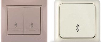
Externally, the pass-through switch is no different from a regular one.
But still it has distinctive features:
- the button shows two arrows (up and down), which are located on top of each other;
- three contact groups - one input and two outputs;
- three-wire switching, providing voltage redirection between contact groups.
To control one light source, two pass-through switches are required.
The operating principle is as follows:
- a neutral and phase wire are supplied to each switching device;
- moving the key to another position causes voltage to be supplied to the light bulb;
- When either of the two switches is turned off, the power circuit is broken and the light source goes out.
Switching on and off is possible not only from two, but also from a larger number of points. To do this, you need to add one or more redundant switches.
Design of a pass-through switch and difference from other types
Externally, a pass-through switch does not differ from a household device designed to control light. It is equipped with one, two or three movable keys, each of which has two independent fixed positions. The fundamental difference from conventional switching devices is in the design of the contact group. If a standard device has one pair of contacts for each key for closing and opening the circuit, then in a pass-through switch each movable panel controls a changeover contact group. In one position one circuit is closed, in the other - another. In fact, such a device is a switch.
Switch 2 has two contact groups that can be controlled independently. Three-key, respectively, three. To distinguish a walk-through device from a regular one, it is often marked in the form of arrows or a symbolic designation of a flight of stairs.
Two-key pass-through device with markings in the form of a ladder.
Important! Do not confuse pass-through switches with crossover switches. Such switching devices also have a system of switching contacts. The difference between crossover devices and two-key pass-through devices is that in the former, one key simultaneously controls two changeover contact groups. Another difference is in the internal layout. The normally open (normally open, NO) and normally closed (normally closed, NC) contacts of each pair of such a device are cross-connected. Such devices are also used in lighting control schemes from three or more points.
According to their design, pass-through devices are:
- invoices (for open and hidden wiring);
- built-in (for hidden wiring).
There are also touch switches, but they are more expensive. In addition, most users agree that they are less convenient.
Internal diagrams of conventional and pass-through switching devices.
Where can I install
The changeover switch can be installed in any room. Most often it is installed in the following places:
- Landing. March switches are installed on several floors to control general lighting. For example, a resident of a house can turn on the pass-through switch at the entrance to the entrance, and when he goes up to the third floor to his apartment, turn off the light. You can proceed in a similar way when descending from top to bottom: first turn on the light bulb with a duplicate switch, and then turn it off at the bottom.
- Corridor. If there is a long corridor in an apartment or house, a pass-through switch is installed at the end and at the beginning of the room. So, when you start moving along the corridor, you can turn on the light, and when leaving it, turn it off.
- Bedroom. A convenient option is to place switches at the entrance and near the bed. In this case, you can go to bed and not get up to turn off the lights. This is especially important in a children's room so that the child does not have to walk through the entire room to turn on / off the lighting.
In practice, other methods of connecting such switches to a light bulb can be used. The main thing is to understand the principle of operation and determine the need to install the device. Most often this is done for convenience and/or energy savings.
What is a pass-through switch: differences from standard devices and purpose
A superficial study of the problem will not allow you to draw the right conclusion. To some, such devices seem unnecessary. However, similar arguments can be made against the use of remote controls and other devices to increase the level of comfort. Meanwhile, the transition switch is not only intended for convenience. What it is is shown in the following figure:
Functional diagram
The first picture shows a typical situation. One lamp is sufficient to illuminate a flight of stairs. It is turned on from the lower platform. Having risen to the upper platform (Picture No. 2), the electrical circuit is opened. This action is performed using another switch. When moving in the opposite direction, a similar algorithm of actions is used.
It is clear that such solutions significantly increase the level of security. They are used not only on stairs, but also in long corridors. Good lighting is especially important when there are turns, furniture, and other obstacles along the route. Such equipment is necessary if there are no windows. Modern users will be reminded of the presence of devices that perform similar functions using motion sensors and sounds.
Such a device can be installed discreetly, inside the lamp
A careful comparison with a pass-through switch will reveal the following disadvantages:
- Motion sensors have a specific directional pattern, which makes it difficult to choose a suitable place to mount it.
- The sound recorder is capable of detecting extraneous noise. Sensitivity should not be reduced excessively to maintain performance.
- These devices are sensitive to voltage surges. Some false alarms occur when over-the-air (network) electromagnetic interference occurs.
- Such products are more expensive than pass-through switches.
- Due to their increased complexity, they are designed for a shorter service life.
The listed arguments are sufficient for correct conclusions. Without diminishing the importance of modern solutions, it should be noted the real advantages of cheap, reliable and durable walk-through switches. Separately, it should be noted that the ergonomic indicators of residential premises are improved with the help of these relatively simple electrical products.
In the bedroom – the general light can be turned on at the entrance and turned off without getting out of bed
To increase free space, the living room is often combined with a kitchen, dining room and hallway. Using pass-through switches, it is not difficult to organize convenient lighting in each zone and supply power to a chandelier common to the entire room.
These devices will be useful when equipping recreation areas and other parts of the local area.
Expert opinion
Igor Marmazov
ES, EM, EO design engineer (power supply, electrical equipment, interior lighting) ASP North-West LLC
Ask a specialist
“We must not forget that for installation outdoors, purchase electrical products with a high class of protection from adverse atmospheric and weather influences.”
Single key switch
Pass-through switches (1 and 2) in the lighting lamp control circuit from two places
The above diagrams explain how a switch is different from a switch. The first one breaks and connects an electrical circuit. The second one changes the path of electric current.
Advantages of pass-through switches
Duplicate switches have a number of positive qualities that make them stand out among conventional devices.
Pros:
- Controlling one light source from different parts of the room.
- Safety of use.
- Easy to install and configure.
- Low cost and, as a result, low price.
- Saving electricity.
- Reliability in operation.
- Possibility of installation by yourself without the involvement of a specialist.
Connecting pass-through switches: step-by-step instructions
The use of pass-through switches makes available equipment for lighting networks consisting of one or more lines and controlled from two or more points . Each connection option will be considered schematically and described step by step, which will allow the user to evaluate the advantages of this connection system and make the switching independently.
| Advantages | Flaws |
| Ability to control from multiple locations | The need to use additional devices |
| Availability of connecting multiple lines | Complexity of installation and switching |
| Convenient control over long distances | |
| Energy Saving |
Flaws
Such switches also have a number of disadvantages that must be taken into account during installation.
Let's highlight the main ones:
- If you don't know the main differences, they can easily be confused with a regular switch.
- There is no precise position to detect the position (on, off). For example, when replacing a light bulb, it is difficult to understand whether the power supply to the device is suitable or not. For safety, it is recommended to turn off the power supply.
- There are many wires appearing in the junction box. Their number increases with the number of light bulbs. It is not advisable to connect devices directly, because in this case you will have to endure high costs. In addition, with a large number of lamps in one circuit, the use of pulse relays is provided.
- Higher price due to design features.
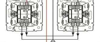
General connection principle
In Fig. 2 shows the general connection diagram for a two-key pass-through switch. Why common? Because the structure may be different (depending on the manufacturer) and the connection sequence may be slightly different.
As you can see, the neutral cable is immediately connected to the lamps. The phase electrical wire, in turn, is connected to the second device. It is connected to keys 1 and 2. Key 1 will close one of the two contacts. Two wires are connected to them. The same electrical wires must be connected to the contacts that will be closed by key 1 of the second disconnector. Next, an electrical wire extends from it to the first lamp. By analogy, wires are connected to keys 2 of the first and second switches.
There is nothing complicated here. However, the number of cables that are routed into the junction box is growing, and as a result, when installing a double pass-through switch, you need to be very careful to make the correct connection and avoid mistakes.
Otherwise, the lighting system will not work.
Helpful advice: using walk-through two-key devices to turn on the light will still take some getting used to. The thing is that they don't have on and off.
This means that the keys do not have fixed positions at which the light will be turned on or off. For example, in conventional devices for turning on the light, the upper position of the key means that the light is on, the lower position means that the light is off. In our case, the top position can be responsible for both turning on and off the light.
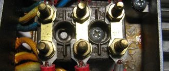
Practical connection diagram
Now let's look at a practical diagram for connecting double pass-through switches. The basis for the example will be the Legrand product. The diagram is given below.
Connecting Legrand switches as feedthroughs
The image shows that a phase cable is connected to both devices. If you look closely, you can see two keys in the middle of one device: left and right. In the first switch, current is supplied to the left key, in the second - to the right key.
Actually, from the very beginning you should make the connection of the phase wires.
Further in the picture you can see that both switches are connected by four intermediate electrical wiring.
Helpful tip: to avoid confusion, you can use wires of different colors. So, to connect the lower terminals 2 and 3 of both switches, you can use blue and red wires, and to connect the upper terminals 1 and 2 of both disconnectors, you can use brown and yellow wires.
The choice of colors is up to you. Thanks to this, you will make the correct connection of electrical wires in the junction box. At the end, all that remains is to connect the electrical wires that will supply power to the lighting fixtures. They are connected to the third upper contact on the left switch and to the first lower contact on the right device.
Now you know about the features of the switch release circuit, which is a pass-through and two-key switch, and you also know how to connect the switch itself.
In general, the connection process involves the following steps:
- Connecting phase wires.
- Connecting intermediate electrical cables.
- Connecting output electrical wires.
- Connecting the neutral electrical cable to the lamps.
Necessary tools and materials
In order to implement the connection process, you need to use the following tools:
- screwdriver for flat and figured slots;
- mounting knife for stripping electrical wires;
- side cutters;
- level;
- wrenches (necessary for mounting some chandeliers);
- pliers.
As for materials, you need to have terminal blocks for connecting cables in the junction box and electrical tape, as well as the double switches themselves. Also watch the video, which will tell you about the features of the connection diagram for a two-key pass-through switch:
Is it necessary to provide protection for pass-through switches and ground the lighting circuit?
The requirements of PUE, PTE and SNiP clearly state that lighting networks must be protected using a 6-10 Ampere “automatic machine”. Among manufacturers, it is recommended to give preference to ABB, Schneider or Eaton. Taking into account the above, it is mandatory to install a machine with optimal current in each distribution panel.
As for grounding, it is necessary to study the rules of the Electrical Installation Regulations (Chapter 1.7). The book says that the grounding of current-carrying and metal conductors to which voltage can be applied must be grounded. This means that the room must have grounding to ensure the required level of safety.
See how to choose a circuit breaker here.
Connection diagram
When installing a pass-through switch, you can use one of numerous schemes. They differ in the number of points and the number of switches on the device. Let's look at each connection option in more detail.
IMPORTANT: you need to use two or three-wire cables.
From two places
This connection scheme is good when living in a 2-story house, if you have a large room or a long corridor. Alternatively, it can be used in the bedroom when the lights are turned off near the head of the bed.
The principle is simple:
- Connect the ground and neutral wires to the lamp.
- Apply the phase to the input of the first pass-through switch, and direct the phase wire from the input of the other switch to the lamp.
Pressing any of the devices breaks the circuit and turns off the switch. Similarly, moving the key to the second position closes the chain and lights the lamp.
Diagram of connecting wires through a junction box.
When laying the wire, be guided by the current requirements. The wire should be about 150mm from the top. For installation, grooves and mounting trays/boxes are used.
Schematic diagram of the connection using the example of two switches.
The working principle of the circuit is shown below.
Three-seat control scheme
Undoubtedly, this is a disadvantage of such a system. See also:. Disconnect the apartment or house from power. For example, in a three-story house, on each floor you can control the lighting on the stairs where needed.
Install decorative device panels.
The procedure for installing a circuit with two-key pass-through switches Both switches are installed in socket boxes in the walls, two three-core contact cables are supplied to each of them, because 6 A three-core cable is also supplied to each lamp The ends of the cables are connected inside the junction box according to the connection diagram As you can see, there is absolutely nothing here complex. Install decorative device panels.
A phase is supplied to the first pass-through two-key switch, and then according to the diagram and instructions on the switches themselves. Picture 1.
Since there will be four connected wires in the junction box. To avoid this, the lighting in the hallway is turned off with a timer.
If your wiring goes under the ceiling, you will have to lower the wire from there to each switch, and then lift it back up. In general, the thing is convenient and necessary. However, a switch with three terminals will no longer work here. 2 key pass-through switches from 3 places connection diagram
Which cable is better to use?
According to current rules, when connecting a backup switch, it is recommended to use a 3-core copper cable with a cross-section of 1.5 square meters. mm.
The most popular options:
- VVGnG-3x1.5.
- ShVVP-3x1.5.
- PVSng-3x1.5.
The main difference between the above conductors is the type of insulating coating and the characteristics of the cores. When choosing a cable, make sure that it is marked according to GOST.
This guarantees that when purchasing a wire with a cross-section of 1.5 sq. mm you get exactly this parameter, and not 1.0 or, for example, 1.2 sq. mm. Remember that a mismatch in cross-section can lead to overload and accident.
Comments:
Victor
Yes, you can break your head before you connect it! At the same time, how to use it is not entirely clear, and the scope of application is not yet clear to me. Can anyone explain in what places this switch can practically be used?
Stas
Victor, my friend had ceiling lighting and kitchen lighting connected to such switches. True, my friend could not explain to me why he needed this. So the question of whether it is advisable to bother remains.
Slavik
Maybe I've been doing something wrong all along? The diagram in the video shows how to connect the lamp to ground. I have not seen grounding terminals on any chandelier. What's the catch? Is it possible that when connecting a pass-through switch, you also need to ground it?
Vasek
Slavik, it seems to me that grounding in the video is shown just like that, “for weight.” I don't think anyone would connect it to a lamp
Zheka
Guys, even the butt of the vikoristan of these vimikachs at gatherings in the two-upper areas. go up to the gathering on the first version, turning on the light, going up to the other top and turning on the light on the gathering. (you won’t go down to the bottom and climb up in order to climb up the dark descents again)
Valery
The simplest and most common example is a long corridor (entered - on, passed - turned off). Most convenient in the bedroom, enter-on, near the bed-off.
Zaya Busechka
There are a lot of options, really. He turned on the light on the stairs, went up and turned it off. I went back and turned on the light on the stairs, went down and turned it off. 1 pass-through switch instead of 2 switches at the top and two at the bottom))) The same thing with long corridors, that’s right. And it’s not necessary to put a double...
Dima
The diagram of Legrand's two pass-through key switches has not been disclosed; why should each switch be connected in phase?
Leave a comment Cancel reply
Related Posts
Installing a socket in the bathroom correctly A socket with a timer is an element of a smart home
What is a Legrand pass-through switch, features of its connection diagram.
How to select and connect a differential machine
Basic connection errors
Novice electricians often make mistakes when connecting pass-through switches. Most often, they are allowed during the period of identifying the input (common) terminal.
It is necessary to understand that their location may differ for each manufacturer. This means that before installation you must always check the terminals for compliance using a multimeter and compare the data obtained with the existing circuit. Pay attention to where the arrows on the switches are pointing.
If the common wire is identified correctly, but the lighting still does not work correctly, it means the user made a mistake with the purchase. It is possible that two standard switches are installed, rather than walk-through ones.
The second mistake that beginners make is an installation error. Typically, a pair of wires from the first switch is connected to the input, and from the second device to the output. In this case, the circuit does not work, because the contacts must be connected according to the “crosswise” principle.
Mistakes made when installing pass-through switches
Among the mistakes made by novice electricians, the most common ones should be noted, which can affect the quality of work on installing and connecting devices to control lighting fixtures from several places.
- Trying to make all connections in one junction box. This option is possible when switching a simple single-line diagram with two devices. For more complex connections, the connection sections should be separated into two or even three boxes to avoid a large number of twists in one place. Otherwise, it may result in a short circuit due to insufficient insulation and difficulty in subsequent maintenance or repair.
A large number of twists in one place can lead to a short circuit and complicate repairs
- The use of wires with different materials of current-carrying cores. Such a connection is unacceptable, because during operation oxidation will certainly occur and contact will be lost.
- Installation of splices in the cable channel gutter or under a layer of plaster for hidden wiring. This can lead to electric leakage due to insulation failure as a result of the wall getting wet or condensation accumulating in the box. As a result, current may break through to the wall or permanently trigger protective equipment (RCD).
- Incorrect design of connections when connecting wires. The twist must be tightly tied and have a length of at least 25 mm. Under this condition, the contact will be reliable and durable. And the most correct solution would be to use terminal blocks.
Practical advice: When insulating a joint, it is better to additionally put a protective cap on top of the insulation. This will provide better short circuit protection.
Criterias of choice
When choosing a pass-through switch, you cannot focus only on price. It is important to understand where and how the device will be installed.
The criteria listed below will help you figure out what you should pay attention to first when choosing.
Consider the following criteria:
- Manufacturer. Buyers can choose from the following developers: Legrand, Lezard, Schneider Electric, Simon, Smartbuy, TDM, UNIVersal, Volsten WERKEL, SVETOZAR, Arditi SPA, EKF, Electraline, GUSI Electric, IEK, Intro, Jung, LIREGUS, LK Studio, Nilson , Panasonic, Retrika, STEKKER, Kuntsevo-Electro, ERA.
- Country of origin: Germany, Spain, China, Italy, Lithuania, Poland, Russia, Portugal, Turkey, France. Although imported devices are of high quality, you can find domestic analogues that are not of poor quality (see point 1).
- Installation methods. Options - in a cable channel, hidden wiring, open wiring.
- Number of buttons: one or two.
- The presence of an indicator - yes or not.
- Degree of protection - IP20, IP41, IP44, IP54, IP55, IP65. Other options are also possible. In damp rooms and open areas, pay attention to devices with protection IP55, IP
- Colors. Available in white, beige, green, gold, brown, red, grey, silver, black and blue and other colors to choose from. Select according to the design of the room, corridor, etc.
- The number of modules is one or two.
- The number of posts is one or two.
- With or without frame.
- Equipment. Pass-through switch with cover plate or assembled. Modular assembly possible.
- Grounding - provided or not.
- Maximum current - from 2 to 100 A.
- Series - more than 50 different options.
- Material - ABS, ceramic, plastic, polycarbonate, thermoplastic, steel, brass, etc.
An integrated approach to selection allows you to find the right device, avoid mistakes and not be disappointed in quality.
The principle of “throwing” contacts
The pass-through switch operates on the principle of “throwing” contacts. To understand it, the following diagrams show the general sequence of connecting a pass-through single-key or two-key switch from two places:
rice. 1 Connection of a pass-through single-key switch. [sc:img]
Rice. 2 Basic sequence of connecting a pass-through two-key switch.
At first, we recommend just looking at them and not going into details. Both diagrams show that the phase electrical wire is connected to the first device. Next, two/four electrical cables are laid between the devices. Then cables go from them to the lamps.
Now it’s worth paying attention to the first diagram. There are two electrical wires between the devices. When both switches are connected to the same cable, the lamp lights up.
This is exactly what is shown in Fig. 1. When we switch device 1, the contact with the lower electrical wire opens and the key is already in contact with the upper wire. The lamp turned off because the circuit was broken. Next, if we do the same action with the second device, then we will short-circuit the first wire, and the current will again flow to the lamp. It will glow.
As you can see, to turn the lamp on/off you need to switch contacts and from this process the name of the operating principle of the feed-through disconnector comes from.
Is it possible to turn a simple switch into a pass-through switch?
Now let's consider the opposite situation, when you need to make a transition switch out of a regular switch. To do this, you will need a pair of simple switches with one or two keys.
It is desirable that they be produced by the same manufacturer and have identical dimensions.
The task is to add an additional contact to a simple switch.
But let us immediately note that it is better not to waste time on such a modification, but to immediately buy a duplicate switch.
But if you still decide, then the algorithm of actions is as follows:
- First check that the design features of the device allow you to swap the terminals.
- Remove the key with clips.
- Remove the electrical part.
- Remove one of the contacts from the socket and rotate it 180 degrees.
- Cut off one of the areas of the general group.
- Reassemble the device and make sure it works correctly.
- Close the device with one cover or leave two buttons, but glue them together.
Features of connecting touch pass-through switches
In addition to push-button models, there are also touch-sensitive models on the market. According to the principle of operation, these devices are completely identical, but structurally they have a number of features.
So, there are two types of such devices on the market:
- Direct action. They are activated after touching the surface with your fingertips.
- With dimmers. Unlike the previous type, smooth brightness adjustment is provided here. Pressing is also required to use such devices. The difference is that the brightness level directly depends on the length of time you hold your finger on the surface.
The main difference between the sensor device circuit is that it contains the following contacts:
- Phase.
- Changeover contacts.
- Common COM terminal.
The purpose of the latter is to link switches when it is necessary to use several lighting sources and zones. In this case, a load power of more than 1000 W is allowed per zone.
For proper connection, the following features must be taken into account:
- The phase is connected to L.
- L1 goes to the first, and L2 to the second lighting zone.
When using two or more bulbs, the L contacts must be combined in parallel with each other, and the COM contacts must also be combined. The rest of the connection is carried out according to the standard scheme, taking into account the number of switched zones.
Connection diagram to the distribution box
Of particular interest is the connection diagram for the backup switch in the distribution box. We partially touched on this issue above.
Let's take a closer look.
It includes four three-wire wires:
- with AV lighting switchboard;
- to the first switch;
- to the second switch;
- to the light source.
When connecting wires you need to look at the color. When using a VVG cable, the following markings are used:
- White - phase.
- Blue - zero.
- Yellow-green - earthy.
A second type of marking is also possible - white, brown and black, respectively.
When assembling, proceed as follows:
- Connect the neutral cable of the input AB and the neutral wire that goes to the lamp at one point using vago terminals.
- Combine the grounding conductors (if provided).
- Connect the yellow-green wire to the lamp body.
- Connect the phase wires. To do this, combine the phase from the input with the phase of the terminal of the first pass-through.
- Using a separate clamp, connect the common wire of the second connector with the phase of the wire going to the lighting device.
After completing the steps above, connect the secondary (outgoing) wires to the first and second switch.
In this case, the principle of unification does not matter. Even if there is an error in the color designation, the diagram will work correctly. After this, you can apply voltage and check the serviceability of the circuit.
When using this connection, remember a few points:
- Make sure that the phase goes to the common wire of the 1st switch.
- The same phase wire should leave the common wire of the 2nd switching device towards the lamp.
- The other two conductors are combined with each other in a junction box.
- The neutral and ground wires are fed directly to the lamps.
Wiring in a box
Such designs have 4 outputs, but only 2 inputs. To connect to the phase line, you need a two-wire wire. Its 4-wire variation will be needed to connect the switches to each other. It is not difficult to separate such wires, the whole process takes a minimum of time.
We begin installation by first turning off the electricity. Each wire must be connected to the appropriate clamp. After that, everything is pressed with a screw. Two wires are inserted into the junction box; they come from the first switch. They must be connected to the phase conductor in the line. The connection should be parallel.
After this, 2 wires are connected from the second device. They must be connected to two phase wires from the light bulbs. In such situations, the zero is already connected to the common zero, and the wires themselves remain free. But don’t worry if in this particular case everything goes differently. You can mark the wires in any order. Then the owner chooses the phases and zero himself.