Resistor color coding calculator online
Color marking of resistors is a set of colored rings on the element body, each of which corresponds to a specific digital code. The online resistor color coding calculator will allow you to quickly select the desired element for an electrical circuit that has a certain resistance value.
How to check yourself
If you are not yet confident in deciphering codes, there are two ways to check the resistance of the resistor. The first is software, the second is using a multimeter. The second one is more reliable, since you see the real state of things, and at the same time check the resistance of the element.
One of the programs for deciphering resistor codes “Resistor 2.2”: color coding
It’s easy to find a program for deciphering resistor codes—more than a dozen pop up upon request. They are simple, differing only in the scale of the databases. Not all code options can be found in every one, but popular ones are available everywhere. In these programs, you first select the type of encoding (letters or stripes), and then enter all the data. What you enter is displayed in a special window so that you can visually check the correctness of the entered information. After entering the data, press the button, the program gives you the denomination and tolerance. Compare with what you got.
Checking the resistance with a multimeter
You can also check how correctly you determined the resistance of the resistor by coding using a multimeter. To do this, set it to the “change resistance” mode. We select the range depending on what we counted. We apply one probe to one terminal, the second to the other. The resistance is displayed on the screen. It may differ from the calculated one. The difference depends on the tolerance. The larger the tolerance, the greater the difference can be. But in any case, the readings should be comparable to the found denomination. See the video for details.
The resistor color coding calculator will help you decipher the value of the resistor and the permissible deviation of the resistance from its nominal value based on the colored rings on the resistor. The color markings on resistors should be read from left to right. As a rule, the first ring is located closer to one of the terminals or wider than the others.
Thermostat for climate control
with display and convenient controls. Click to find out more.
Marking of Soviet resistors
First of all, let's deal with Soviet resistors.
No matter what you do, you cannot escape from Soviet electronics. Therefore, a little theory will not harm you.
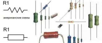
At first glance, we must estimate what maximum power the resistor can dissipate. From top to bottom, below in the photo, resistors by power: 2 Watt, 1 Watt, 0.5 Watt, 0.25 Watt, 0.125 Watt. On resistors with a power of 1 and 2 Watts they write MLT-1 and MLT-2, respectively.
MLT is a type of the most common Soviet resistors, from the abbreviated names M metal-film, varnished , heat -resistant. For other resistors, the power can be estimated based on their dimensions. The larger the resistor, the more power it can dissipate into the surrounding space.
Units of measurement in MLTs - Ohms - are designated as R or E. Kilo-ohms - with the letter “K”, Mega-ohms with the letter “M”. Everything is simple here. For example, 33E (33 Ohms); 33R (33 Ohm); 47K (47 kOhm); 510K (510 kOhm); 1.0M (1 MOhm). There is also a trick that letters can precede numbers, for example, K47 means that the resistance is 470 Ohms, M56 - 560 Kilohms. And sometimes, in order not to bother with commas, they stupidly push a letter there, for example. 4K3 = 4.3 Kilohm, 1M2 – 1.2 Megaohm.
Let's look at our hero. Let's look immediately at the designation. 1K0 or in the words “one and zero”. This means that its resistance should be 1.0 Kilohm.
Let's see if this is really true?
Well, yes, everything agrees with a small error.
Color coding of resistors
To determine the resistance value of a color-coded resistor, you first need to rotate it so that its silver or gold stripes are on the right and a group of other strips are on the left. If you cannot find a silver or gold strip, then you need to rotate the resistor so that the group of strips is on the left side.
Which side to count the stripes on the resistor?
The resistance of the resistor is determined by the first color rings:
- For elements with three stripes, the first two colors are numbers, and the third color is the multiplier.
- For elements with four stripes, the first two colors are numbers, the third color is the multiplier, and the fourth color is the permissible deviation of the resistor resistance from its nominal value.
- For elements with five stripes, the first three colors are numbers, the fourth color is the multiplier, and the fifth color is the permissible deviation of the resistor resistance from its nominal value.
- For elements with six stripes, the first three colors are numbers, the fourth color is the multiplier, the fifth color is the permissible deviation of the resistor resistance from its nominal value, and the sixth is the temperature coefficient.
The color markings on resistors are read from left to right. In this case, you need to correctly determine the left side. As a rule, the first stripe is applied closer to one of the resistor terminals. If the element is small in size and it is impossible to maintain the required proportions for marking delimitation, then the counting is based on the color stripe, which is the widest in comparison with the others.
Additionally, it can be noted that silver and gold colors are never used to indicate the first stripes on resistors. And, as can be seen from the calculation tables, digital values are not specified for these colors.
What is it for?
Low power resistors are very small in size, their power is about 0.125 W.
The diametric size of this version is about a millimeter, and the length is several millimeters. Reading the parameters, which often have several numbers, is quite difficult, as is plotting them. When indicating the denomination, if the dimensions allow, a letter is often used to determine the fractional value of the value.
An example is 4K7, which means 4.7 kOhm. However, this method is also not applicable in some cases.
The color scheme of the marking has the following features:
- Easy to read.
- Easier to apply.
- Can convey all the necessary information about denominations.
- Over time, information is not erased.
At the same time, we can note the main difference in this marking:
- At 20% accuracy , a marking containing 3 stripes is used.
- If the accuracy is 10% or 5% , then 4 stripes are applied.
- More precise versions have 5 or 6 stripes.
To summarize, we can say that applying colors allows you to find out the accuracy and nominal values of the resistor, for which you need to use special tables or online services.
Color coding of resistors with five and six stripes online calculation
Resistor calculator with five color stripes:
To determine the resistance of six-band resistors, you need to use a five-band element calculator and take into account the sixth color band, which represents the temperature coefficient of resistance. A detailed table of temperature coefficient of resistance (TCR) values and their relationship to a specific color is given in the following table:
| Color | TKS (ppm/ºC) |
| Brown | 100 |
| Red | 50 |
| Yellow | 25 |
| Orange | 15 |
| Blue | 10 |
| Violet | 5 |
| White | 1 |
Color coding of resistors
The first stripes of the resistors indicate numbers. Each number is assigned a specific color:
| Color | Meaning |
| Black | |
| Brown | 1 |
| Red | 2 |
| Orange | 3 |
| Yellow | 4 |
| Green | 5 |
| Blue | 6 |
| Violet | 7 |
| Grey | 8 |
| White | 9 |
Color coding of resistors
One of the main elements of constructing electronic circuits, despite the development of microprocessor technologies, is still the old proven resistors.
Resistance or resistors have largely undergone a number of changes over the past decades, including a significant reduction in overall dimensions - the current generation is half the size of devices produced 30-40 years ago, but at the same time, the need for them when creating electronics is not became smaller.
There were several reasons for the introduction of color marking of electronic elements:
- Due to the reduction in size, it was necessary to abandon the alphanumeric marking of devices.
- A color coding system allows you to encode much more information about an element than an alphanumeric designation system.
- The widespread introduction of robotics in assembly lines of electronic components required a change in approaches to marking component parts.
- In connection with the development of the production of radio components in the countries of East Asia, based on advanced technologies, the production of domestic components was significantly pushed back, which is why manufacturers had to switch to Western labeling standards.
In addition, a significant number of radio elements today are mounted on boards, the repair of which is impractical due to the high cost of the repair itself, because it is much cheaper to buy a new radio than to repair it, in view of this, many companies have practically abandoned service centers and, as a result, do not require a significant number of spare parts of different denominations .
Classification by manufacture
In addition to the typology of elements according to appearance and installation location, there is a classification according to production criteria.
Input resistance components are made:
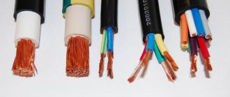
- wired _ The resistive component is a wire wound around a core. In order to reduce parasitic inductance, a bifilar winding type is used. The wire is selected from materials that have a low resistive temperature coefficient, including those with low resistivity;
- metal film . The main resistance element is a metal film;
- composite . The composition of such elements includes alloys.
Attention!
For the manufacture of SMD resistors, metal film is used. Accordingly, the division is into thin and thick film.
Elements are also divided into constants and variables. From the name you can guess that the load of the first remains unchanged throughout the entire period of operation. For variable components, the resistance indicator is changed using a special slider.
How to determine the resistance of a resistor by color?
Basically, today, it is almost impossible to find resistors older than 15-20 years, although some old rare “Records” and “Electrons” are still pleasing to the eye in some apartments.
Filled with Soviet electronics, old televisions and radios usually included standard resistors in brown or green colors with letter markings.
It is not difficult to understand the nominal value of an element by its alphanumeric encoding if you have a rare waste paper reference book at hand, especially since most of them were metal-film, varnished devices with the property of heat resistance - MLT.
In the Soviet Union, consumer electronics were a byproduct of defense industries, but were assembled from the same parts as military equipment. Such resistors differed from each other in size - the larger the element, the greater the resistance.
Today's component labeling is largely different in that there are several varieties - simple, standard color-coded cylindrical resistors and SMD elements.
Alphanumeric marking of resistors
On resistors from the times of the USSR, numbers and letters are printed, by which the characteristics of a given element can be determined. It costs two or three numbers and a Latin letter. The numbers are the denomination, the letter is the multiplier. With numbers, everything is more or less clear, but you need to remember which letter corresponds to which factor, or have a table at hand.
Table of decoding of letter designations in the marking of old-style resistors
If there is only a number without a letter, the numbers indicate resistance in Ohms, and the tolerance is 20%. That is, if it says simply 33, then you have a 33 Ohm resistor with a tolerance of 20%.
Examples of decoding alphanumeric encoding of resistors
Examples of deciphering codes on resistors:
- 3R9J - 3.9 ohm resistance with 5% tolerance. The letter R means that it is not necessary to multiply by one, that is, there is, in fact, no factor. Since the letter is between two numbers, it also shows the place of the comma. So we get a nominal value of 3.9 ohms. Tolerance is simple - in the corresponding column we find the required letter and look at the permissible deviations.
- 215RG - 215 Ohm resistance with 2% tolerance. The letter R comes after three digits, which means they must be multiplied by 1.
- 1K0J is a 1 kOhm resistor with a tolerance of 5%. The letter K denotes a multiplier of 10³. This means that the number that stands in front of it must be multiplied by 1000. It is much easier to put the letter “K” in front of the designation. The result is kOhm, which is read as “kilo Ohm”.
You can practice determining the denomination
As you probably already understood, without having a table, you can replace the Latin letters with the corresponding Russian ones. It's much easier this way. The only thing you need to remember is that the letter R or E is a multiplier of “1”. The situation is the same if there are no letters, but only numbers. The denomination is indicated in Ohms. If you learn this rule, marking resistors from the Soviet period will be easy to master.
Standard and non-standard color markings
In addition to the generally accepted, standard color marking of resistance designations, there are also non-standard types of coding. Most often, non-standard markings are found in the form of a combined color code and numbers in some large electronics manufacturers that have their own divisions for the development and production of electronic components.
Among such non-standard color codes and letter designations, the most common are Philips and Panasonic; these manufacturers mark radio components produced at domestic enterprises with markings different from the generally accepted ones, for which special reference books and computer programs are used.
Purpose and examples of calculating color markings of resistors
The main purpose of resistors is to convert current into voltage or perform the reverse process, limit the current, and absorb electrical energy. Used in almost all complex electrical circuits, so pay attention to the color coding.
- Standard color coding ↓
- What is it for? ↓
- Online calculators ↓
- Universal color chart ↓
- Examples ↓
- Summary table of resistor color markings ↓
- Features of marking wirewound resistors ↓
- Non-standard marking of imported resistors ↓
Due to their small size, resistors are rarely marked with a numerical or letter value. Most often, colors are applied, which determine all the basic qualities. In order to choose the right resistor, you should know the features of applying colored dots or lines.
Explanation and table
As already stated, the color marker rings are applied from left to right.
The first ring and the second colored ring following it indicate the standard resistance value in Ohms. The next, third ring indicates the multiplier by which the numerical value of the first two units of the designation must be multiplied, the fourth ring of the code indicates the value by which the declared denomination deviates as a percentage.
To accurately determine the resistance value of each individual component, you do not need to memorize the entire color code; it is enough to have a resistance determination table at hand:
| Sign color | Nominal resistance, Ohm | Tolerance, % | TKS [ppm/°C] | |||
| First digit | Second digit | Third digit | Factor | |||
| Silver | 10-2 | ±10 | ||||
| Golden | 10-1 | ±5 | ||||
| Black | 1 | |||||
| Brown | 1 | 1 | 1 | 10 | ±1 | 100 |
| Red | 2 | 2 | 2 | 102 | ±2 | 50 |
| Orange | 3 | 3 | 3 | 103 | 15 | |
| Yellow | 4 | 4 | 4 | 104 | 25 | |
| Green | 5 | 5 | 5 | 105 | 0,5 | |
| Blue | 6 | 6 | 6 | 106 | ±0,25 | 10 |
| Violet | 7 | 7 | 7 | 107 | ±0,1 | 5 |
| Grey | 8 | 8 | 8 | 108 | ±0,05 | |
| White | 9 | 9 | 9 | 109 | 1 | |
Series of preferred values for electronic components
At the beginning of the 20th century, resistors were used mainly in radio receivers and, together with other components, were called radio components. Now this name refers to all elements used in electronic circuits that have nothing to do with radio and therefore radio components began to be called electronic elements and components (this, as always, is a tracing paper from English). Although this is how to say it! The phone has at least five radio receivers (for communication with the base station, GPS/GLONASS, Wi-Fi, NFC, VHF receiver), but no one remembers this and does not consider the phone a radio receiving device. But we digress from the topic. Although it is possible to make a resistor with any resistance, it is more convenient to produce a limited number of components, especially since each resistor has a certain tolerance on the value. More precise resistors cost more than less precise resistors. Conventional logic shows that for standard values it is convenient to choose a logarithmic scale, with equal intervals between standard values, which are determined taking into account the permissible deviation from the nominal value. For example, for an accuracy of ±10%, it makes sense for a decade (the interval in which the resistance changes from 1 to 10, from 10 to 100, and so on) to take 12 values: 1.0; 1.2; 1.5; 1.8; 2.2; 2.7; 3.3; 3.9; 4.7; 5.6; 6.8; 8.2, then 10; 12; 15; 18; 22; 27; 33; 39; 47; 56; 68;82 and so on. These values are called denomination series. They are standardized in the form of series E3–E192
and are used not only for resistors, but also for capacitors, inductors and zener diodes. Each row (E3, E3, E6, E12, E24, E48, E96, and E192) divides the decade into 3, 6, 12, 24, 48, 96, and 192 standard values. Note that the E3 series is outdated and used extremely rarely.
Online calculator
Interface of the program “Resistor 2.2”
Modern technologies today greatly facilitate the work of both professionals and radio amateurs. In addition to accessible measuring equipment, today in Internet resources dedicated to radio engineering there are a huge number of online calculators for determining the resistance of resistors by marking.
Simple, and generally reliable programs allow you to accurately determine the rating of almost any radio component; more advanced and powerful engineering programs used in packages for design engineers allow you not only to find out the resistance value, but also to find an appropriate replacement and determine the option the performance of the circuit itself.
One of such programs is the Resistor 2.2 program; it is simple, convenient and does not require deep knowledge of computer technology. A simple interface and convenient working elements allow you to work both online and without it.