What is an AVR device
The ATS automatically turns on the backup power source in an emergency.
Maintaining the operating state of the power source is ensured using special engineering solutions. In the event of an emergency, the automation switches on the generator. The necessary actions are performed without careful control and intervention from the user.
The main functional components of a typical ATS system:
- control devices record changes in the electrical parameters of the power supply network;
- when a circuit break (SC) or deviation from the set threshold level is detected, the automation switches off the damaged section;
- The alarm device reports a violation of the operating mode;
- the contact group connects the standby power source.
Next, the necessary measures are taken to restore the standard system. The abbreviation (AVR) stands for “Automatic Reserve Entry”. In addition to the standby generator, switching to a working network or battery bank is used.
Description of the device
Automatic transfer of reserve is a system that is needed to provide power supply loads with a reserve charge. It is carried out in two versions. It can be one-sided or two-sided. In the first there is a division into a working and a reserve section, but in the second there is no such thing. In the first case, you can switch to normal mode or emergency mode; in the second case, these modes are not necessary.
We advise you to study the rules and methods of bedroom lighting
Safe operation of electrical equipment as one of the purposes of the device
The main purpose of the module is to make the power supply system more reliable. This device quickly connects loads to the backup input type when power outages occur. To ensure automatic switching, the system monitors voltage and current at all times. This is its purpose.
Explanation of the abbreviation AVR
The abbreviation is deciphered very simply. ATS is an automatic transfer of reserve. Sometimes switching is used instead of the word input, but this is incorrect, because by input is meant generator start-up as a backup source.
How does the abbreviation stand for?
Classification
Depending on the design of the AVR unit, the equipment is classified according to the number of sections, type of network, voltage class, power and response time.
Note! ATS is often available with one, two and three outputs to ensure high network reliability. Also available in single-phase, two-phase and three-phase
According to the voltage class, it handles up to 1000 volts.
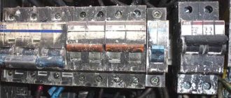
AVR cabinet for three inputs
Primary requirements
When purchasing and installing on a network, users are required to have the ATS:
- ensured the supply of energy in the event of an unforeseen interruption in line operation;
- restored electrical power as quickly as possible;
- necessarily acted once, that is, there should not be several modes of operation at once;
- turned on the main power before the backup electrical power was supplied.
In addition, it must monitor the health of the equipment control circuit.
Fast restoration of electrical power is the main requirement for the system
Purpose of AVR
The functionality of the system is based on the principles of ensuring uninterrupted operation of the power supply. Automation of basic processes involves eliminating the actions of maintenance and operational personnel. Professional requirements for equipment are set out in the rules of the PUE. In particular, to connect consumers of the 1st category, an ATS circuit with 2 inputs with a sectioner on automatic machines is used.
Duplication of switchgear and other critical elements ensures a high level of reliability. Such units are designed for autonomous operation. During the creation of design documentation, mutual influence is excluded to prevent erroneous actions of the automatic transfer switch.
The need to use such systems is illustrated by the example of a well-equipped private country house. As a rule, a local heating system is installed in such facilities. The control of a modern gas boiler is provided by electronics. Pumps are used to force coolant circulation through the circuits. Disabling these components in severe frost provokes destruction of pipes and radiators.
Repair and restoration work is much more expensive compared to autostarting a special generator. The presence of a standby power source is useful in case of accidents in power supply networks. If the voltage connection is fast enough, users will not experience any discomfort.
ATS with input priority selection: how does it work?
The abbreviation AVR stands for quite simply - automatic reserve entry. Why is this necessary? At least in situations where the main power source does not cope with its task. This can happen for many reasons, but being left without electricity for a long time (and sometimes for a short period) is unpleasant and fraught with consequences. Especially when it comes to enterprises where it is necessary to constantly maintain a certain temperature. A power outage will lead to significant financial losses. And in domestic conditions, the AVR will serve well.
Monoblock AVR 25-800A 79 products from 21,276 ₽
AVR cabinets for 2 inputs 25-3200A 18 products from 29,900 ₽
AVR cabinets for 3 inputs 63-630A 7 products from 79,900 ₽
ATS for generator (DGU) with auto start 6 products from 39,900 ₽
Operating modes.
An automatic switch is a panel that needs to be installed and connected. And like any other device, it has two control systems:
— Manual; — Automatic.
Let's take a closer look at each of them and immediately note that slot machines always have the option of choosing a system. Switching is carried out using a lever located on the front side of the shield.
Manual mode.
For easy and independent operation of the ATS, there are connection diagrams that allow you to remotely control the device. Schemes will not be needed manually. Control is carried out using special buttons (adjust inputs and sections):
1. Input-1 (SB1 and SB2) 2. Input-2 (SB3-SB4) 3. Intersectional automatic machine (SB5-SB6).
The principle of operation of automatic reserve in this mode is easier to consider using the example of the first input. To start its operation, you must press the correspondingly marked button on the case (SB1). Next, the mechanism begins to operate: phase L1 is turned on from the control circuit breaker, which activates the normally open wire of the contactor K1.1. Then the normally closed wire SP1 (switch) comes in. It was previously set to manual mode. Next, the machine’s connector (electromagnetic drive coil) is activated, which receives impulses from two groups of contacts (n.o. and n.c.). Phase zero N operates and the device starts.
To turn it off, press SB2. The principle of operation of the circuit is similar: phase L1 - normally open wire of the contactor - normally closed contact of the switch - wires of the shutdown button are turned on - the connector of the machine and the drive coil are active - then the connector of the machine 4 - neutral and the ATS is turned off.
The second and intersection inputs are controlled according to a similar principle. Manual mode is convenient in emergency situations, if for some reason the automation fails to cope with the task. It is difficult and impractical to constantly act according to such a scheme.
Auto mode.
In this case, the control buttons are completely blocked. The MS machine is turned on if:
1. The main power supply has turned off and the electricity is completely lost; 2. Phase failure (voltage is supplied asymmetrically); 3. The supplied voltage is less than the relay setting; 4. The applied voltage is significantly higher than the relay setting; 5. The phases alternate in the wrong order (correctness can be checked using special devices); 6. The phase is interrupted.
We control it using a relay and phase sequence. The first has light bulbs on the front side that glow green when in working condition. The output wire is closed. It is through it that the coil and inputs are “powered”. If the voltage disappears at one of the inputs, the lights turn red and the device breaks the contact. Then the intersection device is turned on. As soon as the voltage supply is restored at the disconnected input, the output contact closes again. The relay coil receives voltage and turns on, and the lights turn green again.
To put it very simply: when the power is lost at one of the inputs, the intersectional machine is turned on, which allows the devices connected to the network to operate in normal mode.
AVR schemes.
With input priority.
We have already found out that there can be two inputs. One of them can be made the main one and usually this is the first input. If an emergency occurs, voltage surges, phase failure, and so on, the voltage on it may disappear. In this case, the machine switches electrical impulses to the second input and makes it the main one. When the power supply to input-1 is restored, the ATS returns to its original settings. You can also make the second input a priority (for some types of network this is important), the operation scheme will be the same.
Manual priority selection.
The previous principle of operation is based on automation, but manual selection is a more complex scheme. In this case, the priority is set by the user independently using a switch.
Sectional priority.
When voltage is supplied to both inputs without interruption, they receive power through the reserve circuit breakers QF1 and QF2. Let's say there is a malfunction at the first input, then QF1 turns off and QF3 (sectional switch) turns on. It supplies load to the first input from the second input. Thus, the supply of electrical energy is restored in a matter of seconds. As soon as the problem is resolved, the sectional QF3 is turned off, and the machine operates as usual.
No priority.
Also a very simple circuit. There are no main power sources provided. For example, the voltage is constant at input-1. If it stops working, the load switches to input-2. And when restored, it remains at the same input.
The principle of operation of each of the circuits is very similar, and the choice depends on the characteristics of the room, the ATS itself and the characteristics of the equipment connected to the sockets.
AVR systems 25-3200A 126 products from 19,200 ₽
AVR 25-630A on contactors 5 products from 24,100 ₽
AVR 63-630A with sectional switch 8 products from 79,900 ₽
Single-phase automatic transfer switches 20-63A on contactors 3 products from 19,200 ₽
Principle of operation
To study working algorithms, you can use an example of an assembly based on a simple element base.
- Constant monitoring of the electrical parameters of the main line is provided by the contactor.
- Alternating current through the switch through a closed circuit enters the local network to consumers.
- If the voltage is lost, the induction coil will not be able to hold the rod.
- The spring will move the reserve input contact group through the actuator to close.
- At the same time, the main machine is turned off.
- When voltage appears in the operating line, the steps are performed in the reverse order.
Light bulbs in the corresponding circuits signal the start of certain modes.
Operating principle of automatic reserve entry
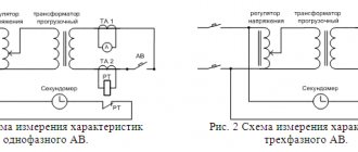
Regardless of the version of the ATS, the system’s operation is based on monitoring network parameters. For this purpose, both voltage control relays and microprocessor control units can be used, but the operating principle remains unchanged. Let's consider it using the example of the simplest ATS circuit for uninterrupted power supply to a single-phase consumer.
Rice. 4. Simple circuit of a single-phase ATS
Designations:
- N – Zero.
- A – Working line.
- B – Backup power supply.
- L – Lamp acting as a voltage indicator.
- K1 – Relay coil.
- K1.1 – Contact group.
In normal operation, voltage is supplied to the indicator lamp and relay coil K1. As a result, the normally closed and normally open contacts change their position and the load is supplied with power from line A (main). As soon as the voltage at input A disappears, the light goes out, the relay coil stops being saturated, and the contact position returns to its original state (as shown in the figure). These actions lead to the inclusion of a load on line B.
As soon as the voltage is restored at the main input, relay K1 re-switches to source A. Based on the principle of operation, this circuit can be classified as a one-way design with a return function.
The diagram presented in Figure 4 is greatly simplified; for a better understanding of the processes occurring in it, we do not recommend using it as a basis for the ATS controller.
System requirements
The functionality of the presented circuit is limited. If a fault in the main line is accompanied by a short circuit, restarting will damage the load. The reactive characteristics of electric motors have a certain influence. When connecting a machine or a powerful fan, a voltage drop can cause a false operation of the protection system.
Separately, you should consider the connection speed of the backup source. For significant time intervals, local protection circuits are triggered in some connected devices. Such situations are accompanied by malfunctions. They provoke breakdowns and accelerated wear of drives.
To eliminate the shortcomings, logical control circuits are used, created on the basis of electronic units with specialized software. Some components are equipped with mechanical locking units. Such elements remain operational even when the main and emergency power are completely disconnected.
Basic requirements for modern ATS:
- reliability of connecting a backup power source (PS) during peak loads and significant changes in network operating parameters;
- sufficient speed to prevent damage to electricity consumers;
- adjustable setting of threshold levels for turning on the protection system;
- blocking connection to a circuit with a short circuit and parallel connection of two inputs;
- single operation;
- automated check of the functional state of the backup IP.
Smooth switching is ensured by adding transformers to the circuit.
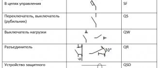
Requirements for ATS and their types
ATS systems are subject to a number of technical requirements regarding the efficiency of the switchings they make. They are that the backup scheme must:
- Instantly switch the serviced object to the auxiliary power source IP (switching delay should not exceed 1-2 seconds);
- Guarantee the one-time operation of the ATS system and high quality of power supply during the shutdown of the main supply line;
- Have a large temporary operating resource, sufficient to have time to put into operation the emergency shutdown main network;
- Do not respond to short circuits and random “sags” of the supply voltage in the serviced load;
- Ensure the possibility of joint operation of both power sources (a diagram of such connection is given below).
Joint operation from 2 inputs
The indicated figure shows the following graphic symbols:
- Input 1 – main power supplied through transformer T1;
- EA – backup power unit, represented by a generator under the designation G;
- Q1, Q2 – executive units (contactors) of the automatic transfer switch.
If the system's power is insufficient, only the most important consumers are connected to it (an operating room in a hospital, for example, or a refrigerated warehouse for medicines).
The working connection of the reserve input is carried out in the prescribed manner, determined by the specific operating conditions of the entire system as a whole (they are usually specified in the terms of reference for a standard ATS project). Problem areas in the operation of these systems include a significant level of impulse noise that occurs when the relay switch is activated during switching.
The formation of sharp surges in voltage and current is explained by transient processes that cannot be avoided in the presence of nonlinear elements in switched circuits (the inductance of relay coils, in particular).
We also draw your attention to the fact that automatic reserve entry can have several versions that differ in the principle of their operation. In accordance with this division, it can be:
- One-sided, that is, consisting of a regular and additional individual entrepreneur; in this case, the backup circuit is connected only when the main power is lost;
- Double-sided. This means that any of the supply systems can serve as both a working and a backup source at the same time;
- The so-called “recoverable” ATS (when, from the moment the main power supply appears, the previous circuit is put back into operation, and the backup power supply is removed).
And finally, an operating mode is possible in which the system returns to its normal state not automatically, but through manual switching.
Automation selection
PromEnergo AVR unit
Industrial equipment and professional equipment are equipped with automatic equipment as standard. At a minimum, they offer a box with a set of contactors to reproduce the protective algorithm. An emergency button is placed in the accessibility zone. If necessary, the unit can be turned off by hand in one quick movement.
A specialized AVR shield can be purchased assembled or you can create a functional analogue yourself. When choosing a finished product, you should pay attention to the reputation of the manufacturer. A preliminary study of customer reviews and the opinions of experienced experts will be useful.
In the lower price range there are products of dubious origin. If a single-phase ATS costs up to 1500-2000 rubles, you can hardly count on a long service life and high reliability. Counterfeits are characterized by poor assembly and low quality contact groups. Quite often, such models use low-power electronic switches that are not adapted to voltage surges and loads with pronounced inductive characteristics.
From 4,000 to 8,000 rub. you can find high-quality AVRs from little-known brands. Reliable equipment sets use electromechanical functional components.
In the range from 20,000 rub. and above are products from responsible manufacturers. These products are provided with official warranties. Performance and other important parameters are monitored in each individual product batch.
Automation without controller
The decoding of the designation emphasizes the main feature of equipment in this category. The “automatic” method of connecting a modern level of reserve implies not only the absence of user intervention. The electronic controller provides quick check of the state of the supply and backup networks. It blocks erroneous operations and prevents the occurrence of potentially dangerous situations. When choosing an ATS, you should check whether this useful component is included in the kit.
ATS in 0.4 kV networks
To switch power circuits in networks with relatively low voltage (0.4 kV), serial contactors with a magnetic drive are used. Starters are also used complete with AB. Circuit components are selected taking into account current loads (power consumption).
In typical ATS switchboards with 2 inputs, electricity metering devices, surge protection devices, and relays with a delay function are installed to create an additional time interval before connecting the load.
Automation without controller
there is a serious drawback
Automation in this version cannot turn off the network at low and high voltage, as well as control the parameters of the power plant, record important events and errors, on the basis of which diagnostics will be carried out in the future.
We advise you to study Conductors and Dielectrics
In practice, the operation of the ATS unit will be reduced to the following: one or two LEDs will act as informing elements, and in accordance with the instructions, one blink will correspond to one situation, double blink to another situation, and if there is a pause between the blinks, to a third situation. If you entrust the installation of this device to a specialist, then do not be surprised if he refuses to work with this travesty or demands that you pay more for the work.
Classification of ATS and implementation options
The following schemes for organizing working algorithms are used:
- One-way means connecting a backup input if necessary. For example, for temporary power supply from a battery.
- In the double-sided design, both sections are equivalent. This solution is used if switching to a backup network with similar parameters is possible.
The logic of the restoration process is separately determined. Use:
- subsequent automated connection to the main line;
- switching to backup power with manual mode change.
Features of working with household generators
The popularity of this solution is due to the ease of choosing equipment with the required power. In the corresponding market segment, they offer generators driven by gasoline (diesel, gas) engines for connection to single- and three-phase networks. They are designed for long-term continuous operation without careful supervision. Autonomy actually depends only on the fuel supply.
To start the power unit, the sectional automation cabinet is equipped with a specialized control unit. It supplies power to the starter according to the established algorithm. In particular, you can configure the program to preheat the diesel engine in winter conditions.
Battery-powered ATS
These backup power supplies supply direct current to the line. An inverter is used to convert it to a sine wave of a certain amplitude (220 or 380 V). You should understand the limited autonomy of this option. However, parallel connection of several batteries can provide the required time interval. A promising direction is lithium-ion energy storage devices. They are superior to lead-acid analogues in their main technical characteristics. The high price limits widespread use. However, as demand increases and production expands, manufacturers are beginning to offer quality products at reasonable prices.
Connecting a battery is simpler compared to a generator. In this version, the ATS can be assembled according to a standard scheme without a special engine start control unit.
Application of Logic Controller
Such blocks are used to fine-tune the algorithm of work operations. Special regulators set the permissible percentage of voltage deviation from the nominal value, time intervals, and other parameters. The control signal circuits are connected to switching devices.
Organization of automatic transfer switches in high-voltage circuits
To simplify monitoring of network operating parameters, a step-down transformer is used. A certain number of turns reduces the voltage from 1000 to 100 V. If a phase control relay is added to the control circuit, the reserve is connected when at least one line breaks.
Connection diagrams
The optimal option is chosen taking into account:
- operating parameters of the power supply network;
- type of loads;
- special requirements for the speed of reserve input and other parameters.
For single-phase networks when connecting a private home or a small commercial facility, you can use the simplest option using modular contactors with a two-pole AC. The ATS circuit with a phase control relay for two inputs is used when connecting powerful loads. In the appropriate version, in addition to the voltage level, sinusoid distortion and phasing correctness are monitored. If you plan to work with several sources (more than two), create a system with the required number of inputs.
Scheme options for implementing ATS with descriptions
Here are a few working examples that can be successfully used when creating an automatic launch panel. Let's start with simple circuits for an uninterrupted power supply system for a residential building.
Simple
Below is a variant of the ATS circuit that switches the supply of electricity to the house from the main line to the generator. Unlike the example above, there is short circuit protection, as well as electrical and mechanical interlocking, which prevents simultaneous operation of two inputs.
AVR diagram for home
Designations:
- AB1 and AB2 are two-pole circuit breakers on the main and backup inputs.
- K1 and K2 are contactor coils.
- K3 – contactor acting as a voltage relay.
- K1.1, K2.1 and K3.1 are normally closed contacts of the contactors.
- K1.2, K2.2, K3.2 and K2.3 are normally open contacts.