Why do we need color coding for wires and cables?
Installation and maintenance work in electrical installations is associated not only with ensuring reliability, but also safety. Complete error elimination is required. For these purposes, a system of color designations for core insulation has been developed, which determines what color the wires are phase, neutral and ground.
According to the PUE, the following colors of current-carrying conductors are allowed:
- red;
- brown;
- black;
- gray;
- white;
- pink;
- orange;
- turquoise;
- purple.
The above list contains many options for wire colors, but there are not several colors that are used only to indicate neutral and protective wires:
- blue color and its shades - working neutral wire (neutral - N);
- yellow with a green stripe - protective earth (PE);
- yellow-green insulation with blue marks at the ends of the conductors - combined (PEN) conductor.
It is allowed to use conductors with green insulation with a yellow stripe for grounding, and for combined conductors blue insulation with yellow-green marks at the ends.
The color must be the same in each circuit within one device. Branch circuits must be made with identically colored conductors. The use of insulation without differences in shades indicates a high standard of installation and greatly facilitates further maintenance and repair of equipment.
What are the colors of phase, neutral and ground wires in apartments or private houses?
Play a key role for maintenance and repair. It greatly simplifies the work for the craftsmen and speeds up troubleshooting.
- Colors in electrical wiring: importance and practicality
- How are wires painted on electrical wiring?
- Is the color designation always the same for a 220 V network?
- What colors are in electrical wiring?
- Ground wire color
- What is the phase designated by?
- Neutral wire in a single-phase network
- How to check the correctness of the markings in the apartment?
- Designation of colors on electrical diagrams
- Useful video
The human eye does not see the electric field, and therefore is not able to detect live wires. Touching them is extremely dangerous and can be fatal. To protect people and reduce risks to the system, standards were adopted (GOST R 50462-92).
Oil-impregnated paper and plastic insulation are the most common in Russia. The first is used in an aggressive environment because of its ability to regenerate, that is, restore its previous properties. Today, PVC insulation is gaining great popularity.
Neutral color
What color the neutral wire is is specified by GOST , so when looking at the installation of a power plant, the question should not arise whether the blue wire is a phase or a zero, since the blue color and its shades (blue) are accepted to indicate neutral (working grounding).
Other colors of neutral cores are not permitted.
The only acceptable use of blue and cyan insulation is to indicate the negative pole or midpoint in DC circuits. This color cannot be used anywhere else.
Color of conductors in the cable according to PUE 7, GOST R 50462 and GOST 31996
clause 1.1.29. For color and digital designation of individual insulated or non-insulated conductors, colors and numbers must be used in accordance with GOST R 50462 “Identification of conductors by colors or digital designations”.
Protective grounding conductors in all electrical installations, as well as neutral protective conductors in electrical installations with voltages up to 1 kV with a solidly grounded neutral, incl. tires must have the letter designation PE and a color designation with alternating longitudinal or transverse stripes and the same width (for tires from 15 to 100 mm) in yellow and green .
Zero working (neutral) conductors are designated by the letter N and the color blue . Combined neutral protective and neutral working conductors must have the letter designation PEN and color designation: blue along the entire length and yellow-green stripes at the ends
According to GOST R 50462
(GOST R 50462-2009 (IEC 60446:2007) Basic principles and safety principles for the human-machine interface, implementation and identification. Identification of conductors by means of colors and alphanumeric designations)
In accordance with Table A.1 of Appendix A. (read the original table)
AC electrical circuit
- Single-phase phase conductor - Brown
- Phase conductor 1 of three-phase circuit - Brown
- Phase conductor 2 three-phase circuit - Black
- Phase conductor 3 three-phase circuit - Gray
- Grounded phase conductor of a single-phase circuit - Blue
- Grounded phase conductors of a three-phase circuit - Blue
- Neutral conductor - Blue
DC electrical circuit
- Positive Terminal - Brown
- Negative Terminal - Gray
- Grounded Positive Pole Conductor - Blue
- Grounded negative pole conductor - Blue
- Middle conductor - Blue
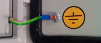
Ground wire color coding
The rules indicate what color the ground wire in electrical installations is. This is a yellow-green wire, the color of which stands out well against the background of the other wires. It is acceptable to use a wire with yellow insulation and a green stripe on it, or it can be green insulation with a yellow stripe. It is not allowed to use any other color of the ground wire, just as it is not allowed to use green-yellow conductors for installing circuits on which voltage is present or may be applied.
The listed labeling rules are observed in the countries of the post-Soviet space and in the countries of the European Union. Other states mark the cores in a different way, which can be seen on imported equipment.
Basic colors for marking abroad:
- neutral - white, gray or black;
- protective grounding - yellow or green.
Standards in a number of countries allow the use of bare metal without insulation as protective grounding.
Grounding wires are switched on prefabricated non-insulated terminals and connect to each other all metal parts of the structure that do not have reliable electrical contact with each other.
Rules for marking live parts according to the PUE
To ensure clarity, simplicity and ease of recognition of individual parts of the electrical network, in accordance with clause 1.1.30 of the PUE, all electrical installations must have an alphanumeric and color designation. Moreover, the presence of one of these designations does not eliminate the need for the other.
And the only relaxation is the possibility of applying a designation not along the entire length of the conductor, but only at the connection points, as shown in the video.
Wire color coding
Marking wires by color is the most visual and allows you to quickly determine the purpose of any wire. This marking can be done by selecting wires with the appropriate core insulation color, by applying paint to the busbars, or by painting or applying special colored tape at the core junctions.
Moreover, the paint on the tires may not be applied along the entire length, but only at the connection points or at the ends of the tires.
- If we talk about the color designation of wires and cables, then we should start with the phase conductors. According to clause 1.1.30 of the PUE in a three-phase network, phase conductors must be marked in yellow, green and red. This is how phases A, B and C are designated respectively.
- The instructions for a single-phase electrical network suggest the designation of the phase wire in accordance with the color of which it is a continuation. That is, if a phase conductor is connected to phase “B” of a three-phase network, then it should be green.
Note! In a single-phase network in an apartment or house, you often do not know which phase your phase wire is connected to. In order to comply with GOST, you do not have to find out this at all. It is enough to designate the phase conductor with any of the proposed colors. After all, for a single-phase lighting network, it does not matter at all which phase your conductor is connected to. The only exception is the lighting network, which uses two different phase conductors.
- As for the neutral conductors, they should be blue in color. Moreover, the color of the neutral core does not depend on the three-phase, two-phase or single-phase network in front of you. It is always indicated in blue.
- Wire markings with a yellow-green stripe indicate a protective conductor. It is connected to the housing of electrical appliances and provides safety from electric shock if the insulation of electrical equipment is damaged.
Colors for 220V and 380V networks
Installation of single- and three-phase electrical networks is facilitated if the wiring is made with multi-color wire. Previously, a flat two-core white wire was used for single-phase residential wiring. During installation and repair, to eliminate errors, it was necessary to ring each core individually.
The production of cable products with colored cores in different colors reduces the labor intensity of the work. To indicate phase and zero in single-phase wiring, it is customary to use the following colors:
- red, brown or black - phase wire;
- other colors (preferably blue) - neutral wire.
The phase markings in a three-phase network are slightly different:
- red (brown) - 1st phase;
- black - 2 phase;
- gray (white) - 3 phase;
- blue (blue) - working zero (neutral)
- yellow-green - grounding.
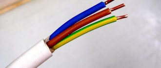
Domestic cable products comply with the standard for core coloring, so a multiphase cable contains differently colored cores, where the phase is white, red and black , the neutral is blue , and the ground is yellow-green conductors.
When servicing networks installed according to modern standards, it is possible to accurately determine the purpose of the wires in the junction boxes. If there is a bundle of multi-colored wires, the brown one will definitely be phase. The neutral wire in distribution boxes has no branches or breaks. The exception is branches to multi-pole switching devices with complete circuit breaking.
Color of wires in a three-phase network (380 V)
According to the PUE clause 1.1.30 and GOST, which was in force until 01/01/20011, phase wires were designated yellow (L1,A), green (L2,B) and red (L2,C).
Now these phases are gray, brown and black. When laying busbars, it is enough to paint the connections to the equipment and connections to the cables with the appropriate color.
Friends, now I would like to justify the above information with the rules and GOSTs in which all this is stated.
Rules and GOST for marking wires by color
According to the PUE clause 1.1.30, to simplify repair and installation work, as well as to prevent erroneous connection of wires, conductive parts of the electrical network must have alphanumeric and color markings, and the presence of one type of markings does not negate the need to use another.
It also states that marking is carried out in accordance with GOST R 50462-92. Clause 3.1.1 of this document indicates which colors of wire insulation and tire painting can be used for marking. The required color is indicated on the electrical diagrams by a letter code. The ratio of colors and letters is determined by GOST 28763-90
A specific indication of what color the phase is is noted in the PUE clause 1.1.29:
- the neutral conductor is indicated by blue color and the letter “N”;
- the grounding conductor is indicated by yellow-green longitudinal stripes and the letters “PE”;
- the wire that combines the functions of grounding and neutral is blue, the ends must have yellow-green tags, the letter designation of such a conductor is “PEN”.
All other colors are allowed to indicate phase conductors. Three-core cables usually use brown, five-core cables usually use white and other colors.
Changes to GOST
In particular, clause 5.2.3 indicates what color the phase is indicated by. The recommended colors for such conductors are grey, brown and black. This is how the new rules differ from the standard colors that have been in force for many years - yellow, green and red (familiar in the housing and communal services union).
Information! New color coding is used to avoid confusion - the grounding conductor is yellow-green.
According to GOST R 50462-2009 clause 5.2.1, it is prohibited to use yellow and green conductors separately if there is a risk of erroneous identification.
Despite the introduction of the new GOST, there is no need to redo the existing electrical wiring. New rules are mandatory only when laying new networks or replacing old wiring.
If it is not possible to use conductors with insulation of the required color, the ends of the wires must be marked in one of the following ways:
- put on pieces of PVC or heat-shrinkable tubing of the required color;
- wrap insulating tape;
- Press NSHVI lugs onto the ends of the wires.
What to do if the color markings do not match?
When performing repair work, it becomes necessary to determine what color the phase is in the existing electrical wiring. To do this, you need to take into account several rules:
- 1. The yellow-green conductor is ALWAYS the grounding PE
- 2. Blue (cyan) should always be neutral N (zero).
- 3. In single-phase wiring, the phase wire must have a brown sheath. Instead of brown, the phase can be indicated by other priority colors (gray, white, red, etc.). It should not be blue or yellow-green.
- 4. If there are no yellow-green wires in the cable, but there are simply green ones, the green conductor is connected to ground.
When connecting a two-key switch, three cable cores are used and you can often see a picture where in the distribution box a phase is supplied to the common terminal of the switch through the yellow-green wire. This is not recommended! The “common phase” in such cases should be brown or another priority color (gray, white, red, etc.).
If it turns out that all the wires are the same color or the color of the phase-zero-ground designation is different from those indicated above, then you can use colored electrical tape or heat-shrinkable tubing for marking.
Important! The presence of color markings and tags on the ends of the wires does not eliminate the need to turn off the circuit breaker and check the absence of voltage during repairs
Compliance with all the rules for color marking of wires will simplify repair work and help avoid mistakes when installing electrical wiring.
https://domashnysvet.ru/elektroprovodka/markirovka-provodov-po-cvetamhttps://elektrika.expert/provodka/cvet-provodov-v-jelektroprovodke.htmlhttps://stroychik.ru/elektrika/cvetovaya-markirovka-provodovhttps: //electricvdome.ru/montaj-electroprivodki/kakogo-cveta-faza.html
Coloring in DC networks
For DC networks, it is customary to mark conductors connected to the positive pole in red, and to the negative pole in black or blue. In bipolar circuits, blue insulation is used to mark the midpoint (zero) of the power supply.
There are no standards for color codes on multi-voltage circuits. What color are the plus and minus wires, what voltage is in them - this can only be determined by the decoding of the device manufacturer, which is often given in the documentation or on one of the walls of the structure.
Example: computer power supply or car wiring.
Automotive wiring is characterized by the fact that in it the circuits with positive voltage of the on-board network are red or its shades (pink, orange), and those connected to ground are black. The remaining wires have a specific color, which is determined by the car manufacturer.
Colors of wires and buses in DC circuits
DC circuits typically use only two buses, namely plus and minus. But sometimes DC circuits have a middle conductor. According to the PUE, buses and wires are subject to the following markings in DC circuits: positive bus (+) - red, negative (-) - blue, zero operating M (if available) - blue.