Types of multimeters
To begin with, you should know that multimeters can be digital and analog (pointer, also known among electricians as “tseshka”). The latter have been known to electricians for a long time, but using them without special knowledge and practice is quite difficult.
- you need to be able to understand the scales of the device, of which there are several on the dial multimeter;
- The device should be held in a position where the needle on it does not “walk” along the scale.
That is why, if possible, it is better to use a digital multimeter. We will also consider examples using a digital device, since it is quite difficult to learn to work with analog multimeters on your own.
There are quite a few types of digital multimeters, but the principle of their operation is similar to each other - the difference is only in the number of functions of the device. Accordingly, the price depends on the functionality of the multimeter, so before purchasing it, decide what you need it for.
The multimeter consists of:
- the device itself;
- two probes (black and red);
- power source (9 V Krona battery).
So, what are the features of using this measuring device and how to check amperes with a multimeter?
power unit
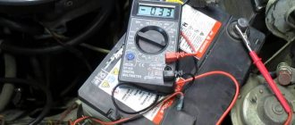
Today, a car enthusiast should be armed with all the benefits of technical equipment. These include a garage power supply, which is a powerful, reliable, completely universal device and, most importantly, absolutely safe. It is quite possible to assemble it with your own hands, having at your disposal a transformer and other necessary parts, or purchase it in a store. In the first case, it is allowed not to install a device for measuring voltage; simply the indicator of this value on the block will have to be measured using a multimeter. Working with such a device is quite convenient. It allows you to keep the battery running, start the engine for periodic recharging, and open the garage door for ventilation. With the help of the block, it is possible to check almost all the car’s devices for functionality, and customize car enthusiast designs. The power supply will recharge the battery without any problems, but it should not be used as a starting element - it will definitely burn out.
A few words about current strength, and why it needs to be measured
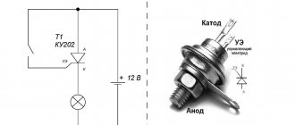
First, let's remember what it is - the strength of electric current.
This indicator (I) is measured in amperes and is one of the main physical quantities that determine the parameters of a particular electrical circuit. The other two are voltage (U, measured in volts) and load resistance (R, measured in ohms).
As taught in a school physics course, electric current is the directed movement of charged particles along a conductor. Considered with great simplification, it is caused by electromotive force arising from the potential difference (voltage) at the poles (terminals, contacts) of the connected power source.
The amount of current in the circuit is affected by two other parameters. Voltage is related by direct proportionality - for example, its increase causes an increase in current. Resistance is the opposite, that is, as it increases at the same voltage, the current strength decreases.
A funny picture that clearly demonstrates the relationship between the basic quantities of an electrical circuit: “Volt strives to “push” Ampere along the conductor, overcoming the obstacles posed by Ohm.”
U = I × R
I=U/R
R=U/I
So, current is measured in amperes. With some simplification, it can be explained that 1 ampere is the current that will arise in a conductor with a resistance of 1 ohm if a voltage equal to one volt is applied to it.
In addition to the basic unit, derivatives are also used. So, quite often you have to deal with milliamps. From the term itself it is clear that 1 mA = 0.001 A.
By the way, let’s immediately mention about power. A current of 1 ampere caused by a voltage of 1 volt will do 1 joule of work. And if we reduce this to a unit of time (second), we get a power value equal to 1 watt.
P = U × I
where P is power expressed in watts.
Why was all this told? Yes, simply because most cases of measuring current strength, so to speak, at the household level, are in one way or another connected with the determination of other parameters. Agree, few people would think: “let me check the current strength just like that,” that is, without further practical application. Moreover, as mentioned above, working with an ammeter is the most difficult and often unsafe.
For example, in what cases is current strength most often measured:
- To clarify the actual power consumption of a particular household electrical appliance. Having measured the values of current and voltage, it is easy to calculate the power using the formula.
- The same measurement and subsequent calculation make it possible to assess whether the supplied power line is suitable for such loads.
- It happens that such “revisions” make it possible to identify still hidden, undetected defects of the device - when the current value (and power, respectively) differs significantly from the nominal value stated in the passport in one direction or another.
- Current measurements allow you to assess the state of charge of autonomous power sources - rechargeable batteries and rechargeable batteries. Checking them for voltage never gives an objective picture. A voltmeter may show, say, the required 1.5 volts, but after a few minutes the battery will hopelessly run out. That is, the test should be carried out by measuring the current strength.
- This measurement can reveal current leakage where, in theory, it should not exist. This is often practiced by motorists if they suspect that the battery is being discharged too actively when the car is “resting” in the garage or in a parking lot. The performed check allows you to localize the leak area and avoid, by the way, considerable problems that it can lead to.
Prices for multimeters
multimeter
The ability to measure current allows you to identify leaks in the electrical system of a car
- Sometimes the battery charger needs to be checked to see if it is delivering the required charging current.
There are other cases where it is required to have objective data on the actual current strength. But the main cases are still listed.
Examination
To check the functionality of the charger transformer, it is enough to connect a lamp in parallel with the terminals, the rating of which corresponds to the charger. You can check the presence of voltage at the terminals of the charger with a tester (digital multimeter).
A complete picture of the condition can only be obtained by checking the charger with a multimeter. Recharging occurs differently for different devices, and obviously the testing methods are different.
Instructions
In order to measure the current in a circuit, it is necessary to connect a device in series to it. In this case, on the multimeter itself, you need to insert the red probe into the socket on the device labeled mA, and the black probe into com. A series connection means that the circuit must be broken and each probe connected to a different wire, i.e.
If you are measuring AC current, the meter will display the maximum AC current value (A~ symbol - note that this is very similar to the DC symbol (A-), so be careful). And only after that you can start taking measurements.
Before checking the amperes with a multimeter, make sure that the current being measured is not too high, since such measurements may be unsafe due to the small cross-section of the probe wires. The latter may not withstand high loads. Experts recommend taking measurements at a current value of more than 10 A using electrical clamps.
How to connect correctly
In such a question, how to check ammeters with a multimeter, you need to be guided by the recommendations below:
- Calculate the range for measuring indicators. The battery has 1.5V, 7.5V and 12V. The value is set slightly higher than normal. This will be a reserve that will prevent damage to the device.
- Correctly determine the direction of the current, i.e. polarity of the terminals on which the measurement will be performed. The generally accepted designations indicated on the body are taken as a guide.
- Proper connection of the probes is necessary. Black - negative, placed in a general type socket called COMMON (COM). Positive - installed in the red connector.
Scheme of further actions:
- The device is adjusted to the desired measuring range.
- The value is set 10% higher than expected.
- If the indicator is unknown, then the maximum is taken as the extreme value.
- The probes are installed according to the scheme corresponding to the type of measurement being performed. Red to connectors where current, voltage or resistance are measured. Black to common connector.
- The probes are brought to the device being tested or the power supply network. Red is placed on a plus, black on a minus.
- It is necessary to evaluate the obtained indicators. It may be necessary to initially adjust the position of the pointer (“to zero”) to make the information more reliable.
Understanding the multimeter device
To measure current strength, special devices are used, the name of which speaks for itself - ammeters. Ammeters most often found on sale are permanently installed, in the form of panels or for DIN rails. They are usually mounted in a distribution board and allow you to monitor current current indicators, for example, for the entire local power supply system or on some dedicated line.
Ammeters for stationary installation - panel type (left) and for installation in a distribution board on a DIN rail
Such devices are installed, if necessary, only by electrician specialists. Measuring the strength of flowing current using them is as easy as shelling pears. You just need to look at the current readings with the load on the line.
This, in fact, limits their functionality. Naturally, the owner of the apartment (house) will not have the opportunity to remove such a device from its permanent installation site to carry out measurements in another place.
Another option, which already allows you to work in the right place, is the so-called laboratory ammeter. A tabletop device that has terminals, that is, it is possible to connect test leads with probes to check the current strength in a particular section of the circuit.
Laboratory ammeter - limited functionality makes such devices unclaimed for household use.
But purchasing such a “device” for a home instrumental “arsenal” hardly makes sense. Simply for the reason that everything is limited to measuring current strength. And this measurement, by the way, as already mentioned, is carried out at the “everyday” level, perhaps least often.
Therefore, such devices have not gained popularity. And the best option is a multitester (multimeter).
These multifunctional measuring instruments are available for sale in a very wide variety. The first, immediately noticeable difference is that instruments can be pointer-type, with readings taken from scales. Despite the fact that they are considered “yesterday”, some masters prefer them.
“Display” of the once very popular multimeter Ts4353.
One arrow and many scales, which can be difficult for a beginner to understand. Therefore, digital multimeters that display readings in absolute terms on the display are still the most popular. The ability to use such devices is acquired much faster. The cost of many models is very affordable, and such multitesters have become part of the home toolkit.
But even among them there are significant differences that need to be known and taken into account when measuring electrical parameters.
The most convenient are probably multimeters, in which it is enough to set only the measurement mode. The permissible range is not indicated - the device will automatically adjust to the parameters of the circuit, take measurements and give the desired result.
multimeter Ts4353
Easy-to-use multitester, which simplifies the installation of operating modes
The mode switch handle (item 1) has only a few positions. This voltage is a combination of alternating V AC (~ symbol) and constant DC (-), in the volt and millivolt range. Similarly with the current strength - A, also without division into the type of current, but with gradation into amperes and milliamps. In addition, there is always an option for measuring resistance and continuity of the circuit. There may be other built-in functions.
At the bottom there are sockets for connecting test leads with probes. There are three or four of them. There must be a COM socket for the “common” wire (item 2), usually black. Socket pos. 3 – for the red wire when carrying out the vast majority of measurements. Under the socket there is an inscription indicating the permissible measurement limits for voltage and current. And finally, the nest pos. 4 – allocated for measuring current strength, calculated in amperes. The permissible limit is also indicated - no more than 10 A.
The readings are displayed on the digital display (position 5).
Such devices are convenient, but their cost is several times higher than the price of widely available multimeters. Therefore, they can be seen more often among professionals.
A more common option is multimeters, when using which it is necessary not only to switch the mode and rearrange the measuring leads, but also to indicate the expected measurement range.
You have to be more careful when setting the switch position in such a multitester.
When using such a multimeter, you not only need to specify the operating mode, but also set the alternating or direct current. And already in this sector, set the switch to the intended measurement range, expressed in milliamperes mA (sometimes also in microamperes, µA) or in amperes A.
The situation is similar with voltage measurement modes.
Another nuance - an example is shown with four wire connection sockets. Here, two sockets are allocated for measuring current for the red wire. One - with currents up to 200 mA, the second - up to 10 A. All other measurements (voltage, resistance, capacitance and others) are carried out through a separate socket.
But usually under these terminal sockets there is a clear diagram that allows you to avoid mistakes. You just have to be careful.
And now - another very important nuance. The devices shown above allow you to measure current strength, both direct and alternating. But very often, ordinary users purchase multimeters with “truncated” capabilities. Such devices are widely popular due to their super affordable price. And some potential owners do not pay attention to this shortcoming.
Thus, the most common at the household level are multitesters such as DT830 or DT832. They allow you to perform most of the possible measurements. But, please note, they DO NOT have ammeter functions for alternating current.
A very widespread model of the DT830 multitester. Attracts both with its price and quite large capabilities. But it does not provide for measuring AC current.
Thus, if there is a need to check the current strength in the circuit of a household appliance operating from a 220 V/50 Hz network, then it will not work just like that. You will need to look for another, more advanced multimeter. Or come up with additional “improvements” that will allow you to get by with such a tester. This will be discussed below.
Structure of a multimeter
Main working areas of the multimeter.
Most often, electronic multimeters that have a small LCD screen and a knob for switching operating modes of the device are used for home tests. The current measurement type and range is located opposite the red dot or indentation on the edge of the switch.
There are several sockets for connecting probes on the front or side of the case. The black probe is negative and is always connected to the O or "Common" (ground) connector. The positive (red) probe is inserted into the empty socket.
If there are 3 sockets for probes on the multimeter body, then the red probe is inserted into the middle socket (the bottom one is marked as “Ground”). The upper connector is used for the “positive” probe only if the measured current is less than 5-10 A. In models with 4 sockets, the amperage range is divided into 3 zones: up to 200 mA (1st connector), from 200 mA to 5 -10 A and more 5-10 A.
The DC voltage measurement mode is marked ACV, alternating current – DCV, current – DCA, and electrical resistance – Ω (omega). Direct and alternating current can be indicated by a straight line and a wavy line, respectively.
The continuity activation zone is located between the amperage and resistance ranges. When a break is detected, the multimeter gives a sound signal (for some models there is only a light indication). The functionality of the tester is provided by a Krona battery, resistors, rectifier diodes and other elements.
Determining capacity
The battery capacity is measured by the test discharge method at given load parameters. The purpose of the test is to determine how long it will take for the battery to lose half its charge after it is fully restored.
The check is performed in the following sequence:
- measure the voltage at the terminals, compare with an indicator equivalent to a full charge;
- connect a consumer element with a given power, mark the start time of the test;
- the time it takes for the battery to be half discharged is multiplied by the current in the circuit;
- the resulting value in A*h is compared with the data from the battery’s technical passport.
For a quick check, you can connect a lamp to the battery, which consumes half the battery current. Dimming of the light after 2-5 minutes of the test indicates low battery performance.
Smart chargers check the battery capacity automatically - during normal charging or recovery after a deep discharge.
Checking the battery with a multimeter
The test must only be carried out under load. It is impossible to check how many amperes there are in a battery with a multimeter only using the internal capacity of the battery due to its small size - the resulting indicators will not reflect the true numbers.
The tester can measure not only the operating current, but also the battery leakage current. Before checking with a multimeter how many amperes the leakage current is, you must remember that it can reach up to several amperes. Therefore, you need to set the measurement limits on the device correctly, preferably up to 10 A.
In practice, before checking the amperes on the battery with a multimeter, you should remove the positive wire from the battery terminal and connect the measuring device to the resulting gap. After this you need:
- select the mode for measuring current on the multimeter;
- secure the wires with crocodile clips and one by one remove the fuses that are responsible for the electronic module in the car.
With some practice, you will not only know how to test amps with a multimeter, but you will also be able to easily detect the causes of leakage without calling a service center.
Basic principles of current measurement
The main feature of working with a multitester in ammeter mode is that it must be included in the open circuit. This connection is called serial. In fact, the device becomes part of this circuit, that is, all the current must pass through it. And as you know, the current strength in any section of an unbranched electrical circuit is constant. Simply put, how much “goes in” is how much must “go out”. That is, the location of the serial connection of the ammeter does not matter much.
To make it clearer, below is a diagram that shows the difference in connecting a multimeter in different operating modes.
Differences in the principles of connecting a multitester in different measurement modes
- So, when measuring current, the multimeter is connected to the open circuit, becoming one of its links. That is, there will be a problem of how to practically organize this circuit break. They solve it in different ways - this will be shown below.
- When measuring voltage (in voltmeter mode), the circuit, on the contrary, is not broken, and the device is connected in parallel to the load (the section of the circuit where the voltage is required to be determined). When measuring the voltage of a power source, the probes are connected directly to the terminals (socket contacts), that is, the multimeter itself becomes a load.
- Finally, if resistance is measured, then the external power source does not appear at all. The contacts of the device are connected directly to a particular load (the section of the circuit being called). The required current for measurements comes from the multitester’s autonomous power supply.
Let's return to the topic of the article - current measurements.
It is very important to initially correctly set the measurement range on the multimeter, in addition to direct or alternating current. I must say that beginners often have problems with this. Current strength is an extremely deceptive quantity. And it’s as easy as shelling pears to “burn” your device, or even cause big trouble, by incorrectly setting the upper measurement limit.
You should start measuring current strength, especially if you have no idea about its possible value in the circuit, from the maximum range of the multitester.
If necessary, you can rearrange the wire and successively lower the upper limit to reach the optimal one. Therefore, a strong recommendation is that if you do not know what current strength is expected in the circuit, always start measurements with the maximum values. That is, for example, on the same DT 830, the red probe should be installed in a 10 ampere socket (shown in the illustration with a red arrow). And the operating mode switch knob should also show 10 amperes (blue arrow).
If measurements show that the limit is too high (readings are less than 0.2 A), then in order to obtain more accurate values, you can first move the red wire to the middle socket, and then the switch knob to the 200 mA position. It happens that this is too much, and you have to use a switch to reduce it another level, etc. It’s not entirely convenient, we don’t argue, but it’s safe for both the user and the device.
By the way, about safety. Safety precautions should never be neglected. And especially if we are talking about dangerous voltages (and mains voltage 220 V is extremely dangerous) and high currents.
We are calmly talking about amperes here, but meanwhile, a current no higher than 0.001 ampere is considered safe for humans. And a current of just 0.01 ampere passing through the human body most often leads to irreversible consequences.
It is recommended to carry out current measurements, especially if work is carried out in the highest range, as quickly as possible. Otherwise, the multitester may simply burn out.
By the way, warning signs near the test lead connection socket can also inform you about this.
An example of a warning notice at the wire connection socket for measurements on the maximum permissible current range
Note. The word “unfused” in this case means that the device in this mode is not protected by a fuse. That is, if it overheats, it will simply fail completely. The permissible measurement time is also indicated - no more than 10 seconds, and even then no more than once every 15 minutes (“each 15 m”). That is, after each such measurement you will also have to take a considerable pause.
To be fair, not all multimeters are so “picky”. But if there is such a warning, you should not ignore it. And in any case, measure the current strength as quickly as possible.
Phone charger
Such measurements are most often necessary when it is necessary to identify the cause of a memory malfunction. It should be noted that the current strength on chargers for phones, tablets, etc. differs slightly and is usually indicated on the charger itself with a sticker or marking. But if for some reason there is no such inscription, then you can check this indicator with a multimeter.
The principle of measuring current in a charger may differ only in that due to the small size of the contacts on the connector, it is quite difficult to connect multimeter probes to them. To do this, you need to carefully insert ordinary steel sewing needles into the contacts and connect the multimeter probes to them. If this cannot be done, then the only way out is to open the charger case in order to connect the probes directly to the terminals of the charger in the place where the ends of the electrical cord are soldered.
How to check amps in different devices?
There are several types of verification.
Cars and tablets charge differently
In the charger
The charger must be checked if there is a need to determine the reason why it is faulty. The current strength is different for each specific device. For example, it is the same on phone and tablet devices, but much more on car devices.
For your information. The permissible limit is indicated on the product label or applied to the body as a marking.
The principle of operation is exactly the same. The difference is that with small pin sizes on the connector, it is difficult to connect probes.
The terminals must be connected correctly
How to measure amperes with a multimeter in a charger if the connector does not include probes:
- Steel sewing needles are inserted into the contacts.
- To do this, use pliers and put gloves on your hands.
- The probes must be connected to the tips of the needle through a load.
- If this is not possible, then you need to disassemble the unit housing. This way you can connect the probes to the output of the charger in the place where each tip of the electrical wire is soldered.
It is necessary to correctly follow safety precautions and pay attention to the recommendations from the manufacturer. In some products it is forbidden to open the lid, while others are completely disposable, that is, they cannot be repaired.
You need to be careful with your car
In battery
You can check the lithium-ion battery in your car by doing the following:
- The multimeter is set to voltmeter mode, which tests the voltage.
- Set the range to 0-20V.
- It is advisable to measure the battery only when the vehicle is disconnected from the power supply.
- The red probe is applied to the positive socket.
- The black probe is placed on the negative socket across the load.
- The readings obtained must be recorded.
A bad battery will not start the car.
Now you need to evaluate the result:
- Voltage = 12.6 volts. The device is suitable for use. There is no need to charge.
- The voltage is less than 12 V. The car battery needs to be charged. She was discharged.
- Readings are more than 15 V. Such a device is prohibited from being used. This will damage the generator. You need to purchase a new battery.
For your information. To get accurate data, you need to measure them 6 hours after disconnecting from the car.
In the power supply
It is quite possible to check the amperes with a multimeter on the power supply. The procedure is performed at break and a load is necessarily applied. The principle of operation is the same as when working with other equipment. It is only necessary to note that the power supply has high power. Accordingly, measurements are taken as quickly as possible, before the probe wires heat up.
As an example, it is worth considering the situation of studying the power supplies of a cash register, camera, cell phone, etc. In this case, a multimeter is needed to measure the current. This is necessary in order to understand whether the device is operational. In some cases, the output voltage may not always guarantee operation.
Measurements are taken sequentially
The study is done in discontinuity with the load:
- The tester mode switch must be set to the maximum value of 10 amperes.
- Measuring a power supply with a power of more than 10 amperes is prohibited with a conventional multimeter.
- Next you need to break the chain. If it is not possible to open the case, one core of the supply wires is cut.
- To complete the circuit, one wire is connected to the tester probe, and the second is connected to the supply circuit - the wire coming from the power supply. This is how the circuit is closed on the device using a multimeter.
- The battery acts as an energy consumer. It's completely discharged. The current strength will be twice the operating current.
- Gradually, with an increase in the charge level, you can observe a decrease in the current strength, tending to 0.
Even if the arrow does not move from the 0 mark, do not be alarmed. This does not mean that the device is broken.
Attention! A couple of seconds are enough to measure. If the voltage is 12 volts and the current is at least 3-5 amperes, then the wires can heat up to the point where they become charred. This can damage all units connected to the circuit.
How is current measured?
In this section of the article, we will consider several of the most typical cases. And to begin with, we will answer one for some reason very often asked, and at the same time completely ignorant question.
The answer is categorical - NO!
Don’t look for any current in the socket - there is only voltage at the contacts, between phase and zero. And the current will only arise when a load is connected to the outlet - it doesn’t matter what it is, an incandescent light bulb or a household appliance. Naturally, designed to work with a mains voltage of 220 volts.
What happens if you still insert the multitester probes into the socket in ammeter mode? Yes, everything will happen very simply and quickly. The device's own resistance is low, meaning a short circuit is almost guaranteed. Remember Ohm's law - when the resistance tends to zero, the current increases to enormous values.
Remember the “golden truth” - as long as nothing is connected to the outlet, the current in it is definitely zero. And testing this experimentally is more expensive for yourself!
But measuring the current strength in the circuit of a household appliance connected to an outlet is a completely different case.
It cannot be said that such a check is carried out often, but sometimes it helps to understand the correct organization of the home electrical network. That is, compare the correspondence of the actual current strength to the wires connected to the outlet and the capabilities of other electrical equipment. Or it makes it possible to check the real power consumption of a household appliance. If it differs greatly from the passport one in one direction or another, this may indicate a malfunction that has not yet been identified.
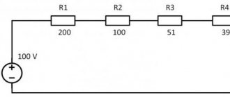
The outline looks like this:
Schematic diagram of current measurement in the circuit of a connected household appliance
1 – 220 volt socket.
2 – conditionally – household appliance.
3 – device power cable.
4 – circuit break points (connection of tester probes). In this case, they are shown on the phase wire, although this does not matter for checking the alternating current strength - they can also be at zero.
5 – multimeter set to 10 A AC current measurement mode
6 – multitester test leads.
It’s simple - after assembling such a circuit, you need to connect the power cable to the outlet, and then start the household appliance in the desired mode with the switch. And after 3–5 seconds (some devices require time to reach the nominal mode), take current readings in amperes.
But how can this be accomplished, so to speak, technologically? Cut the insulation and then cut one of the wires of the power cable to connect an ammeter to the gap? Sometimes they do this too. An example is shown in the illustration.
Agree, not a very attractive option. The integrity of the outer braid of the wire is compromised. The ends will have to be spliced and insulated after measurements. For a one-time urgent check, it might be fine, but nothing more.
Fence additional wires between the socket and the plug in order to “wedge” an ammeter between them? It's also quite inconvenient.
To make measurements safe and take a minimum of time and effort, you can make a special device. To do this, you will need a small plywood platform, two overhead (external) sockets (the cheapest) and a piece of power cord with a plug.
An easy-to-manufacture device for convenient and safe current measurement.
Two sockets are attached to a small rigid fragment (item 1), for example, plywood, textolite, etc., as shown in the diagram. We will completely arbitrarily number the sockets No. 1 and No. 2, and their contacts will be called 1a and 1b, 2a and 2b, respectively.
A power cord (pos. 4) with a plug (pos. 3) is connected to the sockets. This plug will plug into a regular power outlet.
The cord is cut, and its two wires are connected to the terminals of the same contacts of both sockets. That is, in the diagram these are 1a and 2a. And the second pair, 1b and 2b contacts are connected by a jumper made of a single-core wire.
How to take measurements with such a device?
- To begin with, a turn of the power cord is connected to an outlet (to any outlet or to the one being tested, that is, to the one to which the tested household appliance is permanently connected). After assembly, our entire structure is completely closed, insulated, and there are no exposed conductive parts.
- It makes sense to first check the voltage at the outlet. If the ultimate goal is to determine the real power of the device, then it is advisable to clarify this parameter. Sometimes, if the home network does not have a stabilizer, it differs significantly from the declared 220 volts. That is, it can affect the final result.
Checking the voltage is easy. The multimeter switches to ~V (ACV) mode with a range greater than 220 volts (usually 750 volts). The wire plugs are installed in the corresponding sockets of the device (COM and ~V). Then the probes of the device are inserted into the contacts of sockets 1a and 2a, as shown in the diagram below.
The first recommended measurement is the network voltage.
- After this, the power cord plug of the device being tested is inserted into one socket (any outlet). The circuit is not closed - it breaks at the second socket.
- The multitester switches to AC ammeter mode (~A or ACA) to the maximum range. The plug of the red test lead is moved into the corresponding connector.
Final diagram for connecting the load and multitester in the test fixture
- After this, the multitester probes are inserted into the sockets of the remaining free socket. And now all that remains is to turn on the household appliance being tested and take current readings from the multitester.
Charger for car battery
Before we talk about how to check amperes with a multimeter on a charger for a car battery, you need to know what it is for.
The optimal charging current for such a charger is 10% of the car battery capacity. A larger value will allow you to charge the battery faster, but will negatively affect the battery itself and significantly reduce its use time.
When purchasing such a charger in a store, all parameters are written on the charger itself. But such exercises, with minimal knowledge, can be done independently. In this case, a multimeter will come in handy. This measuring device will also come in handy if the charger fails.
It should be said that when measuring the current strength of any chargers, it is necessary to include any load (for example, a regular light bulb) in the circuit. Also, do not forget that the charger often produces direct current, so the multimeter handle must be set to the correct position (A-).
How to work
Before starting the story about how to measure current with a multimeter, it is necessary to give a number of recommendations on how to work:
First of all, you should study the instructions on how to operate such a device so as not to damage it. To confidently work with an electrical circuit, you need to practice using weak batteries - batteries. If you don’t have enough experience, strictly follow the instructions and learn all the functions of your multimeter:
This simple model is used by motorists when problems arise with charging the battery.