Checking the operation of circuit breaker releases
The main part of testing machines is checking the proper operation of their releases. Additionally, the quality of installation of switches, tightening of contacts, and compliance of protective equipment with design documentation are checked, but these parameters are already secondary.
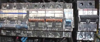
There are a large number of modifications of circuit breakers: air, modular, designed to protect motors, in a molded case. The most common are modular circuit breakers mounted on a DIN rail, so it would be advisable to consider the verification process using their example.
After one of the releases is triggered, the switch automatically performs its function - it turns off the power to a certain section of the circuit. The type of releases can be thermal or electromagnetic, but in modern equipment both types are most often used for the most reliable protection. Automatic machines with one type of release have a much narrower scope of application.
Automatic devices with thermal releases provide protection of the electrical network from line overload. This release is a two-layer bimetallic strip. When an overload occurs, this switch element becomes hot. Under the influence of temperature, the plate deforms, which leads to decoupling.
Electromagnetic releases are needed to protect the line from the destructive effects of short-circuit current. This element of the device is a solenoid with a movable core. The tripping mechanism is driven by a core, which is drawn in by a magnetic field created under the influence of short-circuit currents.
In turn, electromagnetic releases are divided into types depending on the time and current characteristics, that is, on how long and what currents take the switch to operate. The types of electromagnetic releases are designated in capital Latin letters. The most common types are those corresponding to the letters B, C, D.
In these elements, instantaneous tripping occurs within the following standard ranges:
- B - in the range from 3 times to 5 times the rated current;
- C - in the range of 5-10 times the rated current;
- D - 10-20 times the rated current.
At low starting currents, it is permissible to use circuit breakers with type B releases in the system. In the same network, it is advisable to install an input circuit breaker with characteristics C. The same devices can be installed in a network with moderate starting currents. Type D circuit breakers are suitable for protecting lines with high inrush currents.
GOST R 50345-2010 “Small-sized electrical equipment. Automatic circuit breakers for overcurrent protection for household and similar purposes” regulates how and which circuit breakers need to be tested.
Table 7 Time-current performance characteristics
The procedure for conducting inspections is approved in the regulatory documentation. Thus, the operation of electromagnetic releases is checked in accordance with PUE 1.8.37 by carrying out tests recommended by the manufacturer.
Our laboratory specialists use special equipment to perform tests, which allows them to successfully test electromagnetic, semiconductor and thermal releases, provided that In falls in the range from 16 to 320 A.
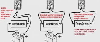
To carry out testing, the device's terminals are connected to the circuit breaker inputs. After this, current is applied and the time it takes before the release mechanism is activated is recorded. In this case, the test is carried out in stages:
- First, a current is supplied to the unheated device, which exceeds the rated current by 1.13 times. The thermal release must not operate within 1 hour with a rated current less than 63 A, and at least within 2 hours with a rated current greater than 63 A.
- Immediately after completion of the first stage, a current is supplied to the equipment that exceeds the rated value by 1.45 times. The release must operate within an hour at In 63 A.
- After completing the second stage, the voltage is removed from the switch and it is allowed to return to its original “cold” state. Next, a current is supplied to the device, 2.55 times greater than In. If In 32 A tripping should occur within 2 minutes.
To carry out all stages of the test, it is enough to turn on the Sine device and set the required current value in Amperes. After this, a timer is automatically activated, which is disabled after tripping.
Testing of circuit breakers with electromagnetic releases is carried out in the same way:
- A “cold” machine is supplied with a current of 3, 5 or 10 A, depending on its type (B, C, D - respectively). The instantaneous release must cause tripping in 0.1 second or more.
- The machine returns to a cold state, and then a current of 5, 10 or 20 A is supplied to it, also depending on the type of release. The device should operate in less than 0.1 seconds.
During the test, the current supplied to the device increases from a minimum value to an upper limit. This happens almost instantly. When the release is triggered, the current value at that moment and the time that has passed since the current reaches the required value are recorded.
How to test a circuit breaker for tripping
These guidelines define the procedure for checking the operation of circuit breaker releases in overload and short circuit modes in order to assess the quality of the circuit breakers and compare them with the standards of PUE clauses 1.7.79, 1.8.34; SNiP 3.06.06-85, section 4 and manufacturer’s data. The methodology was carried out on the basis of the requirements of GOST R 50571.16-2007 and PUE and is mandatory for use by electrical laboratory specialists in Krasnodar and the Krasnodar Territory of Energo Alliance LLC.
2.1 Measurement of insulation characteristics is carried out in accordance with the guidelines for measuring insulation resistance.
2.2 The volumes and timing of various types of tests, acceptable values of the characteristics of the equipment being tested are established on the basis of RD 34.45-51.300-97 and approved multi-year schedules.
2.3 Knowledge of these guidelines is mandatory for the following employees of the Insulation and Testing and Measurement Service: chief, engineer, electrician for testing and measurement.
3.
Test method for automatic circuit breakers
3.1 The measured value is the shutdown time of the automatic circuit breaker (AB) at a given current value exceeding the rated value.
3.2 Testing the performance of circuit breakers is carried out by loading them with primary current by creating an artificial short circuit with an adjustable current value in the circuit of the tested circuit breaker with measuring the shutdown time.
3.3 To carry out protective functions, AVs have maximum releases against overload currents and short circuit currents. Overload protection is provided by thermal or electronic devices. Protection against short circuit currents is carried out by electromagnetic or electronic releases.
3.4 Before measuring the shutdown time, check:
· compliance of the types and parameters of the AV with the design or passport for the electrical installation;
· compliance of current setting AB with the project;
· no visible damage to the AB,
· reliability of tightening of contact clamps AB;
· measurement of insulation characteristics;
· measuring the DC resistance of switch contacts.
3.5 Before measuring the timing characteristics, it is necessary to remove the voltage from all parts of the tested AV and take measures to prevent the supply of voltage to the place of work due to erroneous or spontaneous switching on of the switching equipment. Check that there is no voltage on live parts. Live parts that remain energized must be fenced; warning and instructional posters must be posted on the fences.
3.6 Measurement of the characteristics of a single-phase AV is carried out according to the diagram in Fig. 1.
The AB release being tested is connected to a loading transformer in the circuit of which a current transformer TA1 with a connected ammeter is installed. The second current transformer TA2 is connected to the current relay RT, the contacts of which break the stopwatch circuit. The primary winding of the loading transformer is connected to a 220V network through a control transformer. By changing the voltage on the control transformer, the current corresponding to the current setting of this type of AB release is set. At short circuit current and overload, the release must turn off. The AV response time is determined on the stopwatch scale.
3.7 Measurement of the characteristics of a three-phase AV is carried out according to the diagram in Fig. 2.
The AB release being tested is connected to a loading transformer in the circuit of which a current transformer TA1 with a connected ammeter is installed. The primary winding of the loading transformer is connected to a 220V network through a control transformer. By changing the voltage on the control transformer, the current corresponding to the current setting of this type of AB release is set.
The response time of the AB is determined on the scale of a stopwatch, the switch of which is the free contact AB.
3.8 When checking the characteristics of thermal and electromagnetic releases of automatic circuit breakers, a complete testing device “Saturn-M” or “Saturn-M1” and a load transformer NT-12 with a range of 30-12000 A are used.
3.9 Work with a device of the “Saturn-M” type in accordance with the “Technical Description and Operating Instructions” for this device.
3.10 When checking the characteristics of circuit breakers, other sets of equipment can be used corresponding to the specified current, voltage of the circuit breaker being tested and with an accuracy class of at least 0.5
4.
State assessment based on measurement results
4.1 Tests of circuit breakers are carried out in accordance with the requirements of GOST R 50345-92 by checking the time-current characteristics.
4.2 When checking the thermal release, a non-trip current AB is passed through all poles. In this case, the circuit breaker should not trip. Then, within 5 seconds, the current gradually increases to the value of the conditional tripping current. The circuit breaker must trip within the specified time. The current and time values are given in Table 1.
4.3 When testing AB from a “cold” state, a current equal to 2.55 In is passed through all poles. The opening time must be at least 1 s. and no more than: 60 s. at rated currents up to 32 A inclusive, and 120 s. at rated currents above 32 A.
4.4 When checking the instantaneous release of type “B” circuit breakers, a current equal to 3 In is passed through all poles for a period of at least 0.1 s. AB should not disengage. A current of 5 In is then passed through all poles and the circuit breaker must trip in less than 0.1 s.
4.5 When checking the instantaneous release of type “C” circuit breakers, a current equal to 5 In is passed through all poles for a period of at least 0.1 s. AB should not disengage. A current of 10 In is then passed through all poles and the circuit breaker must trip in less than 0.1 s.
4.6 When checking the instantaneous release of type “D” circuit breakers, a current equal to 10 In is passed through all poles for a period of at least 0.1 s. AB should not disengage. A current of 50 In is then passed through all poles and the circuit breaker should trip in less than 0.1 s.
Checking the IEK circuit breaker for authenticity
Weight of IEK machine;
- IEK VA 47-29 - 87 gr.
- IEK VA 47-29M weight 97 g.
- IEK VA 47-60 weight 105 g.
For comparison: A pack of cigarettes weighs 22-23 grams. A thin smartphone is 130-140 grams, a “thick” smartphone weighs 170-180 grams.
IEK marking is required in Latin IEK;
Old marking of IEK protection circuit breakers
The color of the stripe under the IEK logo must exactly match the color of the cocking lever;
New, correct marking of IEK circuit breaker
There is a high probability that the IEC machine is counterfeit
Information about the machine and the address of the manufacturer’s website must be stamped on the case;
The inscriptions and diagram of the machine must be clearly visible on the front of the case.
conclusions
Unfortunately, the findings are disappointing. It is impossible to visually check the serviceability of a circuit breaker when purchasing it 100%. But this does not mean that this should not be done. Be sure to buy automatic electrical circuit devices in specialized stores, exclude hardware stores and hypermarkets. When purchasing, carry out a visual inspection of the machine and, based on the obvious signs described in this article, check the machine for authenticity.
Malfunction of the circuit breaker in the panel
Electrics are good as long as they work properly. Any electrical fault baffles most people on the planet. In this article we will look at how to determine a faulty circuit breaker and how to eliminate it.
By the way, not only in electrical matters everything does not always work as it should. Repairing the equipment that helps us is the same work process, we just need to be prepared for it. This also applies to road construction equipment. A reliable supplier of spare parts with a wide range of spare parts for most global manufacturers will help you in the repair of road construction equipment. Where can I find it? Try it on the website arsenal-zapchast.ru. You won’t regret it, there are spare parts for 13 brands of leading manufacturers of road construction equipment.
Circuit breaker and short circuit
I'll start from the beginning. A circuit breaker or circuit breaker is designed to protect the electrical wiring (cables and wiring wires) of a room from short circuit and overload. A short circuit leads to the instantaneous occurrence of overcurrents in the electrical network (currents that are orders of magnitude higher than operating currents).
Any overcurrent, and in residential circuits this is 1.8-12.6 kA, according to the laws of physics, leads to the release of colossal thermal energy. More than one household contact cannot withstand this energy, and at the point of the short circuit a flash or so-called electric arc occurs. If you do not quickly turn off the power supply to the emergency network, then there is a very high probability of a fire, and even worse, injury to a person due to short-circuit overcurrents.
Loading method
During loading, the main characteristics of the machines are measured (rated current, protection operation current, protection operation time under abnormal conditions) on a special installation. All work on testing the functionality is carried out by special personnel who have access to such tests, with a certificate with a mark of admission to special work on testing electrical equipment.
The certificate must indicate the safety group and the voltage at which the employee can conduct tests (up to or above 1000V). The certificate must be signed by the chief power engineer of the enterprise that carries out the verification work. The method of loading AV in the factory must comply with GOST for low-voltage control and distribution equipment.
Switch testing devices
The complexes used to test switches are specially designed for this purpose. An exception is the RETOM series devices, which are originally intended for testing relay protection, but can also be used to supply currents to the contact system of the circuit breaker with control of the moment of shutdown.
RETOM-21 is most suitable for this purpose. Testing the operation of the thermal release is carried out by applying a continuous current simultaneously with starting the device’s stopwatch, configured to record the disappearance of the current during shutdown. Electromagnetic releases are tested by currents supplied by pulses of duration set by the user. With a gradual increase in current, the overload protection of the machine will inevitably trip.
An important advantage of RETOM is that the current supplied for testing is sinusoidal. Most other devices specially designed for testing machines produce a pulse current generated by thyristor regulators. But their dimensions are smaller and management is simpler.
There are many such devices. To check the cutoff, they also supply current with increasing amplitude pulses of adjustable duration, and to check thermal protection, the required current is set and the stopwatch is started.
Circuit Breaker Preventive Maintenance, Inspection and Testing
Preventive maintenance depends on operating conditions. Initial checks will be aimed at identifying particulate matter contaminating the internal workings of the device. Particulate buildup can usually be disposed of by flipping the "Off" and "On" switch to clear the accumulated dust.
Circuit Breaker Trip Test
By analyzing the current drawn by the trip coil while the circuit breaker is operating, it can be determined whether there are mechanical or electrical problems. In many cases, such problems can be localized and used to find the root cause.
Insulation resistance test
To test the resistance of the circuit breaker, the load conductors and lines must first be disconnected. If they are not disconnected, the test values will also include the characteristics of the connected circuit. Resistance testing is critical to verify that the insulating material is performing correctly. An instrument known as a megohmmeter is used to test the insulation resistance. The instrument applies DC voltage to a wire for a specified period of time to test the resistance within the insulation on a specific wire or winding. It should also be noted that if you turn on a voltage that is too high for the insulation to withstand, you can potentially damage the insulation.
Connection tests
Checking the connection is important to ensure proper electrical connections and to recognize signs of overheating. It is important that electrical connections are installed correctly to prevent and reduce overheating.
Contact resistance test
Normal contact wear occurs after prolonged use. A simple way to determine signs of weakening inside a breaker is to evaluate the resistance at each pole. Signs of abnormalities within the device, such as erosion and contact contamination, are obvious if there are excessive millivolt drops across the switch. Testing contact resistance is important to determine whether the instrument is serviceable.
Overload trip test
Overload tripping components can be tested by injecting 300% of the breaker rating into each pole of the circuit breaker to determine whether it will respond automatically when tripped. The goal is to make sure the circuit breaker is working correctly.
How to check a differential machine
Unfortunately, testing such important characteristics as response time, overload characteristics, and short-circuit current with automatic devices at home will not work. Since to check these parameters it is necessary to have special instruments and equipment.
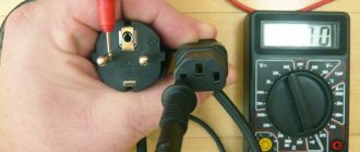
The difference between a difavtomat and an RCD
For the home, it is quite enough to check the differential circuit breaker for operation and compliance with the leakage current protection, at which the circuit breaker turns off and provides protection against electric shock. A differential circuit breaker differs from an RCD device only in the presence of a circuit breaker. That is, this is the same RCD plus an automatic device in one housing. Therefore, all checks for the suitability of a difavtomat are similar to testing an RCD.
Types of automatic machine checks
There are several ways to check the functionality of protective devices, these are:
- Check with the “TEST” button located on the device body.
- A regular battery from 1.5 V to 9 V.
- A resistor that simulates a violation of the insulation resistance of electrical wiring and household appliances.
- A simple permanent magnet.
- A special electronic device for checking the parameters of differential circuit breakers and RCDs used in industry.
Before purchasing a security device, you need to know what tasks it will perform. For fire-fighting purposes, the difavtomat and RCD are selected with a leakage current of 300 mA. If protection against electric shock is required, a device with a leakage current of 30 mA is used. In damp and damp bathrooms or baths, protection with a leakage current of 10 mA is required.
Check with the "TEST" button
This button is located on the front side of the differential machine. Before checking the functionality of the device, it is connected to the network. When you press the “TEST” button, the protection turns off the network. The “TEST” button simulates leakage current, as if the integrity of the wire insulation is broken.
Test button test
By pressing this button, the neutral wire of the input terminal and the phase wire at the output of the device are short-circuited through a resistor rated for a current of 30 mA (or other leakage current indicated on the machine). The protection device is switched off and provides a protective function. This check can be done without load. The differential machine can be electromechanical or electrical, the main thing is to connect it to the network correctly.
Battery test
Such devices are tested with a 1.5 V - 9 V battery with a leakage current rating of 10 - 30 mA. A device with a lower sensitivity of 100 - 300 mA from a battery will not work. A protection device with characteristic A will operate from a battery connected to the terminals of any polarity.
And for devices with an AC characteristic, the battery is connected with one polarity; if the device does not work, you need to change the polarity of the battery (minus to the output of the device, and plus to the input). Only electromechanical RCDs are tested in this way.
Checking leakage current with a resistor
The leakage current of the differential circuit breaker is checked with a resistor connected at one end to the input of the neutral wire and the other to the output of the phase terminal. For RCDs with leakage currents of 10 mA, 30 mA, 100 mA and 300 mA, the resistor is calculated using the formula: R = U/I Approximate value of resistors for different leakage currents: 10 mA -22 kom, 30 mA -7.3 kom, 100 mA - 2.2 kom and 300mA - 733 ohms.
When checking for response current, one end is connected to the phase output terminal, and the other to the neutral wire input terminal. The RCD must be connected to the network (no load required). When the resistor is connected in this way, the protection should work. Sometimes the differential machine does not work. This is due to some variation in resistor values.
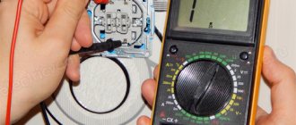
The leakage current is visually checked by connecting a variable resistor in series (for a leakage current of 30 mA) 10 kΩ with a multimeter with an AC scale of 100 mA. It is advisable to take a multi-turn resistor for a smooth change in resistance.
Connect a resistor with a multimeter, apply the network to the differential circuit breaker and smoothly rotate the resistor knob from the maximum to detect the current at which the protective device turns off. Next, measure the resistance of the variable resistor; it should be approximately 7.3 kΩ for a leakage current of 30 mA. This measurement method is suitable for electromagnetic and electronic devices.
Testing permanent magnet protection
You can only check the electromechanical protection device with a magnet; the electronic device will not work.
This is explained by the fact that when a magnet is brought to one of the sides of the RCD, a constant electromagnetic field acts on the differential transformer and causes a potential imbalance at the output of the machine, the protection is turned off. Electronic devices do not have such a differential transformer.
Checking circuit breakers
Why is it necessary to check circuit breakers with voltages up to 1 kV?
The main task of circuit breakers is to protect electrical circuits up to 1 kV from critical operating conditions caused by insulation failure. Switching protection applies to AC distribution networks and electrical receivers. The safety function operates due to an electromagnetic release against maximum overload currents and short circuit currents. What is the purpose of testing circuit breakers with voltage? First of all, diagnostics must be done to determine the technical condition, because only a working device will work in an emergency. The second point for which circuit breakers up to 1000 V are tested is to obtain data on the compliance of the declared and actual characteristics.
Loading machines
Circuit breakers are used to protect electrical installations from short circuits (short circuits) and overloads. The Tekhnoprom Zamer laboratory offers inspection and testing services for automatic machines.
The essence of the tests is to measure factory characteristics and check them for compliance with established standards. In other words, this is a measurement of the passage of currents through the circuit breaker before it is completely tripped. This method is called loading machines.
The laboratory tests circuit breakers controlled by differential current, residual current devices and switches with thermal and electromagnetic releases. Thermal releases are triggered by overload currents. Electromagnetic - from short circuit currents; in addition, most modern circuit breakers are equipped with electronic units with adjustable settings for current and response time. In any case, the circuit breaker is checked to ensure compliance with factory specifications.
Tests for loading circuit breakers are carried out using a special device UPTR-2MC.
Test circuit for circuit breakers.
Our laboratory specialists will also check the automatic transfer of reserve (ATS), which will guarantee the stable operation of your equipment and the continuity of the work process in emergency circumstances.
Circuit breaker testing cost
NAME OF WORK UNIT OF MEASUREMENT Price
| Circuit breaker testing | 1-pole circuit breaker | 80 rub. |
| 3-pole circuit breaker: | ||
| up to 50 A | 150 rub. | |
| up to 200 A | 220 rub. | |
| up to 1000 A | 550 rub. | |
| > 1000 A | 850 rub. | |
| Check and test the differential circuit breaker (RCD) | device | 120 rub. |
The service can be ordered by phone or in person with company employees.
When are the tests carried out?
The performance of the entire circuit depends on the correct operation of the machines. To exclude false alarms or failures in operation, periodic testing is required. Checking the operation of switches is carried out:
- When the equipment is put into operation for the first time (acceptance tests).
- After performing routine or major repairs (or an emergency).
- For prevention purposes.
- While using the equipment.
Our advantages
Experienced engineers
- Our employees have many years of testing and measurement experience.
Full reporting
- We will provide a complete picture of the equipment being tested
Professionalism and experience
- Few companies have a detailed understanding of the nuances of electrical measurements
Modern equipment
- We carry out measurements using modern equipment, this allows us to obtain high quality and increase the speed of measurements
Free consultation
- Our specialists will advise on any questions.
Test frequency
The rules for technical operation of consumer electrical installations (PTEEP) do not have a clear time frame for testing circuit breakers. During operation, the protective characteristics of the switches are checked according to the standards established by the equipment manufacturer. For consumers, deadlines are approved by the technical director of the organization. The recommended frequency of testing for loading machines is once every 3 years. This frequency of checks will help prevent failure of the switching device and damage to the electrical circuit.
Work order:
- Studying the electrical installation diagram.
- Checking compliance of installed AVs with project documentation.
- Removing the supply voltage.
- Visual inspection.
- Checking the mechanical part of the AB for five-time manual switching on and off with monitoring of contact closure.
- Assembling the measuring circuit in accordance with the one shown in Fig. 2
- Supplying voltage to the AB test device.
- Setting the required current before the circuit breaker trips.
- Recording the readings (current and response time) of the circuit breaker.
- Issuance of test reports (technical report).
Source: https://t-zamer.ru/uslugi/progruzka-avtomatov/
Checking the RCD by pressing the “test” button
The most common and safest way is to check the functionality of the RCD using the “Test” button located on the body. This type of testing does not require special knowledge and can be performed independently by anyone. The button itself is indicated by a large letter “T” or the word “TEST”. With its help, cases of current leakage past the RCD are simulated.
The leakage current rating is set by a special test resistor built into the device. The current flowing through it should not exceed the value of the differential current for which the device itself is designed. Based on this, a resistor with the necessary parameters is selected. If the connection to the electrical network is correct, the RCD is triggered immediately after pressing the testing button, regardless of the presence or absence of a connected load. For everyday conditions, such a check is considered quite sufficient.
The recommended frequency of inspections is once a month. The effectiveness of the tests is achieved by simulating a real current leak, to which the device responds by instantly shutting down.
Method No. 1 - TEST button
The easiest way to check the RCD for operation with your own hands is to use the TEST (“T”) button installed on the front panel, as shown in the photo below. In this case, you just need to press the button with your finger, as a result of which a leakage current will be simulated and the protection should work.
If after pressing the tester the shutdown does not occur, this indicates the following:
- You may have made the connection incorrectly, as the test result showed. In this case, we recommend that you read the instructions for connecting a residual current device yourself.
- The button doesn't work. It happens, it happens that the RCD itself works, but the leakage current simulation is faulty. In this case, even if the connection is correct, false positives will not occur during testing. You will need to check the protection yourself using one of the alternative methods that we described below.
- The automation is faulty. Again, it will be possible to verify whether the RCD is working or not only after another, more complex check.
Video instructions for checking for serviceability yourself