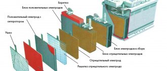
Design and arrangement of electrical cables
A heated floor system, mounted from an electric cable or using infrared film, consists of a number of elements:
- heating cable, which is a source of thermal energy;
- a temperature sensor that records the degree of heating of the wires;
- a thermostat responsible for connecting all the component elements into a common structure and regulating the switching on/off of the floor in accordance with the heating temperature of the cable.
The thermostat or thermostat looks like a small switch. It is intended to adjust the voltage that is supplied to the wires. Connect this device to a standard electrical network using phase and neutral wires.
The thermostat regulates the voltage automatically. It is supplied directly to the heating cable after the floor in the room has cooled. The degree of its heating is monitored by a temperature sensor, which is mounted near the wires and filled with cement mixture.
Residents independently set the temperature at which the floor surface heating system should turn on. The cable used to equip such a heating structure can be resistive and self-regulating. The latter of them independently reacts to temperature fluctuations and changes the resistance level. In turn, a resistive cable does not have such functions.
When calculating the operating parameters of the heating system, and during installation, one must not forget that the length of some types of cables must be certain. If they are shortened, then the degree of heating and current readings may change, as a result of which the wires will begin to function incorrectly and the insulation on them will begin to deteriorate.
When arranging the system, either a single two-core cable or two single-core cables are used, which are arranged in parallel. The first of them is a mesh of wires with a plug on one side. It is unacceptable to cut it and lay it in a screed in places where large pieces of furniture or equipment will be located.
In turn, single-core cables can be cut and nothing bad happens to the insulation. In the same way, infrared floors are trimmed in accordance with the area of the room that requires heating.
Malfunctions in the floor heating system - why it doesn’t work
It happens that after the installation is completed and everything is connected, the heated floor does not work - how to check why? If there is no heating, it means that an error was made during the installation process or that unsuitable equipment was used.
Before checking the serviceability of the heated floor, it would not hurt to find out about the main errors that occur in its elements:
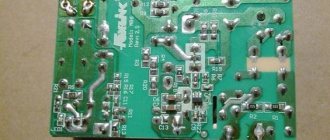
- Thermostat . Malfunctions of the heated floor thermostat occur as a result of the failure of the capacitor or relay. Since its repair is expensive, it is much easier to replace the device with a new product. The main thing is to find out which company made it. Both the temperature sensor and the thermostat must be from the same manufacturer. Sometimes it is not clear why a warm floor does not heat well, but as a result it turns out that the thermostat is simply not configured correctly or is not working correctly.
- Thermal sensor . If necessary, it can be easily replaced. Depending on the quality, this device can work for both a long and short time. The service life is affected by correct installation. To make sure it is working, you need to know how to check the heated floor temperature sensor. This device must be placed inside a corrugated tube and installed in a certain place and at a specific angle in relation to the wires.
- Cable . It only deteriorates if installed incorrectly. Its most vulnerable part is the coupling.
In order to less often solve the problem of how to check an electric heated floor for malfunction, and not often have to repair it, you should buy equipment from time-tested manufacturers.
Malfunctions of heated floors
And now, it would seem, the system is installed, everything is connected, but for some reason the floor does not want to become warm. If heating does not occur, it means that somewhere during installation an error was made or faulty equipment is used in the system.
Table. The main causes of floor heating malfunctions.
| Floor element | Malfunction |
Electronic thermostat for heated floors
Advice! To avoid having to frequently repair the underfloor heating system in your apartment, it is recommended to purchase reliable equipment from trusted manufacturers.
Fault detection methods - how to check correctly
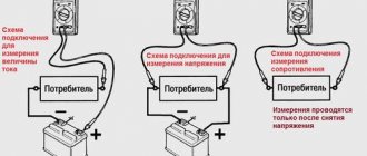
There are two ways to check the functionality of the system:
- First . It consists of visually inspecting the cable and components for damage. But it allows you to detect only visible defects, such as burnt equipment, lack of power supply in the building, broken cable and others. But this method is not very informative, and it is not always possible to identify the reason for the lack of heating.
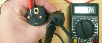
- Second . This method makes it possible to find a breakdown using a multimeter. It allows you to find out the voltage in the network. Before checking the heated floor with a multimeter, the temperature regulator is removed from the wall and the voltage, which should be 220V, is measured using special probes. If this parameter is normal, then the cause of the malfunction lies in one of the system elements.
First of all, perform a visual inspection to make sure there is power supply to the floor. Next, they look for melted or burnt parts. If nothing can be detected, use a multimeter.
You need to measure the cable resistance and divide it by 220 to get the voltage value in the electrical network. This value reflects the amount of current passing through the system. This figure is then multiplied by the voltage to determine the power consumption. It is necessary that it corresponds to the power of the heating system, which is reflected in the passport.
When the received parameter is greater, this means that the cable insulation is damaged. If the value is less than that specified in the passport, then you need to read the instructions on how to check the heated floor for a break. In the absence of documentation for the equipment, it is considered that the power is conditionally 150 W/m2.
If the resistance of the heated floor on the multimeter is zero, then the system is disabled by a short circuit. In this case, equipment repair will be expensive, and it is difficult to find such damage on the cable field. If heating occurs using infrared flooring, you need to lift the floor covering, find the damaged area and replace it.
How to check a heated floor without a thermostat and a multimeter?
If it happens that you don’t have a multimeter at hand, then the test can be performed without it.
The integrity of the heating core can be checked by applying a voltage of 220V for a few minutes.
A working cable will become warm. The integrity of the insulation between the heating core and the grounding screen can be checked by connecting the section to a power line that is equipped with a current leakage protection device (RCD).
If the RCD does not work, then the heated floor is working. However, such a check should be carried out only in the absence of measuring instruments.
If you still have questions: how to check a heated floor without a thermostat? How to check a heated floor with a multimeter? This site offers free consultation from specialists.
.
Contact our managers, they will be happy to answer all your questions.
You can find phone numbers on any page of the site or order a “call back”.
The site also offers a large selection of heated floors at an excellent price. Believe me, we have the best prices.
Happy shopping.
Checking the heated floor upon purchase and after installation
The heated floor is checked upon purchase, before pouring, or if the cable breaks for repair.
The first check of the heated floor with a multimeter is carried out at the time of purchase. The seller is obliged to demonstrate all the functionality of the product at the request of the client. The product must be accompanied by documentation with the specified technical characteristics, insulation resistance values and mats. This data must be checked against the actual readings of a tester or multimeter.
After laying the heating elements, but before installing the floor covering or pouring the screed, it is necessary to check the operation of the heated floor a second time. To do this, you first need to make sure that the heating cable is intact. Then the system is connected to the mains and the operation of different modes is observed for some time. At this stage, it is important to ensure that the temperature sensor and thermostat are functioning correctly. Correct operation requires uniform heating of all sections of the cable. The heating temperature of the elements must change in accordance with the specified parameters of the thermostat.
If a malfunction is discovered during the installation process, it is best not to look for the problem or try to solve it, because This is most likely a warranty issue. You should contact the store where you purchased the product and replace it with a working version.
Measuring resistance with a multimeter
If there are no violations, the multimeter reading should be equal to unity.
When ceramic tiles are chosen as the floor covering, until the screed and tile adhesive are completely dry, the heating cable of the system must not be connected to the network. To make sure the device is working, you need to use a special device - check the heated floor with a multimeter:
- The device is set to resistance measurement mode and the limit is set to 2000 Ohms. Make sure you set up the multimeter correctly. To do this, you need to short-circuit its probes - zero should appear on the screen.
- Find the heating cable and measure the resistance between its cores. The result was 409 ohms.
- Compare the result obtained with the data specified in the device passport. It should be taken into account that the resistance of a heated floor may depend on the ambient temperature and cable length. The permissible error is considered to be a difference in measurements of 10-15%. In this case, the user manual indicates a resistance of 360 ohms. The difference between the measurement and the value written in the document was 14%, which is considered acceptable.
- The resistance of the insulating material is measured. Switch the multimeter to 2000 kOhm mode, and ring each cable core. The instrument readings should tend to unity, which confirms that there are no violations of the integrity of the heating element braid.
It is advisable to carry out a trial check at all stages of working with heated floors. When purchased in a store together with a sales consultant, then after installing the system, pouring the screed and laying ceramic tiles.
How to check the resistance of a heated floor with a multimeter before installation?
The heated floor is checked for the first time before installation ( photos No. 1 and No. 2 or video at the end of the page
), the integrity of the heating insulation element is determined using a multimeter.
The multimeter is set to resistance measurement mode and the limit is set to 2 KOhm. If connected correctly, the device will show 0 if its probes are shorted.
Each heating cable package indicates its resistance (photo No. 3). We take measurements between the power cores. (photo No. 2). The resulting value was 178 Ohms, and the passport data is 176.3 Ohms.
The resistance value may change depending on the temperature, but for a working cable it is no more than 15%.
To check the integrity of the insulation, we move the device to the position of measuring the maximum possible resistance.
On our device it is 2000 MOhm.
The value, when measuring any of the cores with a grounding screen, in a working product tends to unity. (photo No. 3)
However, to correctly measure insulation resistance, it is necessary to use a device that allows you to measure at high voltage (megger).
What is included in underfloor heating?
Heated floors are made of electric cables or with infrared film. The system includes the following elements:
- Heating cable – heat source;
- Thermal sensor for monitoring cable heating;
- The thermostat, which connects the elements into the structure, starts or turns off the heating depending on the temperature parameters.
Features of using a thermostat
The thermostat automatically adjusts the voltage supplied to the wires. It connects to a regular electrical network through phase and neutral wires and looks like a small switch. Its heating is monitored by a sensor located next to the wires.
The person sets the minimum temperature, upon reaching which the heating system starts. A cable in this design can be resistive or with self-regulation of fluctuations in heat degrees and resistance levels.
Which cable is suitable for the heating system?
Calculations of the heating system largely depend on the length of the cable, changes in which will subsequently disrupt the functioning of the entire structure and damage the insulation.
Two-core cables or a pair of single-core cables are used. A wire with two cores cannot be cut or installed in places with floor loads; single-core wires are more versatile.
Main malfunctions of heated floor elements
The launch of the installed system can be unsuccessful, although everything is done according to the rules. If the floor does not heat up, the fault may be in one of the system elements.
Thermostat
This element may be inoperative due to a capacitor failure or relay failure. Repairing this part is expensive; it is more rational to buy a new one, preferably from the same manufacturer. It is important to ensure full compliance with the manufacturer for the thermostat and sensor.
Thermal sensor
A faulty temperature sensor is easy to replace, since its service life depends on the quality of manufacture by the manufacturer and correct installation. To check the functionality, you need knowledge about testing a temperature sensor for heated floors.
Control temperature measurement is carried out in a corrugated pipe installed at an angle to the surface in a certain place.
Cable
The wire can be damaged by improper installation; a malfunction of the coupling is especially often detected. To avoid problems with the cable, work should be entrusted to professionals with extensive experience.
Troubleshooting underfloor heating using the ringing method
You can ring the heated floor with a multimeter. To do this, you need to set it to the sound signal mode, which starts next to the scale of the built-in ohmmeter. As soon as the probes of the device touch each other, the specialist hears a sound.
This signal means a closed circuit. If the probe touches the conductors of heated floors, the sound becomes an intermittent buzzer.
The absence of sound indicates a faulty core, its tear. As soon as the floor ringing work is completed, the procedure is repeated with a temperature sensor. If the test results differ from those indicated in the passport, then the sensor is faulty and the system cannot fully operate.
Professionals with experience in installing heated floors strongly recommend not to skimp on materials and equipment, so as not to troubleshoot one of the structural elements.
Diagnostics of the thermostat using a light bulb
You can diagnose the operation of the thermostat using a simple light bulb.
To do this, perform the following actions:
- terminal N with the neutral cable of the thermostat is connected to the network, and terminal L to the phase one;
- connect a light bulb to the sensor, which will serve as an indicator;
- Having set the maximum heating, turn on the device. If the light comes on after this, it means the regulator is working properly.
There is another way to check the performance of a heated floor:
- completely turn off the electricity in the room by snapping off the plugs on the panel;
- connect the heating system wires bypassing the thermostat to the electrical panel;
- turn on the power supply, wait 25-30 minutes, see if the floors are heated.
If, with such a direct connection, the floors become warm, then this indicates a malfunction of the thermostat.
To check the serviceability of the heating cable, you need to measure its resistance using a multimeter.
How to check the functionality of the thermostat
Malfunctions of the thermostat can be associated both with the device itself and with the remote temperature sensor.
When the thermostat fails, most often the relay or capacitor is to blame. Considering the cost of repairing it, it is more advisable to purchase a new thermostat. To check the functionality of the thermostat you must:
- set the minimum temperature on the thermostat;
- apply voltage to the thermostat and measure it (should be 220 V);
- move the toggle switch to the ON position;
- Set the thermostat to the maximum temperature. When the temperature rises, a click is heard from a working thermostat (the relay switches). The voltage at the load contacts (wires going to the heating elements) should be 220 V.
- when the thermostat is set to the minimum temperature, the relay is activated again, cutting off the voltage supply to the load contacts.
Sensor malfunctions
The sensor works in conjunction with a thermostat and measures the temperature of the heated floor. If the floor heating turns off quickly or severe overheating is observed, then you need to check the sensor.
A visual preliminary inspection of the sensor may reveal the presence of:
- burnt contacts;
- lack of system power.
You can also determine the voltage level at a certain section of the circuit. The sensor is a resistor with its own resistance. The readings obtained from testing with a multimeter can provide valuable information about the breakdown.
With their help, you can determine which of the sensor elements (relay and capacitor) has failed or the connections are inaccurate.
Diagnostics with the device is carried out after inspection. To do this, you need to turn off the thermostat, remove the panel from the front side, then remove the installation block. Connect both terminals with a voltage of 220 W to the thermostat.
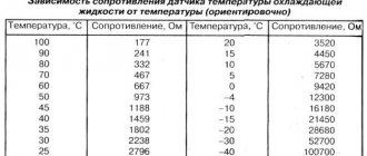
The document for the thermostat indicates the resistance of the device; usually it ranges from 5 kOhm to 120 kOhm, which depends on the body temperature of the sensor. When 5 ⁰C, its value will be about 22 kOhm, and at 40 ⁰C – 6 kOhm.
The multimeter is set to ohmmeter mode. If the indicators coincide with those declared by the manufacturer, then the sensor is working.
Therefore, independent testing of a heated floor is possible using a multimeter.
In a household with heated floors, the owner needs to have a device to check the functionality of the sensor and thermostat with heating cables.
Modern thermostats are equipped with touch screens; they can independently indicate sensor failure.
How to check the temperature sensor
If the floor itself is working, but the system still does not work, then the reason lies elsewhere. You can try to check the serviceability of the sensor. It is a resistor that has its own resistance, and this can also be measured using a multimeter. But the performance of the latter varies greatly depending on what the floor temperature is at the moment. For example, with a temperature reading of 5 degrees, the multimeter will show a value of 22 kOhm, and with a temperature reading of 40 degrees – only 6 kOhm. In general, the indicator should correspond to the factory resistance. If it differs from the indicated value by more than 5 kOhm or is equal to 0, then the sensor does not work and needs to be changed.
Warm floor sensor
How can I replace the temperature sensor?
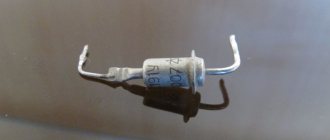
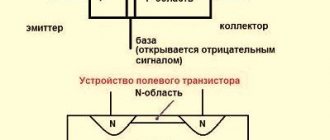
The temperature sensor used in thermostats for heated floors is a thermistor with a negative TCR (temperature coefficient of electrical resistance). This means that when heated, the resistance of the sensor decreases.
The second parameter required to select a temperature sensor is the resistance value under normal conditions, at 20°. The resistor value is usually indicated on the thermostat body next to the temperature sensor connection terminals or in the product data sheet.
To select a temperature sensor, this data is quite sufficient. The only thing that is difficult to find out and select is the TKS characteristic, that is, the change in the resistance value of the temperature sensor due to changes in ambient temperature.
But this is not a critical parameter; anyway, the temperature on the thermostat is set experimentally. After all, the temperature sensor is installed in the floor and the set temperature on the thermostat sets the floor heating temperature, and not the room temperature.
How to determine the resistance of a temperature sensor
The temperature sensor of the SPYHEAT ETL-308B thermostat has failed. Its technical characteristics were unknown. They had to be determined experimentally.
To do this, external circuits were connected to the thermostat, in accordance with the diagram printed on its body - supply voltage was applied, an incandescent light bulb was connected instead of heating elements, and a variable resistance was connected instead of a temperature sensor.
I had a resistance magazine available, so I decided to use it for calibration. The resistance magazine is a box in which high-precision resistances are placed and there are switches with which you can set the desired value.
Consistently setting the regulator knob to positions from 20° to 30° and changing the resistance value with the knobs in the resistance magazine until the thermostat operates, I built a sign.
Dependence of the thermostat response on the resistance value of the temperature sensor
| Temperature set on the thermostat, °C | Turn-on resistance, kOhm | Turn-off resistance, kOhm |
| 20 | 16 | 14 |
| 25 | 10 | 12 |
| 30 | 8 | 9 |
| 35 | 6 | 7 |
Based on the data in the table, for this heated floor thermostat, a thermistor with a negative TCR of 10 kOhm is suitable as a temperature sensor. The resistance value of the resistor when turning the light bulb on and off turned out to be different due to hysteresis in the thermostat itself. This is necessary so that the heating element of the warm floor turns on less often.
Determining the temperature sensor rating can also be done using a 47 kOhm variable resistor. You just have to disconnect the thermostat from the network every time after turning the light bulb on and off and measure the resistor resistance with a multimeter.
You can do without measurements. It is enough to have several constant resistors with values ranging from 10, 15, 20 and 30 kOhm. Resistors are connected in turn instead of the temperature sensor. By rotating the thermostat knob, you need to determine which resistor the light bulb will turn off and on at a temperature of about 20°C.
Thermistor selection
You could buy it ready-made, but to do this you had to place an order online and wait for delivery. In addition, the price of the issue reached 20% of the cost of the thermostat itself.
Therefore, it was decided to make a temperature sensor from available thermistors. There was a thermistor with a nominal value of 10 kOhm with a negative negative TKS type MMT-4. I decided to use it for repairs.
For connection there was a piece of wire with which the failed temperature sensor was connected. In principle, any wire can be used to connect the sensor, as long as it can withstand a temperature of at least 100°C. To check, the ends of the wires were stripped and wound onto the thermal resistance terminals.
Next, the thermistor was located in close proximity to the incandescent light bulb connected to the terminals for connecting the heating element of the heated floor. Supply voltage was applied to the thermostat.
After a few minutes, the light bulb heated the thermistor, its resistance decreased, and the thermostat turned off the voltage supply to the light bulb. When the thermistor cooled down, the light came on again, and this continued ad infinitum with a period of several minutes.
After checking the operation of the heated floor thermostat, wires were soldered to the MMT-4 thermistor with soft solder and pieces of insulating tube were put on the soldering points.
For reliability, you can put a heat-shrinkable insulating tube on the thermistor. A homemade temperature sensor was installed during the installation of a heated floor and showed stable operation.
As you can see, even without experience in repairing electrical appliances, you can repair a thermostat for a heated floor with your own hands at home, including making a temperature sensor from a standard thermistor.
Attention, the electrical circuits of thermostats are galvanically connected to the phase of the electrical network. Touching exposed parts of a circuit connected to an electrical outlet may result in electric shock.
How to check the functionality of the thermostat?
Let's look at an example of how you can check whether the thermostat is working using an ordinary light bulb.
Step 1. The thermostat is connected to the network in compliance with all rules. That is, the phase wire is connected to terminal L, and the zero wire is connected to terminal N. A temperature sensor and a regular light bulb screwed into the socket are also connected. It will serve as a load indicator.
Connecting the thermostat
The light bulb will serve as a load indicator
Step 2. The thermostat connected to the network is turned on using a toggle switch.
The thermostat turns on
Step 3. The lever responsible for increasing the temperature is set to maximum.
The maximum temperature is set
Step 4. If the thermostat is working properly, the light will light up.
The light came on
Step 5. Using this circuit, you can also check the temperature sensor. To do this, take it in your hand, and the temperature regulator is set to the average value.
Using this circuit you can also check the temperature sensor
Step 6. The temperature control is turned again to higher values. The light will come on again. But when the sensor heats up to the temperature of the human body, it will go out.
The light came on again
Step 7. After this, the system can be left alone. After some time, the light will light up again when the temperature sensor cools down and sends a signal to the thermostat.
The light came on again
If the readings are the same
If the readings for both wires are the same and within 10% of the total wire length (refer to product specifications or manual), everything may be ok. However, it could also mean that the break is at the far end of the wire. The most common fault in this case is a damaged terminal connection (at the end of the wire).
If the readings obtained are the same, but the distance value is less than the factory wire length.
This may indicate a complete break in the heating cable in the heated floor.
Example 1: For example, a 25 square foot NADWM-120-350 mat has 100 feet of cable and 15 feet of mat length. If the OTDR reading is less than 30.5 meters, there may be a complete break in the wire.
Example 2. If mats of other dimensions are used, the cable length per 1 square meter can be checked with their manufacturer, or calculated independently. For example, the most common are mats with a width of 50 cm and a wire pitch of 8-10 cm.
By simple calculations, you can approximately determine the length of the cable in a mat 2 m long (area 1 sq. m.) L cable = 10.5 m. To accurately determine the location of the heating cable, you can use the 701K-G test kit:
- Connect the red lead to one (or simultaneously two) conductors of the heating cable
- Connect the black lead to the metal sheath of the heating cable
- Switch the generator to Tone mode (in this mode the generator supplies a signal to the cable)
- Using an inductive probe, we determine the location of the cable by the maximum value of the received signal. To avoid errors, you should reduce the sensitivity of the device to the minimum level at which the signal will be heard.
If the OTDR reading is less than the actual cable length, there may be a complete break in the wire.
Check the readings with an ohmmeter or multimeter:
- Between black and white wires: see factory settings. Typically, when selecting a 200 ohm scale, the reading should be between 20 and 200 ohms. If there are no readings, this confirms a cable break. Before jumping to conclusions, double check the batteries on your meter and take the measurement again. Use a digital ohmmeter (with a digital display) rather than an analog one (with a dial indicator).
- Between black wire and ground: No reading should be displayed. If there is a reading, then there is a “ground fault”, that is, a “short circuit”. The OTDR should show the distance to the fault on that wire and indicate "Short".
- Between white wire and ground: No reading should be displayed. If there is a reading, then there is a “ground fault”, that is, a “short circuit”. The OTDR should show the distance to the fault on that wire and indicate "Short".
Determine the side with a cliff
Using an ohmmeter, determine which side (towards the thermostat or towards the end of the mat) the break is relative to your cut. Twist the black and white wires together on the thermostat using a jumper clamp (do not connect the ground wire). Check the resistance from the cut to the thermostat. The readings should appear (a fraction of the factory value, since not the entire cable is measured), and there should be no ground fault. If this is not the case, then the tear is on that side and the OTDR should be reused as described above to determine the distance of the tear from the cut site. If the original drawing and estimate were done correctly, you should be quite close and the distance reading in meters should be small.
If everything is fine with this chain, go to the other side of the cut and use an ohmmeter to measure towards the end of the mat. If the readings obtained do not correspond to the complete circuit, reuse the OTDR as described above to get closer to the break location.
How to install a heated floor sensor
Let us consider the procedure for installing the sensor, as well as related issues.
Installation procedure
So how do you connect the sensor? For installation you will need the following tools and materials:
- perforator;
- corrugation, the length of which is equal to the length of the temperature sensor conductor;
- clamps for mounting wires;
- putty.
Instead of a hammer drill, you can use a chisel or any other tool with which you can make a groove in the surface of the wall.
If you need to hide the wire leading to the temperature sensor in the wall, you will need a hammer drill for installation
When a break is detected
Once a break is found, we suggest simply twisting the wires together first to restore a complete circuit from the thermostat. To check, measure the cable resistance; the readings should be original or close to original. The cable has no polarity, so the conductors can be swapped at any point. Even though the cables are color coded on the thermostat, they are the same underneath the floor.
When connecting appliances, always follow the heating cable manufacturer's instructions.
This manual is suitable for diagnosing any heating cables, including those used outdoors for heating steps, roofs, etc.
Sources
- https://teplospec.com/teplyy-pol/kak-proverit-teplyy-pol-esli-on-ne-rabotaet-sposoby-proverki-elektricheskogo-teplogo-pola.html
- https://StrojDvor.ru/otoplenie/proverka-teplogo-pola-s-pomoshhyu-multimetra/
- https://seti.guru/kak-proverit-teplyj-pol
- https://OtoplenieBlog.ru/oborudovanie/teplyj-pol/kak-proverit-tyoplyj-pol.html
- https://YDoma.info/ehlektrotekhnika/ehlektricheskie-izdeliya/electricity-termoregulyator-teplyj-pol-remont.html
- https://skomplekt.com/tepliy-pol-obriv-diagnostika/
Share link:
- Click to share on Twitter (Opens in new window)
- Click here to share content on Facebook. (Opens in a new window)