How to test a switch with a multimeter
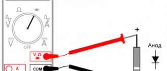
You will need to select the resistance parameters measuring mode on the device. Next, make sure to turn off the circuit breaker that supplies the light. The terminal leads are connected to the tester wires. Now everything is ready to determine the resistance. The value “zero” should be observed in the on position, and when turned off we detect “infinity”. If this condition is not met, the switch will need to be replaced or repaired after dismantling it.
Sometimes a multimeter is not available at the right time, and then a voltmeter will come to the rescue. To determine the operability of the switch, we install it in the position of measuring the mains voltage. “Landing” on the terminal contacts is carried out after turning off the power supply. The direct measurement procedure occurs after turning on the power supply. A prerequisite is the presence of at least one working lamp in the lamp. 220 V indicators should be shown in the off state. In the absence of voltage, it can be argued that the breakdown will be located outside the area of the switch being tested. The disappearance of tension is observed in the opposite state. If there are no such signs, the fault definitely lies in the contacts.
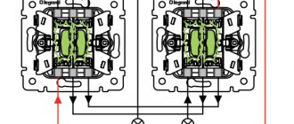
Look at the correct test of a two-gang type switch using a multimeter:
Checking the light switch with a multimeter
When operating the switch, the contacts close and open, so it is most reliable to check the serviceability of the switch with a tester or ohmmeter.
Instead of a tester, you can use a battery and a light bulb.
- 1. turn off the circuit breaker;
- 2. open the cover of the device and, if necessary, remove it from the installation box;
- 3. switch the multimeter to the “resistance measurement” position;
- 4. measure the resistance of the switch in both positions - “on” and “off”.
The readings of the device when taking measurements should be different - “0” or a lit continuity lamp when it’s on and an infinity or unlit lamp when it’s off.
Before checking the switch with a multimeter , you need to use an indicator to make sure that there is no voltage at the terminals.
How to check a switch with an indicator screwdriver
When the key is in the off state, a testing procedure is carried out with a phase indicator on the terminals. The light circuit breaker must be turned on. In such a case, the voltage itself will be on only one of the terminals. If its absence is detected on both terminals, then the conclusion is clear - the problem does not lie in the switch. Next, we turn on the light and use the indicator to test the second connection. Let's consider two ways to break a phase or neutral wire:
- The zero end of the wire is led directly to the lamp, and the other, naturally, at the break. In this case, there is voltage at each terminal in the on position. A violation of such a rule indicates a malfunction.
- Here, the phase is “on duty” on the lamp, and the zero is inserted into the gap. In the on position, there is no voltage on both terminals, and its presence on at least one is a sign of a malfunction of the switch. A very gross error that can cause negative consequences is laying the phase directly to the lamp and breaking the “zero”.
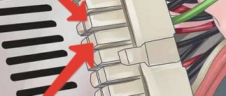
Method 1. We close the contacts on the motherboard
First of all, you need to make sure that the computer does not turn on due to a faulty power button.
To do this, disconnect the contacts of the Power SW from the motherboard connector.
Disconnect the Power SW connector from the motherboard
Then we close the two contacts with a screwdriver or other suitable metal object.
We close two contacts with a metal object - to turn on the computer
If the computer turns on by closing the contacts on the motherboard, but the button does not, then the output means the button is faulty. Check the wires going to the button, maybe one of the wires is disconnected and needs to be soldered.
If, after closing the contacts on the motherboard, the computer does not turn on, then check whether voltage is supplied to the power supply and whether the button on the power supply is turned on.
Checking the power supply
Before making sure that the computer really does not turn on due to a faulty power button, you need to check whether voltage is supplied to the computer.
- Check if there is voltage at the outlet.
- Check the power cable connection.
- Make sure the button on the power supply is in the ON .
The voltage in the outlet can be checked, for example, by connecting a table lamp to the outlet. Is the lamp shining? Okay, let's move on.
Check whether the power cable is securely connected to the power supply connector. Power cables rarely fail, but to be sure, you can try connecting a cable from the monitor to the computer. In most cases they are the same.
Checking the cable connection in the computer power supply
Turn the button on the power supply that was accidentally turned off to the on position.
The button on the power supply must be in the ON position
After making sure that everything is connected as it should, we try to turn on the computer by closing the PW contacts on the motherboard, as shown above. If there is power and the computer still does not start, then most likely the problem is in the power supply.
How to check the power supply for serviceability, read this article -
If this is difficult for you, then write to me in the VK group - https://vk.com/ruslankomp and describe your computer problem.
I will help you solve a problem with your PC or laptop. Join the VK group - ruslankomp
How to test a switch with a light bulb
The control light is screwed into a socket with a pair of insulated wires coming out of it. Stripping the ends of the wires is done by 10 mm. Then the machine designed to power the light is turned on. We touch the switch terminals with the cleaned areas. The light should appear in the off position of the key, but not at full power. This is due to the sequential way our lamp is switched on with other lighting elements. The brightness in this case will be proportional to the ratio of the power of the control element and the total power of all other lamps. The absence of lighting indicates that the switch is working properly. Now we perform the procedure with the light on. If the light is identical to that in the off position, there is a problem with the switch.
Types of switches and operating principles
Three-key switch
Based on the number of switched chains and the number of keys, all existing varieties of these devices are divided into the following types:
- single-key models;
- two-key samples;
- three-key devices.
Another type of old device is still in use, in which the element that controls the switch mechanism is more like a button.
In addition, rare types of rotary-type switching products are presented on the domestic market. In terms of control method, they are a bit like a packet switch. There are also inexpensive Chinese devices related to touch sensitive devices. To control them, you don’t need much effort - just put your finger on the contact plate.
The operating principle of a conventional type switch is based on the closure of the moving and fixed contacts when the key is moved to the upper position and their opening when the reverse action occurs. The so-called “pass-through” switch works in the same way, differing from the usual one in the presence of additional groups of contacts, as well as in the method of inclusion in the lighting network.
Backlit samples
Recently, such models have become very popular. In their design, compact neon-type indicator lamps or LEDs with resistors are mounted in parallel with conventional contacts. Here is a diagram of this option:
Current flows through the LED with current-limiting resistance and the lamp itself in the off position. Its parameters are clearly not enough to light a lamp, but it is quite enough to light an LED. The main purpose of this little trick is to help you find the switch in a dark room. When turned on, the LED is shunted by contacts, it is de-energized and the light disappears.
The presence of such a circuit makes it easy to test the state of the contacts and is very convenient to use. In this case, it is quite appropriate to talk about using the test lamp technique to check serviceability. Let's give an example - if the LED did not stop burning after pressing the key, and the light did not appear, it means that the contacts did not close.
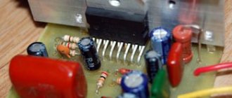
Dimmer
This device will help if you need to adjust the brightness level. The electronic filling of modern samples allows you to set the most suitable parameters. A lamp circuit is integrated into the operation of the regulator, which can block the device if the lighting element burns out. This feature affects the testing of the device in question.
Testing usually begins by disconnecting power from the control device terminals. The loose ends are joined and the machine is turned on. The lighting of the light indicates a breakdown of the regulator.
In some cases the fuse may blow. Checking this element is shown in the video:
Poor contact condition is another common option.
So we have become familiar with the most common methods of checking a switch, which will be useful to you in practice.
Related materials:
- Switch technical characteristics
- Diagram of a two-key switch for two ...
- Scheme: two switches for one...
- Connecting an illuminated switch
← Previous page
Next page →
Causes of dimmer failures
Main reasons for failure:
- Increased load on the device (for example, due to the installation of additional lamps or parallel connection of several lampshades). To prevent damage, it is recommended to select a dimmer with a power reserve of at least 30%.
- Short circuit in the circuit (for example, when a lamp fails or the wire insulation is damaged). Devices designed for increased load are less likely to fail due to short circuits.
- Burnout of the coil when the incandescent lamps are turned on due to a surge in current (the parameter is several times higher than the operating value). Using a dimmer with a power reserve allows you to avoid breakdowns.
- Mechanical damage to the dimmer due to frequent use or excessive loads.
- Peeling of metal tracks on a printed circuit board due to manufacturing defects. Operation in a room with high humidity leads to the appearance of oxides that impair current conductivity.
If the owner of the premises discovers that the dimmer is not working, it is necessary to conduct preliminary testing. The cause of the malfunction is a failed triac or damage to the tracks on the device's printed circuit board.
Some regulators have a fuse that trips when current surges in the circuit and prevents components from burning out. It is necessary to install a new element with a rating corresponding to the original fuse.