It is impossible to imagine a modern home without electricity. Naturally, from time to time there is a need to repair electrical wiring, for which you need the appropriate tools, one of which is an indicator screwdriver.
Using this device, you can determine the presence of voltage, as well as find the phase wire, but this does not work in all situations, and during work, sometimes it becomes necessary to figure out why the indicator screwdriver lights up on all the wires.
Indicator screwdriver design
Devices manufactured in Soviet times had the same design and operating principle. Nowadays, there are several types of such devices. Despite this, if an electrician knows how to find phase and zero with an old design indicator screwdriver, he can easily do this with a more modern tool.
| Important! All indicator screwdrivers are designed for measurements in networks up to 1 kV. |
The simplest tool with a neon light bulb
These are the simplest devices known since the mid-twentieth century. The indicator consists of the following parts:
- Plastic body with a steel blade shaped like a screwdriver. This allows you to use the device not only for phase search, but also as a regular screwdriver.
- Current limiting resistor with a resistance of 1-2 MOhm. Its size not only protects the neon lamp from burning out, but also allows it to close the circuit through the human body.
- Neon indicator light. Its glow indicates the presence of voltage in the conductor being tested.
- Spring. Presses all parts against each other and ensures reliable contact between them.
- Contact plate. May have the shape of a ring or platform. During measurements, you must touch the plate with your bare hand.
The amount of current flowing through the instrument during measurement is very small and cannot be felt by the hands, but it is sufficient for the indicator to glow . The response voltage is determined by the type of lamp and is 60-90V.
Indicator with LED and battery
Neon indicators are being replaced by more modern devices with LEDs and powered by a built-in battery. The rules for taking measurements are similar to screwdrivers with neon, but instead of a resistor and a light bulb, there is a bipolar transistor, a battery and an LED inside.
| Information! Some indicator models allow you not only to determine the phase wire, but also to locate it in the wall at a depth of up to 1.5 mm. |
Smart electronic screwdrivers
In addition to simple devices that show the measurement result by the presence or absence of a glow, there are more complex devices called “mini-multimeters”. These devices show the result on an LCD display or by glowing several LEDs of different colors.
Principle of operation
In new buildings and old buildings, the energy transmission scheme is fundamentally different. The electrical network of new buildings is designed according to the TN-S principle:
- electricity comes from transformers with a secondary winding connected in a star connection (wires converging at the zero point);
- the second part of the ends of the cables is led to terminals A, B, C, also connected at the zero point, and is connected via a ground loop to the substation;
- a high-voltage wire with zero resistance is divided into protective PE (yellow-green) and working N (blue).
In the general switchboard of a new building, 3 phases, a protective conductor and a neutral wire are supplied.
Old buildings do not have protective wiring. The outdated four-wire TN-C system is implemented there:
- the neutral grounded conductor is located in the distribution box;
- phase and neutral from the transformer are connected to the building through underground or above-ground high-voltage cables;
- the wires are connected in the input panel, forming a three-phase system with an operating voltage of 220 or 380 V;
- From the panel, wiring is carried out to apartments and entrances;
- consumers receive electricity from the wires of one of the phases through a network with a voltage of 220 V;
- the difference in load is eliminated by connecting the neutral N-wire.
Electrical wiring diagrams for older homes are outdated and unsafe.
Operating modes
There are the following neutral modes of electrical networks:
- solidly grounded (networks at 380 volts - 110 kilovolts) - the neutral and ground potentials are the same;
- isolated (networks at 6, 10 and 35 kilovolts) – minor current leaks are observed between the neutral and ground;
- part of an electrical network with low resistance impedance and ground resistance.
A neutral wire is used to prevent emergency voltage surges in a phase, for the purpose of relay protection against phase-to-ground faults, as well as to ensure the reliable operation of electrical appliances.
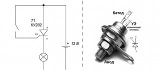
Indicator screwdriver with neon lamp
The operating principle of this device is based on the flow of active current through a neon lamp. When the tip of a screwdriver touches a live wire, current flows through the chain:
- 1. wire;
- 2. screwdriver blade;
- 3. resistor;
- 4. spring;
- 5. neon lamp;
- 6. contact plate;
- 7. human body;
- 8. floor;
- 9. foundation;
- 10. soil.
The current strength is no more than 0.2 mA, which is absolutely safe for health and imperceptible to the human body and hands.
Two phases in all sockets
If the lights in the entire house are turned off, and the voltage indicator shows two phases in the sockets, the problem is most likely on the input panel.
In this case, you must also check the ground wires in case they are grounded. At the same time, until you are sure that there is no voltage on them, you should not touch the grounding contacts with your bare hands and prohibit children from touching sockets and electrical appliances.
In old houses, plugs or circuit breakers are often installed not only on the phase, as recommended by the latest editions of the PUE, but also on the neutral wire. The burnout of such a plug is equivalent to a break in the zero, so it is recommended to check them first.
It is also necessary to take into account the possibility of the absence of an electrical panel as such, when the wire from the meter goes directly to the main distribution box - the faulty contact may be in it.
If everything is in order in the apartment, then the neutral wire on the floor distribution panel is checked - it is likely that an electrician from the housing office will have to be invited for this.
Indicator screwdriver with LED
This is a more modern tool that allows you to take measurements without touching the contact plate. During measurements, the weak current flowing through the screwdriver is amplified by an electronic circuit consisting of a bipolar transistor and a battery. This is enough to light up the LED.
The presence of an LED and a battery allows you to check the integrity of the wire section. To do this, you need to touch the end of the disconnected wire with the tip of a screwdriver. In this case, you need to touch the contact plate with one hand, and with the other hand you need to touch the other end of the wire.
| Information! If you take the tip of a screwdriver in your hand and run the handle along the surface of the wall, the glow of the indicator will indicate the presence of a phase wire under the layer of plaster. |
Break of zero at the input
If the zero wire in the incoming cable is disconnected, the lights in the apartment will go out and electrical appliances will stop. Checking with an indicator will show the presence of a phase on each contact of the socket. The classic question arises: “Who is to blame and what to do?”
In the absence of zero, the current searches for a free line. If the lamp is turned on, it does not light, but the phase passes through the filament to the neutral wire, then to the bus, and from there to the neutral line of sockets. The phase can also come from a device connected to any plug connector in the apartment. Now there is a phase on each socket of the socket. The indicator emits a light signal when each contact is touched.
A multimeter helps to easily clarify the situation. If you measure the voltage difference between two phases, the device will show a zero value. It is clear that this is the same phase. It is enough to turn off the lamps and disconnect the devices from the sockets and the second phase in the socket will disappear, because the voltage and neutral supply lines do not have other connection points.
It is necessary to restore the incoming zero line. It is possible that the wire has simply become disconnected from the bus. This problem can be dealt with even at home. De-energize the apartment by opening the phase input and check the absence of voltage. Insert the neutral lead into the terminal and tighten the screw.
Why does the indicator show phase on both wires?
Electricians make a conclusion about the presence of voltage on the wires by the glow of a neon light bulb or LED, but this does not always indicate the presence of phase on both contacts, so in fact the question should be posed as follows - why does the indicator screwdriver light up on all wires.
There are several reasons for this phenomenon:
- Induced voltage or “crosstalk”. In modern buildings there is a fairly high level of electromagnetic fields and in wires not connected to electrical appliances, these fields induce alternating voltage. If the cables are long or located near other wires, the magnitude of this voltage may be sufficient to cause the indicator to light.
- Poor insulation. The reason why the indicator lights up on the neutral wire may be poor insulation between the neutral and phase wires. In this case, the phase conductor may belong to a completely different line. In this case, if the neutral is broken, the indicator screwdriver will show the phase in the foreign cable through the neutral conductor.
- Zero break. In this case, the glow of the indicator occurs due to the large length of the wire or a phase in this conductor may appear through an electrical appliance connected to the network, for example, a light bulb.
- The presence of a different phase in the neutral conductor. This malfunction can only be determined with a tester, voltmeter or other device that is connected to both wires at the same time and shows the voltage value. The indicator screwdriver will only indicate the presence of phases on both wires.
Induced currents
Everything works fine, but the indicator detects voltage on each pin of the plug connector. Moreover: the device shows two phases in the socket when the power supply to the entire apartment is turned off. This completely unrealistic situation can happen if a high-voltage power line runs near your home.
The information posted on this page is for informational purposes only. We recommend that all electrical work be carried out by a professional electrician.
This is the so-called pickup or, to put it more correctly, induced voltage. Even experienced electricians can get confused here. Work in this case is associated with a high risk of electric shock, so only professionals should perform it.
Reasons for the appearance of two phases
The reason that the indicator screwdriver shows two phases may actually be the presence of two phases. This happens due to various electrical wiring faults.
Broken neutral in the power line or input panel
The reason why the indicator screwdriver lights up on all wires may be a break in the neutral wire. This is due to the fact that modern three-phase 0.4 kV networks are connected to the ground loop using the TN system and 4 wires are laid to consumers - 3 phase and 1 neutral.
Due to the fact that the load is unevenly distributed across the phases, an equalizing current flows along the neutral conductor. Due to this, the voltage between the neutral and phase conductors is the same in all phases.
When the connection between the neutral wire and the neutral of the transformer breaks, the equality is violated, the voltage between the phase and neutral wires in less loaded phases increases and a voltage appears between the neutral wire and the ground, the value of which can reach 100-200V, which is enough for the indicator to glow.
High resistance in the neutral conductor
All wires have resistance to electric current, therefore, when calculating a power line, not only the permissible heating is taken into account, but also the voltage drop, including in the neutral conductor.
An additional contribution to the fall is made by poor contacts at the junctions of the wires.
If the load on the electrical network corresponds to the nominal value, the voltage on this wire between the transformer neutral and the consumer is no more than 23V, but as the load increases and its uneven distribution, the current and losses increase, which causes a voltage imbalance similar to a neutral break.
Short circuit
The second phase may appear in the socket due to a short circuit between the neutral and phase conductors. If proper protection is installed, an emergency shutdown of a section of the network will occur.
In addition, the connection in the neutral wire between the point of closure and the transformer may burn out. In this case, several scenarios are possible in which the screwdriver shows the phase on both wires:
- Both contacts in consumer sockets connected to the closed phase will have the same phase. The voltage between them will be “0” .
- At the contacts of consumer sockets connected to other phases, the voltage will be 380 (400) V instead of 220 (230) V.
| Important! The presence of two DIFFERENT phases in the socket and, as a result, increased voltage, is an emergency and can lead to failure of electrical appliances connected to the network. |
Voltage between phase and neutral and ground conductors
The voltage between the phase and the neutral and grounding conductors can also be different:
- Near the transformer substation it is the same. Due to the absence of voltage drop in the wires, it is equal to the output voltage of the transformer;
- At a considerable distance from the substation, the difference in voltage between the phase and the neutral and grounding conductors is determined by the voltage drop in the neutral wire. Therefore, the potential difference between phase and neutral can be either greater or less than between phase and ground.
- If the neutral is broken, the voltage between phase and ground is 220V, and between the phase wire and neutral can reach 380V. This can lead to failure of all electrical appliances connected to the network.
| Advice! To protect household appliances from overvoltage, it is advisable to install a LV voltage relay immediately after the input circuit breaker. |
Indicator screwdriver lights up on ground
The reason that the indicator shows the phase on the ground is most often its absence. When installing electrical wiring, a grounding conductor is laid and connected to sockets and the electrical panel, but the panel itself is not connected to the grounding loop.
It is also possible that the circuit itself is broken or is in dry soil. In this case, the screwdriver shows the induced voltage.
Another reason for this phenomenon may be a short circuit between the phase wire and grounded structural elements or a grounding wire, followed by burnout of the conductor connecting the shield to the circuit parts located in the ground.
In which socket should the phase in the socket be?
Many people will find this question funny. But, nevertheless, due certainty should be immediately introduced with this, since the publication is intended for completely inexperienced users. And they, no, no, and there are some ambiguities. This probably explains a considerable number of search queries like “in which hole in the socket should I look for the phase”? (It would probably be more correct to say “in which nest”).
So, we look at a single-phase socket of those standards that can be found in Russian homes - most often it is type C or type F.
Differences in standard C (left) and F (right) sockets. The only difference is the presence of a grounding contact.
Type C is the most common socket with two sockets for the contact pins of the plug. One socket must have a phase contact ( L ), and the second one must have a neutral contact ( N ). And no more embellishments.
Type F has recently been increasingly replacing type C. This is due to the fact that in urban new buildings the electrical wiring system began to be initially planned with the presence of a PE . It is becoming the norm to install reliable grounding in private homes. This is due to the requirements for ensuring the safe operation of household electrical appliances. Take a look at the power plugs of your home appliances - in the vast majority of cases, modern devices “ask” for connection to a ground loop. Therefore, standard F sockets provide an additional contact specifically for these purposes. It consists of two shaped spring-loaded plates located exactly in the center of the socket at the top and bottom.
But no matter what the socket is, there must definitely be a phase and a neutral in its sockets. No other options are provided. The presence of a grounding contact does not change this rule in any way.
For single-phase household appliances operating from a 220 V network, the relative position of phase and zero in the vast majority of cases does not matter at all. And during operation, owners often insert a plug into a socket without thinking at all about its spatial position - in short, how it turns out. And this does not have any effect on the performance of the equipment.
Note that there are exceptions in this regard. Some devices, such as air conditioning or heating systems with built-in thermostatic controls, require a unique phase and neutral location on their terminal block. But, as a rule, these devices are permanently installed and are connected not through sockets, but directly to dedicated wiring lines connected to them.
On this thermostat for electric heated floors, the position of phase and zero is strictly specified.
But such devices are usually installed and connected according to a stationary circuit, and not through sockets. So which socket should you look for the phase when checking sockets?
The answer is categorical - you should always check both sockets. There is no need to rely on supposedly existing standards for the location of contacts. And first of all, because such standards do not exist at all.
What they say about the correct phase position in the right socket is not fixed by anyone or anywhere. Yes, many master electricians of the “old school” observe the “polarity” of sockets, actually connecting the phase to the right terminal when looking at the socket from the front. But this, rather, can be considered a kind of “rule of good manners” that distinguishes specialists with a professional approach.
The diagram shows that the phase contact on the sockets is located on the right. But this is not a rigid standard, but simply an unspoken rule, a kind of “professional ethics” of electricians.
It is clear that with an orderly arrangement of phase and zero, it is easier to deal with faults and diagnose the home electrical network. Moreover, there are special devices that allow you to very quickly and accurately diagnose the outlet line - the presence of breaks or leaks, the correct connection of contacts, etc. This tester just needs to be plugged into a power outlet and turned on.
A special diagnostic device MS6860D, designed specifically for testing sockets and wiring lines suitable for them
So, the layout of such devices is designed specifically for the right-hand location of the phase socket. That is, when the tester is plugged into the socket correctly, all the inscriptions are readable. The illustration above shows an example of such a device, and the phase LED is highlighted with an arrow - it is located on the right. Of course, nothing prevents you from turning on the tester “upside down” - it will cope with the task perfectly even in the case when the phase is on the left. But, nevertheless, it is precisely this “correct” layout that still says something...
But, again, don’t blindly rely on these unspoken rules. In any case, when checking the phase, both sockets should be checked.
How to determine where the phase is and where the zero is in a socket?
Any owner of a house or apartment will probably have to deal with such a “diagnostic operation”. The test is carried out using inexpensive instruments, which you should definitely have in your tool arsenal. How to determine phase and zero - read in a special publication on our portal.
And while checking both nests, if the “light” goes out, the owner may be in for a very unexpected and rather unpleasant “surprise”. This is exactly what will be discussed further.
Selecting settings for TZNP
To ensure the stepwise principle of line output, the current protection that controls the appearance of a zero sequence in the circuits must correspond to the selectivity of operation. Here, selectivity refers to the sequential switching off of certain sections of the circuit, depending on their significance, in order to determine the location of the damage or highlight the damaged gap. To do this, select the appropriate time settings for protection. Consider an example of setting settings in this diagram.
Setting selection example
As you can see, in this case the TZNP is configured according to the same principle as the maximum current protection, but with a shorter time delay. In this example, each subsequent protection stage withstands a time delay for an interval Δt greater than the previous one. That is, the response time of the first current cutoff, in comparison with the second, will be calculated according to the formula: t1 = t2+ Δt. And the response time of the second in relation to the third will be t2 = t3+ Δt. Thus, each subsequent relay performs the function of backup protection.
If the windings of the converter devices are connected according to the star-delta system, as well as the star-star system, the TZNP of the primary and secondary circuits do not match. Due to the fact that a short circuit in high voltage lines will not necessarily cause the appearance of zero sequence components in the low windings and the circuit fed by them. Since the TZNP selectivity for each of them must be built independently, in practice their independent operation must be ensured.
This system of stepwise protection allows minimizing the further transfer of damage to other sections of the network and power equipment. It also helps to remove the personnel servicing these devices from danger. The main requirement for current protection is the prevention of false switching in relation to the corresponding trigger zone.