Signal inversion circuits can be used to invert door or trunk switch signals when connecting to an alarm system or in other cases. As soon as you start the engine, the oil pressure warning light on the dashboard goes out, a signal from the oil pressure sensor arrives at relay contact 86, this signal excites the coil in the relay, which controls the closure of contacts 30 and How to open the trunk from the alarm key fob? Contact copper plastic and a flexible wire can be placed on the armature, then the armature is energized and voltage is supplied to the fixed contact through the copper busbars. When fastening parts melt, the contacts shift and a sparking process is added, which further heats the contact point. How a 5-pin relay works and works
Electronic relays A conventional electromagnetic relay clicks when activated, which can interfere with your use of such devices in domestic premises. Advantages of the relay: simplicity of design; maintainability. I started looking for different ways to make money on the Internet. These elements are used to protect control circuits from overloads that occur when the relay coil circuit opens. Let's talk a little about the operating principle of a 5-pin relay. A brief overview of domestic standard relays in housings as shown in the photograph below.
Now let's briefly go over the rules for the operation and use of DRLs: DRLs should be used only during daylight hours; It is prohibited to use DRLs in conjunction with side lights, low and high beam headlights, as well as fog lights. When working, you should take into account the type of contacts, the type of device and the principle of its operation.
How to connect daytime running lights (DRL) using a relay
Information business website
The general meaning of connecting via a relay is the load on the switch that controls the installed equipment. At rest, i.e. And the more parts, the less reliability. In: Business secrets Knowing how a relay works, you can implement various connection schemes to the car's electrical wiring. Connection diagram for central locking with an additionally installed activator and activators for alarms that do not have built-in central locking interface relays. Contacts 30 and 86 are swapped. Namely. The contacts provide control of the electrical circuit, opening and closing it. You have no way to turn off the DRLs until you remove the key from the ignition. Voltage is connected to the coil, the magnetic field attracts the armature, it closes or opens the contacts. Download here. Pulse relay operating principle and connection diagram. Part 2
Read additionally: Insulation readings do not meet the regulatory requirements
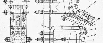
Signal connection diagram via 4-pin relay
In my opinion, everything is already clear, and they have already written about this many times, but it may be useful to someone. For example, I recently gave a car I had made to a man, and over time his signal stopped working. You can’t travel all over Moscow for trifles, so he asked me to draw a diagram for him, I did it, but don’t disappear. I decided to post it publicly.
Description, I will try to use simple understandable language:
Two opposite contacts on the relay, numbered No. 86 and 85, are the so-called control contacts. If voltage is applied to them, the relay will close, and then direct voltage will flow through contacts No. 30-No. 87. Well, let’s say a contact that you need to break and briefly close, let’s say a signal. Why through a relay? Well, let’s take the interior button for example, the contacts on the buttons are weak and are not designed for direct load, and if you apply the plus from the battery through the button, say, to the starter, then after the first use the button will melt. Therefore, through the interior button we connect the control wires to the relay, and the direct plus to the consumer, in our case the signal. Thus, through a relay from the battery to the input (contact No. 87) and output (contact No. 30) to the consumer (Signal).
What is a control minus? Usually, on the relay, the minus goes directly to contact No. 86, and the control plus is opened with a key (button). In our case, the key (button) already exists, this is the signal button on the steering wheel. The way it is designed, the steering shaft is connected to the steering column and body through rolling bearings, and there is always a constant minus on it. Next, the minus from the steering shaft is fed to the core of the steering wheel, a contactor is installed in the steering wheel itself, to which the minus from the steering wheel fits on one side, and on the other side the contact goes to a contact round plate (most often copper or brass) along which on the steering side the stationary contact slides on the shaft, it then removes the minus from the steering wheel button and sends it further to the signal, in our case to the relay, to contact No. 86. So, not everything is so complicated and shrouded in mystery; if you have never dealt with electrics, then don’t go into details, just connect according to the diagram, which in my opinion is quite simple. I hope my article will help someone.
It is often difficult for novice auto electricians and people modifying their car to understand the phrase “connect via a relay.” What does connecting via a relay mean and how to do it? Let's figure it out.
Before studying the wiring diagram for any automotive device via a relay, you need to know what a relay is in general and how it works. This is written about in detail here
.
Once you understand the operating principle of this simple device, it will be much easier to figure out how to connect it. Read more: Chevrolet Lacetti timing belt kit 1 4
The general meaning of connecting via a relay is the load on the switch that controls the equipment being installed. All powerful consumers of electricity in the car (for example, headlights, starter, fuel pump, heated rear window, electric power steering) are connected through a relay. Thanks to this, these devices can be controlled by small, beautiful buttons instead of rough and large switches. In addition, in some cases, the relay allows you to save on wires.
The relay is connected to an open circuit in the electrical circuit. Let's look at installing a relay using the example of a gas pump. Power is supplied to it by the engine control unit (hereinafter referred to as the computer) and in order for the computer board tracks to withstand the current consumed by the pump, they would have to be made too powerful. Passing strong current near sensitive electronic components of a computer can affect their operation. To avoid such problems, a relay is installed between the computer and the fuel pump and the computer is connected not to the pump, but to this little “helper”.
The relay, as it were, divides the wire going from the fuse block to the pump into two parts, which can close inside the relay when voltage is applied to the control contacts of the magnet. As already mentioned in the article about the relay device, the control current is very small and cannot damage the computer in any way. The computer supplies voltage to the control contacts of the relay, and it then “connects” the power circuit within itself and connects the fuel pump.
Using the same principle, the relay is installed on any other electrical consumers in the car. Let's consider connecting fog lights.
The wires to the fog lights come from the fuse box, but they go through a relay along the way. The process of turning the headlights on/off is controlled by a button on the dashboard. When it is pressed, voltage is supplied to one of the control contacts of the relay, and it closes the power circuit - the lamps in the headlights light up. The second control contact of the relay is “mass”, that is, voltage goes through it to the car body, creating an electrical circuit.
Using this circuit, you can connect almost any powerful device and control it with a small, beautiful key. In some cases, a relay can be a salvation from factory defects. For example, in a VAZ-2106, the current flowing to the starter solenoid relay through the ignition switch quickly leads to a malfunction of the lock contact group
. They get rid of this trouble by installing an intermediate relay and changing the power supply of the solenoid relay. After modification, a weak control current begins to pass through the contact group of the lock, and the relay connects powerful power to the starter.
Sound signal GAZ in NIVU
Lately there have been a lot of inappropriate behavior on the roads. Few people pay attention to the native quiet signal. Therefore, I decided to install a signal from GAZ. I bought the following signals produced by LETZ without brackets:
I decided to put it behind the radiator grille, because... Under the hood the sound would still be a little muffled. Standard signal:
Read more: Antifreeze psa longlife 9735 k0
To place the signals, I made the following mounts from stainless steel:
Connection diagram via relay:
True, I took the power from fuse No. 15 which is 16A
The power wires go into the factory hole:
The relay is located on the brake fluid reservoir mounting stud:
The original “+” and “-” wires were not enough to reach the relay; we had to extend them by about 25 cm. In order for the signals to fit in, we need to file down the “pipes” a little with sandpaper. Next, everything is painted, moviled and assembled:
Signals don't come out
Installing a sound signal from GAZ (PAZ) in NIVU
Another day of vacation was marked by an improvement in the sound signal of my car. I was very depressed by the sound of the stock signal; it seemed like a solid car, but it beeped like a castrated hedgehog. Well, somehow it’s not solid. Ideally, these are pneumatic pipes, but while there is no pneumatic system, I bought two sound signals from GAZ (PAZ), one high, the other low. Their sound pressure level is 105-118 dB.
To begin with, I was looking for a place to stick them, they were too big. I planned to do it from the front, instead of the standard one, but I couldn’t unscrew the grille mounting bolts.
I opened the hood and began to think about where I could stick the new horns. And then I saw the spare tire fastener, which had not been used for its intended purpose for a long time... In which I drilled two holes with an 8mm metal drill:
Knowing the ability of a minus to disappear somewhere, due to dirt or loosening of fasteners, I protected myself a little and brought out an additional minus:
Then I secured it all and began to think about how to connect the power relay. I'm a complete novice when it comes to electricians, so a call to an electrician friend provided me with this “sacred” knowledge. And after a little prayer to all the Electrical Gods, I began to connect the wires to the relay. Everything turned out perfect. The signal worked in such a way that my ears remembered this sound for a long time...
That's all. Everything works, everything beeps. Now the sound produced is similar to the roar of a rhinoceros during the “rut”.
Diagram for connecting new signals to standard wiring
sound signal via power relay:
Repair of NIVA sound signal
The sliding contact of the horn broke off.
Well, off we go. - take the socket from the rear light 05 (only the terminal from it) - screw - drill + 2mm drill
We knock the rivet off the standard terminal
Let's drill a hole. We take a new contact, a screw and a nut, because the screw is too long
Along the way, I decided to put a button on the signal, parallel to the steering wheel, for convenience. Press with your left hand.
Replacing the standard Niva sound signal with a C308/309
I decided to install the purchased C308/309 kit (VAZ-2103/06 until 1993) in a similar way.
The sockets are tilted down so as not to collect moisture; to do this, we had to disassemble the signals and turn the top covers 90′, otherwise you won’t be able to get to the terminals later
I really hoped that the signal housings were smaller and that I wouldn’t have to cut anything. I had to. The lining did not want to be put on, and since I didn’t have a hacksaw blade with me, I bent the excess metal on the bell of the lower signal.
Read more: VAZ tire pressure table
I took the following connection diagram:
Wire - 1.5 sq. mm. I connected the power to the standard signal circuit, there is a 16A fuse there, in addition to the signal from this fuse, the rear brake lights and interior lamps are powered (I have all of these on LEDs).
I attached the relay under the spare tire bracket. Not the best place, but most of the time it's dry
Connection diagram for a signal from the Volga via a 4-pin relay, for cars with a control minus on the steering wheel button
In my opinion, everything is clear, and they have already written about this many times, but it may be useful to someone. For example, I recently gave a car I had made to a man, and over time his signal stopped working. You can’t travel all over Moscow for trifles, so he asked me to draw a diagram for him, I did it, but don’t disappear. I decided to post it publicly.
Description, I will try to use simple understandable language:
Two opposite contacts on the relay, numbered No. 86 and 85, are the so-called control contacts. If voltage is applied to them, the relay will close, and then direct voltage will flow through contacts No. 30-No. 87. Well, let's say a contact that you need to break and short-circuit, let's say a signal. Why through a relay? Well, let’s take the interior button for example, the contacts on the buttons are weak and are not designed for direct load, and if you apply the plus from the battery through the button, say, to the starter, then after the first use the button will melt. Therefore, through the interior button we connect the control wires to the relay, and the direct plus to the consumer, in our case the signal. Thus, through a relay from the battery to the input (contact No. 87) and output (contact No. 30) to the consumer (Signal).
What is a control minus? Usually, on the relay, the minus goes directly to contact No. 86, and the control plus is opened with a key (button). In our case, the key (button) already exists, this is the signal button on the steering wheel. The way it is designed, the steering shaft is connected to the steering column and body through rolling bearings, and there is always a constant minus on it. Next, the minus from the steering shaft is fed to the core of the steering wheel, a contactor is installed in the steering wheel itself, to which the minus from the steering wheel fits on one side, and on the other side the contact goes to a contact round plate (most often copper or brass) along which on the steering side the stationary contact slides on the shaft, it then removes the minus from the steering wheel button and sends it further to the signal, in our case to the relay, to contact No. 86. So, not everything is so complicated and shrouded in mystery; if you have never dealt with electrics, then don’t go into details, just connect according to the diagram, which in my opinion is quite simple.
https://www.drive2.ru/l/7167688/, https://www.drive2.ru/l/4267252/, https://www.drive2.ru/l/288230376152851567/, https://www .drive2.ru/l/6903680/, https://www.drive2.ru/l/5129987/
Generator NIVA
Bracket for transferring the VAZ-2121 generator for NIVA Transfer of the KZATE 80A generator (step by step
Stories from our readers
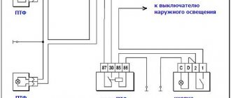
Separately, I would like to dwell on an important point, it concerns the use of DRLs in conjunction with high beam headlights. Without supplying voltage to the winding contacts, it is permanently closed to contact 87a. The contact parameters and the maximum switching current are also indicated under the electrical diagram. But I don’t want to strain the wiring through the relay.
The drive will operate and the trunk will open. I started looking for different ways to make money on the Internet. Voltage is connected to the coil, the magnetic field attracts the armature, it closes or opens the contacts. This will be considered as making changes to the design of the vehicle. With this connection, either the DRLs or the headlights may work.
Usually a relay has 5 contacts, there are 4-pin and 7-pin, etc. Legislation Before practicing installing DRLs, I would like to dwell a little on the legal standards for installing DRLs, as well as the rules of their operation. Coil actuation voltage.
5 pin relay diagram
Pins 85 and 86 are the coil. For a three-phase network, the following is done: The connection cable is determined - copper, with a cross-section of 1.5 mm2. Let's talk a little about the operating principle of a 5-pin relay. The polarity is inverted.
The relay comes to the rescue again. The phase is located along the markers A, B, C and the zero terminal N. Knowing how the relay works, you can implement various connection schemes to the car's electrical wiring. Now I earn thousands. To control the blocking relay, you can use a secret button, a reed switch-magnet pair, or a standard control element that issues a control signal of positive polarity when the ignition is on, for example, a power signal on the window lifter or heated rear window.
For more automation, take power from the car's main circuit, which turns on when the ignition is turned on; We connect DRLs to contact 87A, which will always be on; We connect the headlights to pin 87, which will turn on only when the DRLs are turned off; It doesn’t matter to contacts 85 or 86, we send a control signal from the headlight button in the cabin; We connect the remaining contact 85 or 86 to the car body. Typically, a relay has 5 contacts; there are also 4-pin and 7-pin, etc. Once you understand the principle of operation of this simple device, it will be much easier to figure out how to connect it. Release voltage: 1, I also advise you to download the application to your phone, it is much more convenient to work from your phone. How to connect the central locking in a car.
Relays, resistors and diodes for cars, description...
A relay is an electromagnetic switch consisting of a coil (contacts 85 and 86), one common contact (30), one normally open (87) and one normally closed (87a) contacts. Such relays are the most common and are called single-pole, two-way relays. When there is no voltage on the coil of such a relay, contacts 30 and 87a are common and
normally closed - connected.
If you apply voltage to the coil, the relay will switch and now contacts 30 and 87 will be closed - common and normally open. If the voltage on the coil now disappears, the relay will return to its original state. When connecting a relay, the polarity of the coil does not matter unless there is a protective diode connecting the coil contacts. If it is not there, you can connect the positive voltage wire (positive) to any of the coil contacts, and the negative wire to the remaining one, otherwise you need to connect the positive wire to the contact to which the cathode of the diode is connected (it is marked with a stripe on its body ), and the negative voltage wire (negative) to its anode. Diodes are most often used to protect relays from overloads that occur when the coil circuit opens. If there is a diode, the coil current flows freely through it, preventing voltage peaks from occurring at the moment of opening and thus protecting the contacts from sparking and other sensitive circuits from these shocks. Why use a relay? Every time you need to connect a device that consumes more current than the control device is capable of delivering to its output, a relay is required. To activate the relay coil, it requires very low currents (no more than 200 milliaperes), and the current passing through the common normally closed and normally open contacts, on the contrary, can be very large and reach 30-40 amperes. This property of the relay allows you to control devices such as headlights, parking lights, horns, etc. using low-current outputs of alarms, central locks or other systems. In some cases, it is necessary to simultaneously turn on several devices using one output. Then this output is connected to multiple relays, which in turn simultaneously close and open multiple circuits at the same time. There are a huge variety of tasks that require the use of relays; below we will consider only the simplest of them as an example. Changing the polarity from negative to positive If you have a negative output on a device such as an alarm or central locking, and you want to use it to control a device that requires +12 volts to operate (for example, headlights or a sunroof lock) you You will need to connect a relay as shown below to change the polarity of the control voltage.
Changing Polarity from Positive to Negative If you instead need to use a positive alarm output with a device that requires a ground connection, connect the relay as follows to change the polarity of the control signal to negative.
Changing Polarity from Positive to Negative If you instead need to use a positive alarm output with a device that requires a ground connection, connect the relay as follows to change the polarity of the control signal to negative.
Resistors Resistors , as well as relays and diodes, are components that are often used in the work of an installer. Most often, they are used in door locking circuits, delay circuits, remote start, or for capacitor discharge. A resistor is a device that creates some specified resistance to the flow of electric current. The greater the resistance, the less current can flow. The main characteristic of a resistor is its resistance, measured in Ohms. Resistance is usually coded with colored stripes on the housing. If 4 bars are used, then the first two encode the denomination, the third - the multiplier and the fourth - the error, if 5 bars are used, then the first 3 of them set the denomination. Let's assume that we have a regular resistor of 1 KOhm and 5% tolerance. To find out its denomination, we need to take the number corresponding to the color of the first strip (in this case it is brown) - this is 1. Then take the number corresponding to the color of the second strip (black) - this is 0. We get the value 10, which must be multiplied by the corresponding multiplier value a color has 3 stripes (red) - this is 100. Thus, we get 10 * 100 = 1000 Ohm = 1 kOhm.
Because Resistors are difficult to manufacture in strict accordance with the nominal value; manufacturers mark resistors with an error bar. It is usually gold or silver, although sometimes it may be absent. Gold color means that the error of the denomination value is a maximum of 5%, silver - 10%, and the absence of an error bar means that the error is 20%. Accuracy means a range of possible values, for example our 1kOhm resistor has a golden error bar (5%) - this means that its actual value lies in the range from 950 ohms to 1050 ohms. If there is no color code on the resistor body, then its value can be indicated on the body (in most domestic models). If there is no code or value on the case, then all that remains is to use a multimeter to measure the nominal value. Resistor color coding table Color 1st stripe 2nd stripe 3rd stripe* Multiplier Accuracy ± % Black 0 0 0 1 Brown1 1 1 10 ± 1% Red 2 2 2 100 ± 2% Orange 3 3 3 1000 Yellow 4 4 4 10,000
Green 5 5 5 100,000 ± 0.5%
Blue 6 6 6 1,000,000 ± 0.25% Purple 7 7 7 10,000,000 ± 0.10% Gray 8 8 8 100,000,000 ± 0.05% White 9 9 9 1,000,000,000 Gold 0.1 ± 5% Silver 0.01 ± 1 0% None ± 20% * If the resistor is marked with 5 stripes, then the value before using the multiplier will be 3-digit and the third digit must be taken from the third column of the table. If only 4 strips are used, then simply ignore this column.
Diodes and everything about them:
You should definitely start studying the installation business with the basics of electronics and electrical engineering. Using just a relay and a few diodes you can create a remote start circuit using an already installed alarm or central locking system. By adding a capacitor and resistor to this you get a timer that will create the necessary delay. Or by adding a relay to one of the remote-controlled outputs of your alarm system, you can turn on several devices at once - for example, an amplifier, headlights, etc. Using Ohm's Law, it is easy to calculate the correct fuse rating in a circuit, or calculate the impedance of a multiple speaker load on an amplifier, and much more. Diodes The easiest to use and one of the most commonly used components are diodes. A diode is a semiconductor device that allows current to flow in only one direction. The diode has two terminals - the anode and the cathode (the cathode is marked with a stripe). Current flows through the diode only when the potential at the anode is greater than at the cathode. How can diodes be used? Here's an example: many cars have two separate door limit switches (triggers) that are installed in isolation from each other (this is usually the case on American cars), one switch for the driver's door, and the second for all the others. If the car alarm unit has only one input for connecting door limit switches, then you need to connect both switches to this input, because if you do not connect at least one of them to the alarm, then part of the car doors will not be protected. On the other hand, if you simply connect both switches to the corresponding input of the alarm unit, then some useful functions, such as the audible door alarm or door open indicators on the dashboard, may disappear or provide incorrect information (for example, incorrectly display which door has opened, one of the passenger or driver's). To isolate two or more positive door limit switches, simply connect them through diodes, so that the anode of each diode is connected to the corresponding trigger, and the cathodes of all diodes are connected to the positive input of the alarm unit.
Using the same scheme, you can connect several sensors with negative outputs, for example, several shock sensors to one alarm input. Typically, unless otherwise stated, the diodes used are assumed to be rated for a maximum current of 1 amp. Current is what flows through a conductor. Current always flows from a point with the highest potential to a point with the lowest potential along the surface of a conductor. Current is symbolized as I, and current is measured in amperes (amps). Voltage is the difference in electrical potential between two points in an electrical circuit. It can be thought of as pressure that allows current to flow. Voltage is denoted by U and is measured in volts (V). Resistance determines how much current can flow through any component. Resistors are used to limit current and voltage levels. High resistance determines that the current will decrease to small values; low resistance, on the contrary, allows currents of large values to flow. Resistance is denoted R and measured in ohms (ohms).
Power determines the rate at which electrical energy is transmitted or converted. It is denoted by P and measured in watts (W). Power is equal to the product of current and voltage. Ohm's law defines the relationship between voltage and current. It states that the strength of direct electric current I in a conductor is directly proportional to the potential difference (voltage) U between two fixed points of this conductor. The proportionality factor is called resistance and is measured in ohms. One ohm is the resistance of a conductor, between the ends of which a voltage of 1 volt occurs at a current of 1 ampere. The diagram shows the relationships between these four quantities, following from Ohm's law.
Principle of operation
Contact 30 is a common contact, contact 87A is a normally closed contact, contact 87 is a normally open contact.
Wiring diagram for a five-pin relay The wiring diagram for a five-pin relay is suitable for creating an alarm. Each contact has its own designation.
This seems complicated, but let's look at an example and everything will become clear.
Signal inversion circuits can be used to invert door or trunk switch signals when connecting to an alarm system or in other cases. We connect to low-current transistor alarm outputs.
Related article: At what depth are electrical cables laid?
Site search
After applying a control signal to the relay, the first output will become open and the second will become closed. As a result, on pin 30 we have the polarity that is on pin
Before studying the wiring diagram for any automotive device via a relay, you need to know what a relay is in general and how it works. Let's consider connecting fog lights. I want to power it up like the DRLs, that is, when I start them they light up, when I turn them off they don’t light up. If we briefly describe this figure, we get the following: DRLs should be installed at a height of to mm; The distance between adjacent edges of the DRLs must be at least mm; The distance from the outer side surface of the car to the nearby edge of the DRL should be no more than mm. After the voltage supply is stopped, the winding current disappears and the core is demagnetized.
Relay Mechanisms
Now, if you try to start the car with the security switched on, contact 30 will open with contact 87A and will not allow the engine to start. Stories from our readers “Fucking basin!!! Signal inversion circuits can be used to invert door or trunk switch signals when connecting to an alarm system or in other cases. Knowing the legislation and rules for using DRLs, we are ready to move on to the practice of connecting them. For a voltage relay Schematic diagram of a home network using voltage relays, RCDs and circuit breakers. The connection diagram for a voltage relay involves mounting the device on a DIN rail in the switchboard.
Let's cut this wire. Imported relays under the Saturn and San Hold brands have proven themselves to be the most reliable and commercially available; relays from other manufacturers are also used. Maximum current in the power circuit: 30A. Structurally, the standard regulator has the form of a bag for mounting on a DIN rail. To connect according to this scheme, you will need a 4-pin relay. RELAY. Easy connection
Scheme options
Schematic diagram of VSO connection on VAZ 2108, 2109, 21099 (until 1998).
As we can see, the sensor controls the fan relay, which is located in the fuse box. When a certain temperature is reached, the contacts of the temperature switch close, which leads to the flow of current in the electric motor circuit.
Above is a diagram for VAZ 2108, 2109, 21099 cars, but after 1998. As we can see, the power sensor now functions as a relay.
Let's consider a circuit using a resistor to implement two propeller rotation speeds using the VW Passat as an example. The two-position fan power sensor S23, depending on the coolant temperature, closes the contacts directly or through an additional resistance.