Purpose and where to use
The use of disconnectors in the energy sector to break circuits is dictated, first of all, by safety considerations. They are used to make connections to contact networks for supplying current from supply lines. These mechanisms also serve to safely change the interconnection patterns of circuit sections.
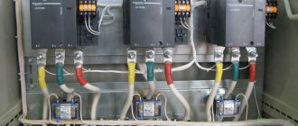
Figure 1 shows a section of a line with high-voltage disconnecting devices.
Figure 1. Line section with high-voltage disconnectors
The switching mechanisms under consideration have two important qualities that allow you to control the switching process:
- The ability to visually monitor the position of moving contacts at disconnection points.
- The absence of a mechanism allowing the possibility of free (arbitrary) release. The use of manual drives ensures that the specialist performs the planned operation of de-energizing or connecting the electrical network at the right time.
This design of the disconnector allows maintenance personnel to quickly assess the condition of the working parts of the switching mechanism before switching on, as well as visually monitor the position of the contact knives in a specific situation. Disconnectors always operate using high voltage switches, both outdoors and indoors.
Such devices can be used to switch transformers operating at no-load, as well as to disconnect lines with circulating pickup currents. With appropriate shunting devices, it is possible to disconnect live electrical circuits or turn off low-power transformer load currents. In this case, an arc discharge is always observed at the initial stage of shutdown or before switching on, when the contacts approach the breakdown distance.
The arcing time is reduced by the presence of contact springs. An exception is the class of load switches, the design of which includes autogas arc extinguishing devices - VNA. Such switches can be used as high-voltage disconnectors, which are used for switching sections of circuits up to 10 kV. (Fig. 2).
Figure 2. High-voltage load switch VNA
Main Applications
High voltage circuit disconnectors are used in many applications. With their help they serve:
- networks of complete transformer substations, including mobile transformer substations;
- family of complete switchgears KRU and KRUN;
- capacitor units;
- prefabricated chambers designed for one-sided maintenance;
- Main switchboards, input and distribution cabinets and other equipment.
The ability of three-pole and single-pole disconnectors to switch charging currents of overhead wires and cable lines, turn on and off induction currents of power transformers, cut off equalizing currents, and disconnect circuits with small load currents makes these devices indispensable in various power systems.
The areas of application of high-voltage disconnectors are regulated by PTEEP. The rules allow their use in networks of 6 - 10 kV, to switch on or off load currents up to 15 A or equalizing currents up to 70 A.
Classification and design of disconnectors
Certain types of 6 - 10 kV disconnectors differ from each other in the type of installation (disconnectors for indoor and outdoor installation); by the number of poles (single-pole and three-pole disconnectors); according to the nature of the movement of the knife (vertical-rotary and swing-type disconnectors). Three-pole disconnectors are controlled by a lever drive, while single-pole disconnectors are controlled by an operational insulating rod.
The differences in the designs of disconnectors for indoor and outdoor installations are explained by their operating conditions. Outdoor disconnectors must have devices that destroy the ice crust formed during icing. In addition, they are used to interrupt small load currents and their contacts are equipped with horns to extinguish the arc that occurs between the diverging contacts.
| Disconnectors RLND-10 | |
| Purpose Disconnectors of the RLND-1 series are designed to switch on and off de-energized sections of a high-voltage circuit, as well as ground the disconnected sections using stationary grounding switches. Operating conditions Ambient temperature from +40°С to -60°С Altitude above sea level no more than 1000 m Ice crust thickness up to 10 mm Wind speed without ice no more than 40 m/s Wind speed with ice no more than 15 m/s Design Series disconnector RLND-1 is made in the form of a three-pole (on one frame) device of a horizontally rotating type, each pole of which has one rotating and one fixed insulator on which the contact system is located. The disconnector has one or two stationary grounding switches. The disconnectable connections of the main and grounding circuits are made through lamella contacts, the contact pressure in which is created by springs. The main parts of the disconnector, made of ferrous metals, have a durable anti-corrosion coating - hot or galvanic zinc. Drive The RLND series disconnectors are controlled by the PRN-10 MU1 drive. The drives have a mechanical interlock between the main knives and the grounding switches. Symbol | |
| L | — linear; |
| N | — outdoor installation; |
| D | — number of support insulators (two); |
| I | — version with a fixed contact terminal on a rotary insulator; |
| 1,2 | — number of grounding conductors; |
| B | — enhanced insulation performance; |
| 200,400 | - rated current; |
| UHL | - Climatic performance; |
| — accommodation category; |
Disconnectors of the RDZ series are designed to switch on and off de-energized sections of a high-voltage electrical network, as well as ground the disconnected sections using stationary grounding knives.
Design
Disconnectors of the RDZ series consist of individual poles, which can be used in single-pole and three-pole installation options on a horizontal plane. Disconnectors for voltage class 35 and 110 kV with a rated current of 1000 A allow installation on a vertical plane. The disconnector pole is made in the form of a two-column device with the main knives turning in a horizontal plane and consists of a base, insulating columns, a current-carrying system and a grounding device. The contact blades of the 1000A disconnector are made of two parallel copper bars installed “on edge”, one end of which is connected to the contact terminal by flexible connections, and a detachable contact is formed on the other. The contact blades of the 2000 and 3150A disconnectors consist of two 1000A contact blades.
terms of Use
Ambient temperature from +40C to -60C - for version UHL1; and from -10C to +45C - for version T1; Relative air humidity up to 100% at a temperature of +25C; ice crust thickness up to 10 mm - for 35 and 110 kV disconnectors; up to 20 mm - for disconnectors 150 and 220 kV; Wind speed without ice 40 m/s; wind speed with ice no more than 15 m/s; Insulation category - “A” or “B”; Climatic modification - UHL1 and T1.
Drive unit
Disconnectors of the RDZ series are driven by PRG-2B UHL1.
Symbol
P - disconnector; D - two-column; Z - presence of grounding conductors; 2 - number of grounding conductors; 35 - rated voltage; B - reinforced insulation design; 1000 - rated current; NUHL - climatic version; 1 — accommodation category;
Structure of the symbol for disconnectors of the RV, RVO, RLVOM, RVF, RVZ, RVFZ RHVXX-X/X X XX series:
| R | — disconnector; |
| L | — linear (for RLVOM); |
| IN | — internal installation; |
| ABOUT | - single-pole (for RVO and RLVOM), |
| Z | — with grounding knives (for RVZ), |
| F | — figured (with bushings for RVF and RVFZ); |
| Z | — with grounding blades (for RVFZ), |
| M | — modernized (for RLVOM); |
| X | — rated voltage, kV (6, 10, 11); |
| X | — rated current, A (400, 630, 1000); |
| X | - for RVF: II - bushings on the side of the hinge contacts, III - bushings on the side of the detachable contacts, IV - bushings on both sides; |
| for RVZ: I - grounding blades on the side of detachable contacts, II - grounding blades on the side of hinged contacts, III - grounding blades on both sides; | |
| for RVFZ: II-II - according to RVF, option according to RVZ, option I, II (for RLVOM), II - with an additional insulator; | |
| XX | — climatic modification and placement category. Drives of the PR series PR-Х-Х-Х-Х: |
| ETC | — lever drive; |
| X | - model: 10 - rear connection, 11 - front connection, |
| X | — option: I — handle length 250 mm, II — handle length 350 mm; |
| Z | - with electromagnetic block lock, |
| Sh | — for high-voltage distribution cabinets; |
| X | — climatic modification and placement category. Disconnectors and drives are manufactured in climatic versions UHL and T, placement category 2 according to GOST 15150-69 and GOST 15543.1-89. |
Disconnector RV3-10/400 III UHL2 R - disconnector, V - internal installation, 3 - with grounding blades, 10 - rated voltage, kV, 400 - rated current, A, III - grounding blades located on both sides, UHL - climatic version according to GOST 15150, 2 - placement category according to GOST 15150.
Disconnector RVF3-10/630 II-II UHL2 R - disconnector, V - internal installation, F - figured, 3 - with grounding blades, 10 - rated voltage, kV, 630 - rated current, II-II - bushings on the hinge side contacts and grounding knife on the side of the hinged contacts, UHL - climatic version according to GOST 15150, 2 - placement category
Drive PR-10 UHL2 P - drive, R - manual, 10 - rated voltage, UHL - climatic version according to GOST 15150, 2 - placement category according to GOST 15150
| Separator. |
| A separator is a switching device designed to quickly disconnect a damaged section of an electrical network during a dead time (less often for switching operations). In terms of the design of live parts, separators do not differ from disconnectors. Their contact system is not suitable for switching under operating load current. For quick shutdown (no more than 0.5 s), the separators use the energy of the charged drive spring. Basically, for reasons of economy, separators are used at 35, 110 kV substations instead of circuit breakers on the high voltage side. Separators work in conjunction with short circuiters. The separators allow the operations of disconnecting and switching on: - voltage transformers, charging current buses and substation equipment of all voltages (except for capacitor banks); - parallel branches under load current, if the disconnectors of these branches are bypassed by other switched disconnectors or switches; — magnetizing currents of power transformers and charging currents of overhead and cable lines; — neutrals of transformers and arc suppression coils in the absence of a phase-to-ground fault in the network. |
Short circuit.
| This version of the page has not been reviewed by authorized participants. You can read the last verified or so-called. stable version dated February 17, 2009, but it may differ significantly from the current version. Reviews require 7 edits. |
A short circuit is an electrical device designed to create an artificial short circuit to ground in power supply networks.
Device
Structurally, the short circuit is similar to the ground electrode, but due to the powerful contact system it can be switched on for a short circuit.
Application
Short circuiters together with separators are used in simplified substation circuits instead of more expensive power switches. Such a replacement allows you to save significant money, since the cost of power switches is quite high. The more connections there are in a substation and the higher the high side voltage, the more noticeable the benefits of using simplified circuits become. Basically, simplified circuits have become widespread at voltages of 35 and 110 kV. Short circuiters are installed: in networks with a grounded neutral - for one phase, in networks with an isolated neutral - for two. The short-circuiter is switched on automatically and switched off manually.
Currently, the use of short-circuiters is limited to those substations where they are installed; short-circuiters are no longer produced, since substation circuits where they are used have less reliability and a greater likelihood of damaging expensive substation equipment (power transformer) than circuits using switches.
Design and principle of operation
The creation of a high-voltage disconnector was driven by the need for a switching mechanism capable of providing a safe and visually observable break in high-voltage energized circuits. The design of such a device is based on high reliability of contacts, ensuring the circuit is closed and opened in all weather conditions.
The design of the high-voltage disconnector does not provide for the presence of spark-extinguishing elements. Therefore, in order to prevent the formation of a high-power electric arc that can destroy contacts, the devices are connected in series with high-voltage load switches. Before disconnecting the desired line, use a switch to turn off the load.
The disconnector design consists of a rigid load-bearing frame on which the following elements are mounted:
- a system of fixed insulators located on each side of the break for each phase wire;
- static contacts and contact knives that provide circuit closure and opening;
- mechanism for controlling moving contacts (knives);
- blocking elements.
Disconnectors intended for switching circuits whose voltage exceeds 110,000 V, consist of two contact movable half-blades, separated in opposite directions. The distance between the separated contacts is quite large, which eliminates the breakdown of this space in cases of unauthorized activation of the switch.
Depending on the purpose, the devices in question can be three-pole or single-pole. Three-pole disconnectors have three pairs of contacts. In a single-pole disconnector there is only one pair: a fixed contact and its contactor - a contact knife.
An example of a three-pole disconnector is shown in Figure 3.
Figure 3. Three-pole switch with vertical rotation of knives
Despite the fact that the radios operate with the load disconnected, the possibility of the presence of dangerous induced or capacitive currents cannot be excluded. In order to ensure complete safety for personnel, grounding blades are used, which are mounted on one platform and can perform their intended protective function only after the load switch is disconnected and the contacts connecting the serviced area to the live line are disconnected. Otherwise, a short circuit occurs between the grounded wires.
In order to eliminate damage caused by grounding blades as a result of accidental supply of rated currents, many models are equipped with locking mechanisms. The mechanisms block the movement of the knives when the grounding device is not removed or when the load is on. Most often, mechanical locking is used, but there are also electromagnetic and even hydraulic locking mechanisms. There are models with combined blocking elements.
Operation requirements, maintenance
To ensure safe operation of disconnectors, devices must be selected based on the conditions of use and technical characteristics. During operation, the devices are subject to regular maintenance, carried out by certified personnel with an assigned electrical safety group.
Also read: Single-phase cast current transformer - TPOL
Regular external inspections are carried out to identify:
- defects and traces of corrosive wear;
- damage to insulators;
- foreign objects interfering with work;
- the state of individual elements (especially contact knives and mechanisms);
- temperature, to eliminate the risk of overheating;
- absence of extraneous noise when turning on and off, formation of sparks and short circuits.
Inspection frequency:
- with an organization system that provides for permanent duty personnel - once every 3 days;
- without permanent staff - monthly.
It is also envisaged that annual maintenance and major repairs will be carried out every 3-4 years. During repair work, equipment is inspected and adjusted, faults are eliminated, damaged elements are replaced or new devices are installed to replace those that have expired.
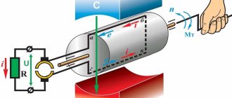
Principle of operation
Connection or disconnection of the switched electrical circuit is ensured by turning the contact knives. Depending on the design, the moving contacts can be rotated vertically or horizontally. The drive that imparts force to the rotating mechanism is a rod with a handle, with the help of which the operator controls the contact knives. The drive handles are mounted directly on the supports under the disconnector.
Manual control is used mainly on overhead lines up to 6 kV. Knives on lines of 110 kV and above are controlled by electric drives using metal cabinets located at a safe distance.
Main purpose and application
The need to use these disconnectors in modern energy networks is explained primarily by the need to maintain safety during the operation of equipment and transmission lines.
These devices are used in places where contact lines are connected to power supplies and for the purpose of safely performing switching operations during the operation of electrical networks.
Also read: Instrument current transformer
Disconnectors can be installed on the following equipment and lines:
- in complex transformer substations;
- as part of complete disconnecting installations;
- in capacitor units;
- in prefabricated chambers providing for one-way service;
- in input or distribution cabinets, on other equipment.
The use of disconnectors eliminates the risk of spontaneous switching on and off of connections, preventing abnormal and emergency situations.
Classification
The domestic industry produces high-voltage disconnectors of various types. They can be classified according to the following criteria:
- by number of poles;
- type of contact knife (rotary, chopping, swinging);
- installation location (open space or room);
- by control method: manual (using an insulating rod or levers), electromechanical, hydraulic, pneumatic.
In addition, devices differ in rated voltage and rated current for which they are designed. Products come with grounding switches (disconnectors RVZ, Fig. 4), with figured knives (RVF) and others.
Figure 4. RVFz 1063
The type of device can be determined by its designation.
The letters indicate:
- P – type of product, in this case a disconnector;
- N – external;
- G – horizontal installation;
- L – linear;
- Z – disconnector with grounding blades. The numbers 1, 2... indicate the number of grounding conductors;
- D – with two support-insulating columns;
- The numbers 10, 35, 110, 220 mean the rated voltage in kilovolts.
For example, RV is an internal disconnector, and the abbreviation RLND means that this is a linear type of device with two support-insulating columns for outdoor use.
Requirements
The main requirement for all high-voltage disconnectors is a design that provides for such a disconnection when the circuit break is clearly visible. Devices used to disconnect lines over 1 kV are subject to the requirements of GOST R 52726-2007, providing:
- thermal and electrodynamic stability of the structure;
- high quality insulation, capable of operating in various atmospheric conditions and withstanding all kinds of overvoltages;
- reliable switching on or off under all permissible conditions, including icing of structural elements;
- simplicity of design, ensuring reliable disconnection, ease of installation and operation.
Separate requirements apply to compliance with installation features, operating rules and preventive measures to keep disconnectors up to date.