The operation of electrical and electronic devices occurs due to the supply of mains current. The energy flow through the wires brings with it satellite electromagnetic fields. They pose a threat to the accuracy of the performance of their functions by electricity network subscribers. Network filters (SF) can solve this issue. You can always buy them in the form of network extension cords. Knowing the network filter circuit, the device is easy to assemble with your own hands.
Network filter
Operating principle of a surge protector
The AC voltage in the 220 V network changes in a sinusoidal form. The correct shape of the electrical impulse is “contaminated” by electromagnetic interference. A sine wave looks like a bending line of a pure signal, surrounded by a network of stray currents caused by phase imbalances, surges and voltage surges.
Mains current graph
Accompanying noise affects sensitive components of electronic circuits of various devices and equipment. The problem arises of clearing the current from parasitic formations. For this purpose, a surge filter (SF) is used.
SF is built between the mains current source and consumers. It consists of chokes and capacitors connected in a certain order. The work of the filter is to build the inductive reactance of the coils, which does not allow high-frequency interference to pass through. The device's capacitors cut off unwanted interference. Capacitors complete the circuit and do not allow parasitic pulses to pass through.
Surge filter for powering multimedia radio equipment
The proposed power filter, in terms of the level of protection it provides, in most cases, will be much more effective than the filters built into inexpensive industrial power strips.
About twenty years ago, the author of this article witnessed an unusual natural phenomenon. On a dark winter evening, on an overhead power line with a voltage of 0.4 kV, right on the wires, yellow-white balls about the size of a basketball began to appear out of nowhere, with a hiss, these balls at a speed of about 8 km/h began to roll in one direction along the wires like real balls, and when they reached the insulators attached to electric poles, they exploded in a salute of sparks. At the same time, the wires themselves shot electric lightning several meters long at nearby buildings.
When a few minutes later I entered the office premises, the following picture appeared before my eyes - lightning bolts up to one meter long were striking from branch boxes, light switches, and sockets in the direction of the nearest walls. A TV was plugged into one of these sockets, and it continued to work flawlessly, although a few tens of centimeters from the table with the TV, in the socket where its cord was inserted, lightning was playing with a brick wall. The TV was a Record-6 tube TV. All these phenomena lasted about ten minutes on a power line about 300...500 meters long. Although mostly wooden buildings were attacked by lightning, no fires broke out. A nearby 35 kV/0.4 kV power substation began to smoke, but the power supply was not interrupted. I have not yet had the opportunity to see such a phenomenon at least once again and record such an unusual show on video.
Modern radio equipment with switching power supplies is much more sensitive to various anomalous phenomena in the 220 V AC network than equipment with classic step-down transformers. The greatest danger comes from lightning strikes during a thunderstorm, which sometimes happen unexpectedly, when the thunderstorm seems to be somewhere far away, or when it seems to have ended half an hour ago.
For radio equipment, both direct lightning strikes into a three-phase 0.4 kV power network and lightning strikes into nearby objects are dangerous. Also dangerous for radio equipment are high-voltage man-made voltage pulses, for example, those occurring during switching of power supply to inductive loads connected to a 220/380 V AC network: powerful electric motors, transformers, powerful electromagnets, etc.
To increase the reliability of your home equipment, you can make a simple surge protector, the circuit diagram of which is shown in Fig. 1 . The device is intended for connecting to it televisions, radios, amplifiers, computers, computer office equipment and other similar consumers of 220 V / 50 Hz network current. If your household electrical equipment already has some protective filters, then you can turn on several such devices in series, which will increase the degree of protection. The design is intended for connection to regular power outlets and is not intended for installation in electrical distribution panels.
Rice. 1
An AC mains voltage of 220 V is supplied to the XP1 plug, the current passes through the fuse FU1 and is supplied to a two-link LC filter consisting of a two-winding inductor L1, two identical chokes L2, L3 and noise-suppressing capacitors C1 - SZ. Also in the device, three levels of suppression of high-voltage impulse noise are stopped.
The first link is made of two vacuum arresters FV1, FV2 with an operating voltage of about 1000 V DC.
The second protection element is implemented on a disk varistor RU1 with a classification voltage of about 620 V.
The third level of protection is implemented on two varistors RU2, RU3 with a classification voltage of 430 V. The same varistors can protect loads connected to the filter in the event of an accident in the power supply, when instead of a voltage of 220 V, 380 V appears in your sockets.
After such an incident, RU2, RU3 will most likely be hopelessly damaged with physical destruction of the case, sacrificing themselves, for example, to save your giant modern TV. The HL1 LED included in the diagonal of the rectifier bridge VD1 - VD4 lights up when there is supply voltage, in addition, the circuit R1, R2, VD1 - VD4, HL1 discharges capacitors C1 - SZ after disconnecting the filter from the power outlet.
Construction and details
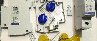
A view of the installation of elements is shown in Fig. 2 . Mounting is mounted, power lines are made with multi-core installation wire in PVC insulation with a copper cross-section of 1 mm2. Resistors can be used like MLT, RPM, S2-23, S2-33.
Rice. 2
Ceramic capacitor C1 type K15-5 or an analogue for a DC operating voltage of at least 3 kV with a capacity of 2200 pF...0.01 µF. Capacitor C2 type K78-2 or an analogue with a capacity of 0.033...0.1 µF for an operating voltage of 1000 V DC. SZ film capacitor with a capacity of 0.1...0.22 μF for an operating voltage of not lower than 250 V AC or not lower than 630 V DC; instead of an imported one, a domestic type K73-17, K73-24 is suitable.
The two-winding inductor L1 is wound on a 600NN ferrite rod with a diameter of 8 mm and a length of 70 mm, each winding contains 12 turns of homemade Litz wire 10 × 0.27 mm from winding wire. Litz wire is used for ease of winding. Before laying the windings, the ferrite rod is wrapped in several layers of office paper, which is then impregnated with tsaponlak. The finished throttle is impregnated with XB-784 varnish or similar. For chokes L2, L3, B36 armor cores made of low-frequency ferrite are used. Each inductor contains 30 turns of the same wire as L1. Winding on frames turn to turn; after each layer of winding, a layer of insulation made of varnished cloth, mica or thin paper is laid. The windings must be reliably insulated from the ferrite core, and the cores themselves must be insulated from any other current-carrying parts of the structure.
Vacuum arresters FV1, FV2 are taken from kinescope boards from imported TVs or monitors. Instead of two such arresters, you can install one more powerful one, for example, from Epcos for a voltage of 800... 1200 V. You cannot connect several low-voltage arresters in series. If there are no suitable arresters, one disk varistor for a classification voltage of 910 V, for example, FNR-20K911, can be installed in their place. The MYG20-621 varistor in this design can be replaced with FNR-20K621, FNR-20K681. Instead of varistors MYG20-431, you can use FNR-20K431, FNR-20K471.
LED L-1503GD green, lens diameter 5 mm, can replace AL307, KIPD40. Instead of 1N4148 diodes, KD510, KD521, KD522, KD209 are suitable. Diodes and resistors are installed on the circuit board on the connection side. The LED is installed on the front panel of the device. Fuse holder DVP-7, designed for fuses with a body length of 30 mm. More common fuses with a glass or ceramic body length of 20 mm are not suitable for operation in this device. The fuse holder is installed on the front panel of the device, which also houses a standard XS1 power socket without an external protective housing. With a connected load current of 10 A, about 4 W of power is lost on all structural elements, including 2 m of connecting wire with the XP1 plug, which is not much.
The housing for this filter must be made of non-flammable material. The author used a ready-made brass box with dimensions 130x104x48x0.6 mm. There should be no ventilation holes in the housing. The circuit board is installed in this housing on metal bushings. At the location of the circuit board, a U-shaped insulator made of dense electrical cardboard impregnated with tsaponlac is glued inside the box. For gluing, you can use XB-784 varnish. A faultlessly manufactured device starts working immediately and does not require adjustment.
This design is only an additional element of protection against abnormal voltages and impulse noise. Therefore, its presence in the power supply circuit does not negate the desirability of having protection units inside the end current consumers, for example, in a computer power supply, telephone “charging”, and in the input distribution panel. At the same time, in reality, due to savings or sloppiness, both the first and the second are often missing, and that puny varistor that is installed in your beautiful network extension cord-splitter for 5... 10 USD does nothing but ease the manufacturer’s conscience .
Literature
- Butov A.L. Surge filter for devices with commutator motors. // Electrician. - 2008. - No. 11-12. - P.93.
- Butov A.L. Surge filter from water filter cartridge. // Electrician - 2012. - No. 4. - P.78-79.
Author: Andrey Butov, p. Kurba, Yaroslavl region. Source: Electric magazine No. 10, 2015
Simple surge protector device
DIY laboratory power supply
There are two types of SF:
- Built-in.
- Stationary – multi-channel.
Built-in
Compact SF boards are part of the internal structure of various electronic equipment. They are equipped with computers and other complex equipment.
Built-in network filter board
The photo shows the SF device. The following parts are installed on the board:
- VHF – capacitor;
- toroidal throttle;
- additional capacitors;
- varistor;
- induction coils;
- thermal fuse.
A varistor is a resistor with variable resistance. If the standard voltage threshold (280 V) is exceeded, its resistance can decrease tens of times. The varistor performs the function of surge protection.
Stationary – multi-channel
The device body has several sockets. Thanks to this, it is possible to connect all existing electrical equipment in one room to one outlet through a filter. To remove high-frequency radio interference, a simple LC filter is used. Fireproof thermal fuses prevent power surges. Some models use disposable fuses.
How to choose a surge protector
Choosing network voltage stabilizers, filters and extension cords is not as easy as it seems. Experts identify several criteria that the device must meet:
- Consider how many ports the network extender should have. It is advisable that the devices have as many branches as possible, this will significantly save your time, reduce the number of cables in the apartment, and increase safety;
- All amplifiers have a certain limit of noise suppression, surge protection and power load capacity. It is especially important in this regard to calculate gateway devices and their characteristics. Also, think in advance how you will connect the splitter; you cannot turn on several powerful appliances at the same time (washing machine, hydrobox, air conditioners and stove);
- Check for UL gasket, make sure it is "transient surge voltage suppressors". Be sure to find out if the device is certified with the UL 1449 quality laboratory mark;
- Specify the purpose of the device: this is an extension cord for a computer, washing machines with water protection or audio equipment;
- Check the warranty and repair certificate. Some transformer single-phase and three-phase voltage stabilizers can catch fire due to overvoltage, but if they are certified, this should not happen.
Making your own surge protector
It will not be at all difficult for a radio amateur to make the simplest surge protector with his own hands at home. To do this, you need to build a small circuit inside the body of a power strip with several outlets. The picture below shows how to do this.
DIY SF
DIY power supply for 12V screwdriver
Install the SF in the extension cord as follows:
- Open the housing of the power strip.
- Resistors R1, R2 and chokes (inductive coils) L1, L2 are soldered into parallel branches after the switch and varistor.
- Then the branches are alternately closed through capacitor C1 and one resistor R3.
- Installation of the end capacitor C2 can be done anywhere between the sockets.
Important! If there is no room inside the extension cord housing for the second capacitor C2, then you can do without it. It is enough to adjust the parameters C1.
Chokes are used with open ferrite cores with inductance from 10 μH. Capacitors are selected in the range of 0.22-1 µF. The resistance of the resistors correlates with the planned power of consumers. At a load of 500 W, 0.22 Ohm resistors will be required. Resistance R3 must be at least 500 kOhm.
Basic parameters of network filters
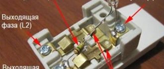
Cross-section of supply wires. Most often, a surge filter (Fig. 6) is produced with a core cross-section of about 0.75 or 1 mm2. This cross-section is considered sufficient since the maximum load current for which the filter is designed usually does not exceed 10 A.
A fuse is also installed for this current. If necessary, you can find a surge filter of increased power, the cross-section of the wires of which reaches 1.5 mm2. The fuse for such a device has a rated current of 16 A.
Rice. 6. Typical surge protector socket.
Length of the network supply wire. The standardized length of the filter power cord is 180 cm. For some models it can be 190 cm, 300, or even 500 cm. Number of sockets. Usually there are 4...6 of them (Fig. 7).
As a rule, all sockets have grounding “ears” (Euro type). There are filters with sockets of different types (1 - universal and 4, 5 - “euro”, Fig. 8).
Rice. 7. Set of sockets.
Number and types of fuses. Fuses are included in the network filter to protect against burnout of varistors in the event of large impulse noise and to disconnect consumers in the event of a short circuit or prolonged overload of the load circuits.
For greater reliability, some manufacturers, in addition to thermal fuses, also install self-recovering fast-acting fuses (based on metal-organic semiconductors).
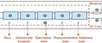
Scheme of SF protection against network interference
A typical network filter circuit is the basis of all devices of this type, with the exception of additional details. The classic is connecting to the points: Ground, Phase and Zero. A varistor VDR 1 is installed at the input. It suppresses voltage surges in the mains current. With a high voltage surge, the resistance of the varistor drops sharply, thereby preventing the interference from passing further through the circuit.
To dampen small voltage changes, inductor Tr1 and three capacitors C are used. Capacitors C1, C2 and C3 are reactive radio components that constantly change the resistance level. It increases sharply when the current frequency changes.
Normal current passes through the filter unimpeded. At the same time, high-frequency interference is delayed in the SF. The filter resistance is directly proportional to the current frequency. Both indicators increase simultaneously, which makes it possible to delay interference on the way to the consumer.
Note! A three-wire power supply network may be subject to interference in the phase-zero, ground-phase, and ground-zero sections.
Effective suppression of such negative phenomena is carried out by normal standard grounding of the SF.
Ways to Improve the Filter Circuit
There are many options for improving the network filter circuit. One of them is ingenious and allows you to significantly save energy consumption. The essence of the method is as follows:
- Open the housing of the multi-connector SF extension cord.
- One of the current-carrying busbars is cut.
- The segments are connected to a 5 volt relay, designed for switching current 3A, 250 V.
- The other two relay contacts are connected by wires to a USB connector at the end.
- The connector is connected to the USB input of the TV.
The result is a controlled power system consisting of a TV, a digital set-top box and a satellite dish power supply. If previously, when the TV was turned off, all parts of the system remained in standby mode, then with the upgraded filter they are completely turned off. As soon as you turn on the TV using the remote control, all the switched devices are also activated and vice versa.
Additional Information. Various modernized SFs can always be found on the radio market, but they are quite expensive. Therefore, it is much more profitable to improve the device yourself.
In another case, they take the path of adding an LC filter to the SF, which, in addition to suppressing interference from the network, reduces mutually occurring electrical interference from connected consumers.
A standard varistor (470 V) often does not trip the automatic fuse. It is replaced with a similar device designed for a voltage of 620 V. This allows you to suppress interference from a running washing machine, vacuum cleaner and other powerful electrical equipment.
Home craftsmen equip surge protectors with audible alarms. When the voltage level in the network exceeds 280 V, the filter notifies you with a signal.
How does a surge protector work?
The devices in question are:
- built-in;
- stationary.
The first option is part of an electrical device and is installed directly in its case or power supply. Structurally, the product is made of capacitors, tanks, coils, a thermal fuse and a varistor. The latter is designed to protect the device from power surges.
Stationary devices are designed as a separate device with several sockets. This allows you to simultaneously connect several pieces of electrical equipment to the power grid using just one outlet. RF interference removal is achieved using an LC filter. Voltage surges are prevented by fireproof fuses.
What's inside the filter
The line filter housing contains:
- filter elements;
- varistor;
- switch;
- rosette elements.
A network cable is used to connect the filter to the network. A similar design is used in high-quality filters.
Surge filters for household appliances
To safely connect modern household appliances, it is recommended to use surge protectors. They are designed not only to suppress interference, but also to smooth out voltage surges. To power old refrigerators, in which only the compressor motor and the backlight were used as electrical components, changes in mains voltage are not a problem. However, modern refrigerators are equipped with complex electronic computing systems, and the use of a surge protector is extremely necessary.
The situation is similar with the washing machine. If you have a surge protector, in the event of short-term power surges, the equipment will remain operational thanks to the accumulated energy in the capacitors. Washing machines equipped with touch controls must have filtering devices installed from the factory. Otherwise, the sensor almost immediately fails during power surges.
All this indicates that filtering devices should be installed in the apartment to power equipment. In addition, today there is a wide selection of such devices designed for consumption of both 1 kW and 4 kW.
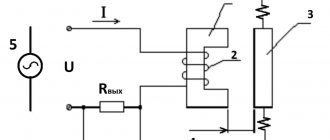
Line filter with 2 winding choke
SF based on a choke with two windings is used for sensitive audio equipment. Speakers are sensitive to power supply interference. If any occur, the speakers distort the sound and emit extraneous background noise. Radio equipment connected to the network via a SF with a 2-winding coil is protected from such interference.
The circuit is assembled on a separate printed circuit board. You will need several capacitors and a homemade inductor. It is made as follows:
- A ring made of ferrite grade NM with a magnetic permeability from 400 to 3000 can be taken from old electrical equipment.
- The magnetic core is wrapped in cloth and coated with varnish.
- PEV brand wire is used for winding. Its cross-sectional area depends on the magnitude of the load. Powerful consumers require a significant increase in this parameter.
- Winding is carried out with two wires in different directions.
- Make 10, 12 turns of each conductor.
- Capacitors are installed at the beginning and end of the circuit. They must withstand voltages up to 400 V.
SF with 2 winding choke
The windings of the inductor are connected in series order. Therefore, the magnetic fields of the coil are mutually absorbed. When a high frequency current passes, the resistance of the inductor increases sharply. Capacitors absorb and short-circuit interference.
The printed circuit board is placed in a separate metal case. As a last resort, the circuit is fenced off with metal sides. This is done in order to eliminate additional interference from stray electromagnetic fields.
With each new generation of electronic equipment, increased demands are placed on the quality characteristics of the mains current. In order not to have to repair sensitive electronics, you must connect them through surge protectors. If you need to filter the current for a small number of consumers, then you can take the economical path and make a surge protector with your own hands.
DIY surge protector
The simplest filter circuit consists of a switch and a varistor, this is what it looks like:
V1 is a varistor, its marking “471” means that its operating voltage is 470V, and the larger its diameter, the more energy it can absorb without exploding. This means that the larger the varistor you install, the better, as long as it fits in size. Here is an example of a surge protector assembled according to this scheme, but in a factory version. From the above it follows that this is a cheap device that does not filter what it should, but only dampens impulses.
In order for your surge protector to actually be a noise filter, you need to add a filter element - a choke.
Schemes are, of course, good, but how to make a surge filter from improvised means? Simple enough! Almost always, when someone who likes to tinker with something, you can find an old unnecessary or non-working power supply, it has such a filter at the input. All that remains is to unsolder it. In the photo he stands in the corner of the board closest to us.
This is a choke with two windings, a phase passes through one of them, and zero passes through the other, so the inductance is part of the network filter and reduces the level of interference.
By the way, the power supply can work without it, many Chinese make their products this way, this is often found in cheap power supplies for computers and not only.
If you do not find such an element in your supplies, you can look for a ferrite ring with a magnetic permeability of 400-2000 nm and wrap it with PEV-2 wire (can be wound from a 50 Hz network transformer). Wrap it around the ring as shown in the picture.
Do not allow inter-turn short circuits and leave gaps as shown here, otherwise you will get fireworks from the phase jumping to zero. Cut the loop at the end; ideally, wind it with two wires at once. Before winding, apply an insulating layer, for example, made of varnished fabric, to the ring.
A good diagram that is easy to do with your own hands looks like this:
And here is a version of its implementation “in hardware”. A pair of filters from the power supply is taken as a basis.
It is better to use ceramic or film capacitors. They can also be taken out of the power supply; they are often found there in a rectangular case with sharp corners (parallelepiped).
If you have an unnecessary power supply, you can simply cut off part of the board with the filter and use it. Here is an example in the photo indicating what needs to be sawed off to get a surge protector in a couple of minutes.
And here is another version of the scheme to repeat. This is what is used in many ATX power supplies:
A surge protector is a useful and simple device that is not difficult to make yourself at home. And if we take into account all the abundance of technology that has passed through modern ordinary people and the fact that many have several unnecessary and inoperative devices, then spare parts are literally lying around under our feet. Finally, we recommend watching several interesting video instructions for assembling a homemade surge protector:
Source