Dimmer connection diagram
Before starting electrical installation work, you need to decide how and from what location it will be more convenient to control the dimmer. To do this, a dimmer connection diagram is drawn up. Any home handyman with basic electrical installation skills can connect any of the circuits he needs with his own hands. To do this, you first need to turn off the electricity in the room where the dimmer will be installed, and also check the absence of a phase with an indicator screwdriver.
Scheme No. 1
The simplest and most common circuit consists of a dimmer and lamps that are connected to it in series. The dimmer is placed in the gap in the phase wire, marked “L”. In this case, one wire from the junction box is connected to the “L” terminal with an upward arrow, and the second wire is connected to the “~” terminal with an inclined arrow. According to this scheme, a dimmer is installed instead of a regular switch.
Scheme No. 2
The circuit is convenient to use when the dimmer is installed together with a switch, connected to the phase wire break in front of the dimmer. Very often, a dimmer circuit with a switch is installed in the bedroom, when the dimmer is located near the bed and allows you to adjust the lighting without getting up from it, and the switch is located at the entrance to the room.
Scheme No. 3
A circuit with two dimmers allows you to place the controls in different corners of the room. This is especially convenient in large rooms with several light sources, for example, sconces and chandeliers. To connect according to this scheme, it is necessary that three wires go from each source to the distribution box, two of which are connected by jumpers, and the phase comes to one third contact, and from the second regulator the third contact goes to the lamp.
Scheme No. 4
In a long corridor or walk-through room, a circuit with two pass-through switches is usually connected. The lights are turned on and off from different ends of the corridor or room. In this case, pass-through switches are used.
Schemes and methods of connecting a dimmer
There are several options for connecting a dimmer to a lighting network, but we will present only the most commonly used circuits today.
Scheme one
The simplest one, since we are talking about installing a regulator instead of a traditional switch. To begin with, the key switch should be removed (of course, having de-energized it in advance). To do this, remove the cover of the de-energized device key - it is under it that the screws securing the housing are located. If there is no plastic box, it must be installed after dismantling the breaker. It can be a simple box - the kind that is used for sockets.
If this dimmer connection diagram is used in relation to a monoblock model, then the technology is the same - the phase cable is placed in a gap. It must be connected to the terminal that is designated by the letter L and has an arrow pointing up. As for the second cable, it must be connected to a different terminal (a wavy line with an inclined arrow).
Scheme two
This scheme is somewhat more complicated (but at the same time much more convenient) and is used, as a rule, for bedrooms. The peculiarity is the serial connection of the switch and dimmer to one phase cable going to the lighting device. It is worth remembering that the switch should be located first in this line, and after it the dimmer itself. The most popular option is to mount the switch next to the door and the dimmer near the bed.
The main advantage of this scheme is that you, the user, will be able to adjust/turn off the lighting without even getting out of bed! And if, when leaving the room, you use the circuit breaker to turn off the light, and when you return and turn it on again, you will notice that the brightness level of the lighting is the same as you set before.
Scheme three. Pass-through switch
It is rightfully considered the most difficult option, since it involves installing a pass-through switch. Despite the fact that the installation process is highly complex, the convenience of the scheme is obvious, and therefore it is often used for through rooms, long corridors, stairs between floors and other similar places. In short, the essence of this method of adjusting the intensity of lighting is to turn on the light in one place and then turn it off in another.
What else is special about pass-through switches? And the fact that they are, in fact, more switches - they can switch between lines, and therefore turn on at any location of the key. An analogy can be drawn with railway switches. But the connection diagram for a dimmer with a pass-through switch is presented below. The phase, as you can see, goes to the first switch, while it goes to the lighting device from the other. A two-core cable is used to connect the breakers together.
Now let’s look at how a dimmer will function in such a circuit. It must be connected after the last breaker, so that the lighting intensity can be easily adjusted regardless of the position of the switches. However, if the dimmer is turned off, the light will go out and, characteristically, will not react in any way to the pass-through switches (and this is not surprising, because you will open the circuit).
Types of indoor dimmers
Room lighting controllers are divided into two groups:
- Mechanical;
- Sensory.
Illuminated switch
Mechanical regulators have the simplest design. On the outer surface there is an adjustment knob mounted on the variable resistor shaft.
Note! The fact that the lighting is controlled using a variable resistor does not mean that this device operates using a rheostatic method. A variable resistor changes the parameters of the control pulses supplied to the thyristor.
Mechanical dimmer
The undoubted advantage of such regulators is that in the off position the network wires are mechanically open, and the light is always turned on only from the minimum voltage level.
In turn, touch devices also have a large number of options, including:
- Touch switch with mechanical adjustment;
- Touch switch with brightness control without mechanical devices.
The first type is completely identical to the mechanical regulator above, except that the light is turned on and off by touching the sensing element. The lighting turns on immediately to the preset level.
Touch-mechanical regulator
Fully electronic devices perform adjustments according to a given algorithm by touching the corresponding sensitive elements. The presence of a built-in microcontroller allows programming the device using a variety of operating algorithms. You can set the desired lighting level at a certain time of day. Regulators with a microcontroller can de facto be used with a remote control.
Touch controller
All of the listed options can be designed to adjust the lighting of one lighting fixture, or for several. Externally, they differ in the presence of several keys, visually separated from each other.
Dimmer Basics
A standard dimmer is connected like an ordinary switch, i.e. into an open circuit in the power supply of the lighting device. The dimensions of the regulator in question and the fasteners for installing it in a niche also coincide with similar parameters of a simple switch. Consequently, anyone who has an idea of how to connect traditional light switches can handle installing a dimmer. The only important point: the terminals to the load and phase must be connected strictly in accordance with the diagram provided by the manufacturer.
Basic information about dimmersDimmerDimmer
All dimmers presented today can be divided into 2 large classes: rotary (also known as rotary) and push-button (electronic).
Dimmer
Table. Some types of dimmers
| Types of dimmers | Explanations |
| Dimmer for incandescent lamps and halogen lamps with a voltage level of 220 V | In this case, it is the magnitude of the applied voltage that determines the intensity of the lamp filament. |
| Dimmer designed for low-voltage halogen lamps powered via a transformer | Responsible for converting the output voltage of the dimmer to the desired value. If the lamps are designed for a voltage of 12-24 V, then an electronic transformer is needed that provides soft control of the current source. |
| LED dimmer (LED dimmer) and dimmer for fluorescent lamps. | The task of a dimmer for LEDs is to quickly produce the specified results and smoothly regulate the strength of the light flow. |
| Touch dimmer | The main difference between the touch device (viko dimmer) is the ability to regulate the light output by barely perceptible touching a certain area of the button. Can be equipped with an infrared receiver for remote control. |
| Rotary dimmer | Assumes easy rotation of the rotary element. |
| Push dimmer | Involves multiple key presses |
| Single dimmer | Can be used both for one lamp and for a number of light sources combined into a common group. |
| Group dimmer | For regulating several light sources at once. |
Rotary regulators are the most widely used. Control of lighting intensity with such devices is performed by simply turning the knob in the desired direction. Push-button dimmers are more convenient and flexible in terms of controlling light brightness. Additionally, electronic dimmers allow you to connect buttons in parallel and control lighting from several different places. In practice, the number of such places is limited to 3-5. In this case, the length of the wire should not exceed 10 m.
Dimmer Basics
There is also a group of devices on the market that allow you to control the brightness of lighting remotely using a remote control. However, such dimmers are an order of magnitude more expensive than the analogues discussed above.
The most popular, as already noted, are rotary type dimmers. These are the ones we will look at in this guide.
Self-installation of the dimmer
The steps to replace a switch with a dimmer begin with choosing a dimmer. Device design – rotary, rotary-push, touch, etc. in this case it is unimportant. The first thing to start choosing is the type of controllable lamps. You can find it in the instructions for the device or look for letter markings on the body.
| Letter marking | Symbolic marking | Load type | Controllable lamps |
| R | Ohmic | Incandescent | |
| C | Capacitive | With electronic ballasts | |
| L | Inductive | Low voltage halogen lamps with winding transformer |
Many dimmers allow mixed loads (RL, RC, etc.). If you plan to adjust the brightness of fluorescent lamps, you need to make sure that their packaging bears the inscription “dimmed”. Otherwise, the system will not work.
Important! Before attempting to connect an LED lamp, you should also make sure that it is marked “dimmable”. If there is no such inscription, then the lamp has a driver installed in the form of a current stabilizer, and an attempt to adjust the brightness by controlling the average current from the outside will be futile. This does not apply to LED strips - in them, the current through the LED is limited by ordinary resistors and the glow is well controlled by an external average voltage. Therefore, there are no “non-dimmable” LED strips, despite the tricks of marketers.
The second important parameter is the maximum power. It should cover the total power of the switched luminaires with a margin. Based on this characteristic, there is no need to choose a dimmer “on the edge”. The rest is execution, design, etc. - to the taste and wallet of the buyer.
Designation of a dimmable lamp.
What you need to prepare
Dimmer installation begins with the selection of tools. At a minimum, you can get by with two screwdrivers:
- large for tightening (loosening) the dimmer (switch) blades;
- smaller for clamping and loosening the wire fastening terminals.
The following will not be superfluous in this work:
- indicator screwdriver;
- multimeter
You may need another small tool (pruning knife, etc.).
Removing the standard switch
It is advisable to start installing any dimmer instead of a switch by checking the installation - you need to make sure that it is the phase wire that opens. In 99% of cases it will turn out that the installation was completed correctly. But we must exclude all surprises. If a careless technician places a switch in the zero gap, then this will not affect the performance of the system without a regulator (unlike safety). But the dimmer needs the correct phasing. You can check this using a voltage indicator (indicator screwdriver). If everything is fine, then you can proceed to the next step. If not, then there is a lot of work ahead. And it’s better to think about whether dimming is worth it (safety is definitely worth it).
The second and very important step is to turn off the power to the lighting system. This is usually done at the switchboard.
Important! After disconnecting the switching element, it is imperative to check that there is no voltage directly at the workplace. You cannot trust the diagrams in the panel and the inscriptions on the circuit breaker.
After making sure that the switch is not energized, you need to remove the cover of the switch, loosen the terminals to which the wires fit, and the petals that hold the switch apart in the box. After this, the switching device must be carefully removed and the wires pulled out from the terminals. This must be done carefully so as not to break off the exposed areas.
Short video instruction.
Dimmer installation
The regulator has the same dimensions and installation dimensions. Therefore, installation is carried out in reverse order:
- the dimmer is installed in its seat;
- the wires are connected to their terminals;
- by releasing the petals, the regulator is fixed in the box;
- tighten the terminal screws to secure the wires;
- The regulator cover closes.
This completes the dimmer connection. You can apply voltage to the lighting system and test the regulator in operation.
Types of dimmers
All dimmers that are currently on sale can be divided into 2 groups - rotary (with a regulator - potentiometer) and electronic, controlled using buttons.
When adjusting (dimming) with the potentiometer knob, the brightness depends on the angle of rotation. And one rotary dimer works like one switch; it is impossible to achieve more from it. I'm talking about pass-through switches, parallel-series connection, etc. My not entirely successful experience is described on SamElectric in the article Connecting two dimmers in parallel.
A push-button dimmer is more flexible in terms of control flexibility. You can connect several buttons in parallel and control the dimmer from any number of places. Of course, this is theoretical, in practice the number of control places is limited to 3-4, and the maximum length of wires is about 10 meters, and the circuit can be critical to interference and interference. There are also remote dimmers controlled via radio or infrared.
The price of dimmers with a regulator and with buttons differs by an order of magnitude, because a button dimmer (for example, a Legrand dimmer) is usually assembled using a microcontroller. Therefore, rotary dimmers are much more common, which we will consider below.
There are also industrial varieties of dimmers in the form of solid-state relays with resistor control; this type of dimmer is discussed in the article about solid-state relay connection diagrams.
Application requirements
It should be noted right away that the simplest dimmers that are used at home can only be used to control incandescent and halogen lamps. If they are connected to LED strips and fluorescent light bulbs, both devices will fail in a short period of time. This is why it is necessary to choose dimmers based on which light bulbs they will control.
The remaining requirements when connecting a dimmer are as follows:
- The minimum power of the lamp to which the connection will be made should not be lower than 40 W. If you ignore this point, the service life of the regulator will be noticeably reduced.
- It is not recommended to install the dimmer in a room where the temperature is above 25 o C. Overheating of the device will negatively affect its operation.
- The phase conductor must be broken, which is connected to the connector marked L. Connecting the zero is strictly prohibited, just like when connecting a standard light switch.
- To adjust the glow of fluorescent lamps, choose products with the appropriate designation, which indicates that the lamp can be used for dimming.
- If you decide to use a dimmer together with LED lamps and strips, you need to buy a device of a special design that can work with such a light source. Leading manufacturers: Schne >
These are all the requirements that you must adhere to in order to correctly connect the dimmer with your own hands!
How to connect a dimmer to an LED lamp or strip
There are no fundamental differences in the connection method. The only peculiarity is that the dimmer is placed in front of the controller of LED lamps or strips (see diagram). There are no other differences.
How to connect a dimmer to LED lamps and strips
Everything is exactly the same: the dimmer is placed in the break of the phase wire, but its output is fed to the input of the controller of the led lamp or strip.
Connection diagrams
First of all, before installing the mechanism, it is necessary to select the most optimal connection diagram. The circuit may contain a dimmer or a simple switch. Such connections are convenient and easy to install, so you can assemble them yourself, without the help of specialists. Let's look at each connection separately.
- Standard connection. This is the simplest and fastest connection. Instead of a switch, a dimmer is installed. When using a three-wire network, ground and zero go to the lamp, and the phase goes to the break.
- Serial connection. This scheme is very simple. Its installation is as follows: it is necessary to place two dimmers, with the help of which one light source will be regulated, in different places. The connection must be made so that three conductors are supplied from the distribution box to each pass-through dimmer. The mechanisms are connected to each other through the first and second contacts using a jumper. The third contact from the first mechanism enters the phase, and the second device is connected to the lamp. This connection is convenient to use in a long corridor or in a large room. There is another option to turn on and control the brightness of the lamp from several places. This is the use of a pass-through switch (2nd scheme).
- Parallel connection. How to connect such a connection? The two regulators are completely dependent on each other and act not as switches, but as switches. The disadvantage is that each pass-through dimmer controls only its own section of the half-cycle. This means that if one pass-through dimmer is set to 100%, then it is impossible to adjust the brightness of the lighting with the second dimmer.
- Connection with a simple switch. This scheme is possible in the bedroom. For example, one pass-through dimmer is installed near the bed, and another pass-through switch is installed at the entrance to the room. This will allow you to adjust the lighting without getting out of bed. Installation of such switches is carried out like a regular connection. The circuit with the switch looks like this:
Pass-through switches and dimmer
There is a lighting control scheme using pass-through switches. They form a system with which you can turn the lighting on and off independently from two points spaced apart in space. For example, it is convenient to turn on the light at the entrance when crossing a long corridor, and turn it off when leaving.
Control circuit with pass-through switches.
Such switches, instead of one contact for closing-opening, have a group of contacts for switching. With the advent of dimmers, the idea of installing a dimmer in this circuit appeared. For example, to adjust the brightness level of a lamp depending on the environment.
Control circuit with dimmer and pass-through switches.
The dimmer can be installed on one side. At the same time, it can serve as an additional light switch - if necessary, completely break the circuit. The best idea is to use a dimmer with a changeover group of contacts instead of a single switch-switch - switching occurs when you press a key (turn-push type).
Control circuit with dimmer and one pass-through switch.
It is unlikely to be possible to install pass-through dimmers on both sides for two reasons:
- The design of the regulator does not imply access to the changeover contact;
- The first dimmer to the source will “cut” the sinusoid so that the effect of the second on the brightness will be unpredictable.
Here there is an unplowed field for lovers of experiments and alterations. The main thing is not to forget about safety precautions.
Installation of the regulator and connection to the network
After making sure that there is no electricity through the wires, you can safely remove the insulation by 12-15 mm (the wires themselves should protrude 8-10 cm from the electrical box).
The required length of wires from the wall is 8-10 cm.
After performing this operation (to avoid tearing out the wires, it is better to use special stripping tools), connect the phase conductor to the regulator terminal marked with the letter L (phase). Sometimes in other models of foreign manufacturers it may be marked with an arrow pointing outward - “exit” or the letter P).
Connecting the phase wire to the regulator
The blue neutral wire is connected to a terminal marked N. Sometimes on other models marked 0 or an arrow pointing to the terminal - "input").
Neutral conductor connection
The grounding cable is usually not involved in the connection, so its tip is insulated - inserted into a small clamp (see other methods of possible insulation here).
The ground wire is insulated using a separate terminal
If your light controller model provides this, the ground wire is attached to the terminal on the metal panel marked with this ground symbol.
Grounding the 220V regulator
Some models of regulators must be grounded by connecting a cable to their metal panel.
All that remains is to insert the regulator mechanism with the connected wires into the electrical box and mechanically fix it there using screws and brackets.
The controller mechanism is inserted into the box
It is important to attach the panel correctly; the reliability of the fixation of other parts of the regulator and the operation of the entire device depends on this. The device is screwed in with screws
The device is screwed in with screws
Place the top cover on the controller and secure it with a screwdriver (or latches, depending on the dimmer model).
The device is equipped with a top cover, which must also be secured with a screw
The handle is inserted into the desired location on the regulator cover.
The handle is inserted and the dimmer is assembled
Now you can turn on the electric current in the apartment and check how the installed lighting controller works.
Analysis of connection diagrams
The choice of circuit depends on many factors, including the dimmer model, connection method - separate or with switches, the number of dimmers or lighting devices.
You should also take into account a very important point: different devices are used for incandescent lamps, LED lamps and strips, and low-voltage halogen light sources.
Testing a remote control dimmer connected to an LED strip. LED strips are successfully used to illuminate suspended two- and three-tier plasterboard structures
The most basic dimmer connection diagram can easily be confused with the switch installation diagram, since it actually repeats it one to one. Wiring is usually done with a two- or three-wire wire, depending on the grounding system. In new houses, it is recommended to use a wire with three cores - VVGng with a cross-section of 1.5 mm².
Three wires are pulled from the machine in the electrical panel: ground - to the metal body of the chandelier or lamp, zero - to the lamps, and phase - to the dimmer, to the input terminal
But often a chandelier has many arms, and the dimmer is used to control a group of separately located lamps. In this case, it is advisable to install two devices instead of one, so that the lighting level of two separate groups can be controlled.
The fundamental difference is in the number of load wires. One common phase is supplied to the regulator, and at the output there are two phase wires directed to different groups of lamps. Accordingly, zero is also divided by two
How does the connection occur if, instead of setting up control for conventional or energy-saving lamps, it is necessary to set up control for LEDs? Usually, complete with strips or lamps, along with a dimmer, there is an adapter from 220 V to 12 V. This can be a power supply that is plugged into an outlet.
Both wires from the converter are pulled to the dimmer, connected according to the diagram to the required connectors, and from the output terminals they are supplied to one lighting device or several lamps connected in parallel
One or more pass-through switches are often used in conjunction with a dimmer - the electrical network with such a kit becomes more advanced in terms of ease of use. The location of the switch is determined in different ways: it can be between the panel and the dimmer or between the dimmer and the lamp.
The circuitry of pass-through devices differs from a standard device, and this must be taken into account when connecting
The main attention is paid to connecting the phase conductors in both devices. Finally, let’s look at the order of arrangement of wires and terminals for a standard dimmer connection - after all, it is this that is the most popular in everyday life
The simplest diagram that can serve as a standard for connecting a standard regulator. The phase conductor is supplied to the input, and from the output, the adjacent terminal, it goes to the lamp. The listed examples are only a small part of all possible schemes for installing the device. To make an error-free connection, you must use the manufacturer's instructions as your main guide.
Ceiling chandeliers - varieties
According to the number of lampshades, there are:
- chandeliers with one shade or lampshade (single-arm);
- with two shades or lampshades (double-arm);
- three-arm (with three shades), etc.
Basically, the number of lampshades depends on the style of execution (classic, loft, modern, etc.) and design. Moreover, the more shades and lamps on a chandelier, the greater the lighting power and, as a rule, the greater power consumption of electricity. The larger the area a given lighting device can illuminate.
By type of control, chandeliers are divided:
- wired control (two or three wire connection, plus a grounding contact if the chandelier has a metal structure);
- wireless control (via radio or from a phone via Bluetooth);
- combined options.
If you haven't bought a chandelier yet, just plan to do so
In this case, it will be very important to determine what type of wiring is installed in your apartment or house. The choice of a chandelier with a suitable connection diagram and control option depends on this
12 connection diagram options
Below is a table to help you make this choice. It is enough to determine what type of wiring you have and what switch is installed. If you select the right chandelier, no major alterations or interventions will be required in your existing wiring diagram. With the exception of some options, where there is a “change required” mark. We will discuss these changes below when we take a closer look at connecting the chandeliers of these models.
To decide on the choice of chandelier and connection option
- You need to determine your wiring type (2, 3 or 4 wire). Just look at the ceiling and see how many wires you have coming out of the ceiling in the place where the chandelier is attached.
- Which switch is used to control the lighting (in table 1, 2-key or dimmer).
- We select from the table the desired functions that correspond to the option number of your electrical wiring.
- And next to it, in the column, we see which chandelier performs these tasks.
You need to pay attention!
If you have 3 wires coming out of the ceiling, then in this case your wiring may have 2 “scenarios”
The difference will be that according to one option, one “phase” will come from the switch to the chandelier, and in the other option there will be two – “L1” and “L2” (pay attention to the number of keys on your switch)
If your wiring has 4 wires, then you can use any type of chandeliers and any controls here.
How to connect a dimmer instead of a switch
Recently, people are increasingly replacing conventional switches with dimmers. Changing a switch to a dimmer is very simple. The switch has two outputs (two terminals), and the dimmer also has two terminals. We simply connect the dimmer instead of the switch, using the same wires that were connected to the switch.
Polarity doesn't matter. However, if you have determined where the phase is using a phase indicator (indicator screwdriver), then it is better to connect the phase conductor to the L terminal of the dimmer. Just for order.
Turning on a light bulb through a dimmer
The only condition that the manufacturer imposes is to comply with the connection of the terminals to the phase and to the load. Although, as practice shows, you don’t have to worry about this - everything works well with any connection.
If previously the chandelier was turned on through a two-key switch, then through the dimer all the bulbs will light up (glow) simultaneously. We connect a phase to one terminal of the dimmer, and the other two wires to the second.
Kinds
The simplest dimmer works based on variable resistors (rheostats). This method of adjusting lighting is considered ineffective and has low efficiency due to overheating and the need for cooling. Nowadays, manufacturers no longer mass-produce such devices; most often, radio amateurs make them themselves.
The regulator, which is based on the operation of an autotransformer, produces an almost ideal sinusoidal curve at the output. But such a device is large in size and weight, and adjustment will require considerable effort.
The most popular at the moment are electronic dimmers, which are based on the operation of thyristors, transistors and triacs. It is precisely they that cannot be used with equipment that requires a sinusoidal power supply. Such regulators have another drawback: during operation they create interference that interferes with the normal functioning of radios and other sensitive devices. However, despite the listed disadvantages, electronic dimmers are used more often than others, due to their low price, small size and available additional functions.
In terms of execution, the regulator can be:
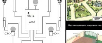
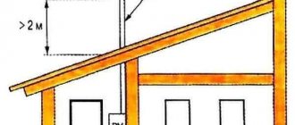
- Modular. They are installed in the electrical panel. The connection diagram for a dimmer of this design works with incandescent and halogen lamps through step-down transformers. To make them more convenient to use, the dimmer has an external button or a key switch. As a rule, a modular type of dimmer is used to regulate the brightness of lamps at the entrance gate, flights of stairs or yard lighting.
- On a cord. You can call it a mini-device that regulates the lighting of lamps that are not directly connected to the general electrical network, but are connected through a socket and plug (table lamps, sconces, floor lamps). This regulator only works with incandescent lamps.
- Monoblock. Externally, it is very similar to a regular switch. Works with different types of lamps; as a rule, this is indicated on the housing. The device is installed in the electrical circuit for a phase break; this dimmer is mounted instead of a switch.
Monoblock options are often used in apartments. In private residential buildings, it is convenient to install modular devices when you need to control the light in the adjacent area.
It is worth noting that there are still walk-through models of dimmers; they work on the same principle as walk-through switches, that is, the light can be adjusted in two places.
Device and types
Dimmers are made on the basis of different element bases. They all have their own characteristics and disadvantages. And to understand what a dimmer is and how it works, you need to understand what a specific device is made of. So, there may be options:
Thyristor dimmer circuit
When choosing a device, it is not so important to know what type it is, but rather to take into account the nature of the load to which it will be connected (incandescent and LED or fluorescent and energy-saving lamps).
By type of design, dimmers are:
Modular dimmer and its connection diagram
The dimmer on the cord can be installed on any table lamp, sconce, floor lamp (with an incandescent lamp)
Dimmer for installation under a switch
Connection diagram for dimmer switch
Rotary and rotary-push models do not differ in appearance
Keyboards are like switches
Touch dimmers are good because they can be remote controlled
In private houses and apartments, monoblock dimmers are most often installed. A modular design can also be useful in a house - to change the brightness of the lighting in the local area with the ability to control it from the house. For such cases, there are models that allow you to control the lighting from two places - pass-through dimmers (work on the principle of a pass-through switch).
Dimmer purpose
The purpose of a dimmer is to change the brightness of lighting devices. Adjustable light switches allow you to achieve any lighting intensity: from dim light to extremely bright. The use of dimmers makes double or triple switches unnecessary, and there is no need to buy expensive lighting fixtures with voltage controllers.
Note! To control the light intensity of energy-saving light bulbs, you will need a special device - an electronic starter. The advantages of dimmers include the following characteristics:
The advantages of dimmers include the following characteristics:
- light brightness control;
- setting the brightness change time;
- remote control control;
- long service life;
- programmed artistic flickering, creating backlit paintings;
- economical energy consumption (some models).
Disadvantages of dimmers:
- excessive electricity consumption in some cases;
- creating radio interference that interferes with the operation of electrical appliances;
- small loads cause dimmers to malfunction;
- The operation of dimmers often leads to unwanted flickering of the light.
How to install a dimmer correctly - detailed instructions!
As a result, I would like to familiarize myself with the procedure for installing a regulator instead of a simple switch. The replacement process itself in this case is not complicated, since both devices are mounted using almost the same technology. All you need to do is become familiar with this technology and act in accordance with the guidelines below.
Step #1. First, turn off the power supply; you can also additionally check whether it has really been turned off, using a special indicator screwdriver for this.
Step #2. After this, you can remove the breaker button that is installed.
Step #3. Now unscrew the screws that secure the decorative frame of the circuit breaker, and then remove it.
Step #4. Unscrew the mounting screws and remove the device mechanism from the mounting box. By the way, you can later install the dimmer itself in the same box.
Step #5. Unscrew the electrical cables that are connected to the switch.
Step #6. After this you will see a couple of loose wires.
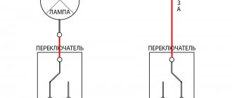
The first wire (and it will be a phase wire) is connected to the breaker itself, while the other is connected to the lighting fixture. Carefully read the diagram presented in the manufacturer's instructions for the dimmer; or, alternatively, this circuit may be present on the cover of the device housing.
As we have repeatedly mentioned above, when working with a dimmer, you must act in strict accordance with the connection sequence recommended by the manufacturer. So, the phase wire (and here it is marked in red) is connected to the dimmer terminal (it is marked L-in). The second cable (in this case, orange) must be connected to a different terminal - L-out.
Step #7. Place the dimmer in the remaining mounting box
To perform this simple operation, carefully bend the cables and insert the dimmer into the socket box. After that, tighten the screws, install the decorative frame, and secure it with the appropriate screws. Now all that remains is to install the adjusting wheel
Now all that remains is to install the adjusting wheel.
Step #8. Once the installation is complete, check the regulator for functionality - this will require reconnecting the power supply. Turn the handle of the device until you hear a characteristic click, moving in the opposite direction to the clockwise movement. When this very click sounds, the voltage on the light bulbs should increase, as evidenced by a gradual increase in the brightness of the lighting.
That's it, the device is connected and, as you have already seen, it works quite normally. Now you can begin its full operation!
Connecting and operating a dimmer: what should everyone know?
How to install a dimmer
Before you buy a dimmer and install it instead of a regular switch, read the important facts about the device in question.
Many users are mistaken in believing that installing a dimmer will significantly reduce lighting costs. In reality, with the minimum brightness of the lamps, savings are unlikely to exceed 10-15%. The dimmer will simply dissipate the remaining “extra” energy.
Dimmer device, purpose of terminal blocks
The regulators under consideration are designed to work with certain types of load. Thus, most dimmer models can only be used to regulate the brightness of halogen and incandescent lamps. They cannot be used in combination with fluorescent lamps, LED lamps and most energy-saving lighting devices, because this will cause them to break very quickly.
Dimmer connection principle
If you need to connect a dimmer to LED lamps, buy a regulator model specifically designed for this purpose.
Be sure to first check with a store employee whether the dimmer you are purchasing is designed to work in conjunction with the lighting sources in your home. Also make sure that the wattage of the regulator matches the total wattage of the fixtures installed in your home.
Instructions for installing a dimmer instead of a regular switch
Replacing a traditional switch with a rotary regulator will not cause any difficulties, because they are installed according to a similar principle. You just need to carefully study the technology and adhere to the established sequence.
First step. We turn off the electricity supply and additionally make sure that there is no electricity using a special indicator screwdriver.
Connection diagram (changing the switch for a dimmer)
Second step. Remove the button of the installed switch.
Third step. We unscrew the screws securing the decorative frame of the switch and remove it.
Dismantling the switch
Fourth step. Unscrew the mounting screws and remove the switch mechanism from the mounting box. We can install the dimmer in the same box.
Fifth step. Unscrew the electrical wires from the switch.
Sixth step. We see two free wires.
One of them (phase supply) is connected to the switch, the second - to the chandelier. We carefully study the diagram given in the instructions for the dimmer or on the cover of its housing.
To disassemble it, you need to unscrew the lock nut and remove all the decorative trims Dimmer disassembled Disassembled dimmer
In the case of dimmers, as noted, you must strictly adhere to the connection order recommended by the manufacturer. We connect the phase cable (it is red in the diagram) to the dimmer terminal labeled L-in. We connect the next cable (orange in the diagram) to the regulator terminal labeled L-out.
Seventh step. We insert the dimmer into the installation box. To do this, carefully bend the wires, insert the regulator into the socket box, tighten the spacer screws, attach a decorative frame, fix it with screws and install the control wheel.
Connect the wires and insert the dimmer into the box
Eighth step. We check the operation of the installed dimmer by first turning on the electricity supply. To check, turn the dimmer knob until it clicks in a counterclockwise direction - the lamps will not light up. We smoothly turn the regulator clockwise - after a similar click, the voltage on the lamps will begin to gradually increase, as evidenced by a gradual increase in the brightness of the light.
Tighten the fasteners Put on all the decorative trims and the swivel wheel Put on all the decorative trims and the swivel wheel
The dimmer is connected and functioning normally. We can accept it for permanent use.
Installation of a differential circuit breaker in a distribution board
After selecting the connection diagram for the difavtomat, it is necessary to install it correctly and integrate it into the electrical network. Most often, the differential switch is mounted in the distribution panel where the electricity meter is installed, but sometimes a set of modular devices is installed in an additional distribution box, which is located indoors. In both cases, the rules and steps for connecting the device are the same.
The technology for installing a difavtomat, at first glance, is very simple! But even such work can be completed with errors, which we will discuss below.
Modular dimmer
Dimmer of modular design.
Such dimmers are used to illuminate entrances and similar passage spaces. Their peculiarity is that the regulator block and control button are spaced apart. The main module is located, in most cases, in the distribution board. The control key is installed in any convenient place - at the entrance to the entrance, on the control panel, etc. The brightness control is located on the body of the main module, and the required level is set during setup.
Modular dimmer connection diagram.
With the exception of the most budget models, a modular dimmer may have additional service functions:
- memory (the next time you turn it on, the preset brightness level is saved);
- smooth rise and fall of light;
- the ability to set the rise and fall time of the highest illumination level;
- other services.
The most advanced models can be assembled into master-slave systems (master-slave). In this option, the light level is set on the main device, the rest follow it, controlled via an analog signal bus.
Monoblock dimmer connection diagram
Most often, monoblock light controllers are connected independently. They are installed instead of a switch. With a single-phase network, the connection diagram is the same as on a conventional switch - in series with the load - with a phase break. This is a very important nuance. Dimmers are installed only in the phase wire break. If you connect the dimmer incorrectly (into the neutral gap), the electronic circuit will fail. In order not to make a mistake, before installation you need to determine exactly which of the wires is phase and which is neutral (zero).
Before installing the dimmer, you need to find the phase wire
If we are talking about installing a dimmer in place of the switch, then you must first disconnect the wires from the switch terminals (with the power turned off on the panel), turn on the machine and use a tester, multimeter or indicator (screwdriver with LED) to find the phase wire (by touching the probe to the phase on the device some readings appear or the LED lights up, but there should be no potential in the neutral (zero) wire).
Determining the phase wire with an indicator
The found phase can be designated in some way - by putting a line on the insulation, sticking a piece of electrical tape, colored tape, etc. Then the power is turned off again (input switch on the panel) - you can connect a dimmer.
Dimmer connection diagram
The connection diagram for the light controller is simple: the found phase wire is supplied to the input of the device, and from the output the wire goes to the load (in the figure, to the junction box, and from there to the lamp).
There are two types of dimmers - in some, the input and output contacts are labeled. In this case, you must follow the instructions and apply the phase exactly to the signed input. On other devices, inputs are not signed. The phase connection in them is arbitrary.
Let's look at how to connect a dimmer with a rotary disk. First you need to disassemble it. To do this, take out the disk - you need to pull it towards you. There is a button under the disk that is secured with a clamping nut.
Before installation, disassemble the dimmer
We unscrew this nut (you can use your fingers) and remove the front panel. Under it there is a mounting plate, which we will then screw to the wall. The dimmer is disassembled and ready for installation.
Dimmer without face plate
We connect it according to the diagram (see below): we connect the phase wire to one input (if there is an input marking, then to it), to the second input we connect the conductor that goes to the lamp/chandelier.
Connection diagram of the lamp to the dimmer
All that remains is to secure it. We insert the connected regulator into the mounting box and secure it with screws.
Dimmer installation
Then we put on the front panel, fix it with the previously removed nut and, lastly, install the rotary disk. Dimmer installed. Turn on the power and check the operation.
All is ready
Types of dimmers
According to the method of installation and application there are:
- Modular type,
Modular type dimmer
Such devices are most often installed in electrical distribution panels. They are controlled by a button or key. Normally pressing the button turns the light on or off, but if the button is held for more than five seconds, the user has access to adjust the brightness level of the light. Most common in lighting control systems for corridors or staircases.
- Dimmers installed in the installation box,
Built-in dimmer
They are used to control the brightness of lighting from halogen or incandescent sources thanks to a remote button.
- Monoblock dimmers.
Monoblock dimmer
They are mounted in ordinary socket boxes. Connecting such devices is no different from connecting conventional devices to turn off. When connecting, the correct polarity must be observed.
Compatibility of LED lamps with dimmers
There are no universal regulators; for each type of lighting source, a specific type of dimmer is selected.
Diode lighting sources can be adjustable or unregulated. Light source manufacturers may produce products that function with a specific type of dimmer. To determine compatibility, you can use the tables available from sellers.
It is necessary to select regulators taking into account the technical parameters of the light bulbs:
- If the light source is unregulated, then installing a lamp with a dimmer is not allowed. The result may be poor quality work and breakdown of the regulator itself. Such situations do not apply to warranty service.
- Adjustable light sources can work with standard dimmers operating as a phase cutoff. It must be taken into account that the level of dimming of the light will be influenced by the number of diode elements installed on the switch. Most dimmers require a minimum load level of around 20-45 W to operate properly. To achieve this level of power, you will need one incandescent light bulb. But for installation in a 220 volt network you will need 2-3 diode lamps.
- If one diode light source will be used, it is recommended to give preference to a low voltage dimmer. Such a device is used to change the parameter of low-voltage LED light that has a magnetic transformer device.
Dimmer and lamp compatibility
When choosing dimmers, you need to pay attention to the types of lighting fixtures for which they are intended.
Almost any device is suitable for incandescent and halogen lamps designed for standard voltage. It is only important to remember that as the voltage decreases, the color of the light flux will change. At low voltage it has a reddish tint, which is not only unpleasant, but also harmful to the eyes.
To regulate low voltage halogen devices (12-24 V), devices compatible with step-down transformers (RL) are suitable. If an electronic transformer is assumed, it is recommended to give preference to the dimmer model marked C.
Regulating devices for low-voltage light sources are usually equipped with mechanisms that provide smooth switching on/off. It is important to keep in mind that such devices are especially sensitive to changes in mains voltage, which can lead to a significant reduction in the operating period.
Devices combined with various types of lamps allow you to ennoble the room, while at the same time making it more comfortable. The attractively designed switches are also an excellent addition to the interior.
Dimmers for high-voltage electrical circuits are most often used to regulate the brightness level of theater halls. Since this involves significant energy consumption, it is important to ensure that the dimmer model you choose is rated for heavy loads.
The design of switches with regulators intended for fluorescent lighting sources includes a special starting device for converting the supply frequency in the range of 20-59 kHz. This allows you to change the value of the current passing through the circuit, which allows you to influence the brightness level of the lamps.
The operation of dimmers used for LED lamps is based on the pulse-width modulation method. The degree of power of the light flux is adjusted by changing the duration of the current pulses, which are supplied to the LEDs with an optimally adjusted amplitude. Thanks to the high frequency of the supplied pulses, reaching 0.3 MHz, flickering of lamps, which is harmful to vision, is eliminated.
You can learn about the features of dimmers and their compatibility with various lighting devices by markings that are applied to such devices:
- The Latin letter R printed on the dimmer indicates that it can be used to adjust light in incandescent lamps with an “Ohm” or “Resistive” load.
- Designation with the letter L allows operation with transformers that reduce voltage and inductive loads.
- The Latin letter C indicates that the device can be combined with electronic transformers (“Capacitive” load).
A special symbol, indicating that lighting adjustment is permitted, is also placed on fluorescent and energy-saving lamps.