How to determine the dielectric loss tangent
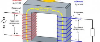
In power transformers, the tangent of the angle is calculated as the dielectric of the capacitor. The angle taken into account is the one that complements the right angle, the main angle between the phase shifts of current and voltage.
The angle located inside these planes is the desired dielectric loss.
For measurement, it is assumed that the capacitor is of an ideal type. It can be connected in series, that is, in series with a resistive load resistance, or in parallel. For the first, the power will be Р=(U2ωtgδ)/(1+tg2δ), and for the second - Р=U2ωtgδ. It is not difficult to calculate the angle according to these calculations, knowing the capacitance of the capacitor and resistance indicators. Usually its value does not exceed tenths or hundredths of a unit and is determined in graphs as percentages.
At the same time, they increase if the voltage and operating frequency increase. To reduce the coefficient, insulating materials are used.
What are dielectric losses?
The use of electrical insulating materials is based on the fact that they prevent electric current from traveling through a certain space limited by the insulator. An ideal insulator should absolutely exclude conditions for the conduction of electric current. Unfortunately, such materials do not exist in nature. Such dielectrics also could not be created in laboratory conditions.
Theoretically, it is possible to justify the existence of ideal insulators, but in practice it is not possible to synthesize such substances, since even a negligible fraction of impurities forms the dielectric constant. In other words, energy dissipation in a dielectric medium will always be observed. We can talk about efforts aimed at reducing such losses.
Based on the fact that part of the electricity is inevitably lost in the insulator, the term “dielectric losses” was introduced - the irreversible process of converting the energy of the electric field penetrating the dielectric medium into heat, that is, this is the electrical power aimed at heating the insulating material located in the action zone electric field.
The loss value is defined as the ratio of active power to reactive power. Typically, the active power consumed by a dielectric is very small compared to the reactive power. This means that the desired value will also be tiny - hundredths of a unit. For calculations, use the “tangent of the angle” value, expressed as a percentage.
The electrical characteristic expressing the dissipative property of the dielectric is called the dielectric loss tangent. In calculations, it is generally accepted that the dielectric is the insulating material of the capacitor, changing the capacitance and complementing the phase angle φ formed by the voltage and current vectors in the circuit up to 90º. This angle is denoted by the symbol δ and is called the dispersion angle, that is, dielectric loss. The value is numerically equal to the tangent of a given angle ( tgδ ), this is the very characteristic of dielectric heating.
tgδ is used in calculations to determine the amount of power dissipation using the appropriate formula. Therefore, its calculation is of practical importance. The introduction of the concept of tangent angle allows one to calculate the relative values of dielectric losses. And this allows you to compare the quality of different insulators.
It is this indicator or simply the angle δ that manufacturers of transformer oils indicate on the packaging of their products. The value of the angle (tg δ) can be used to judge the quality of the insulator: the smaller the angle δ, the higher the dielectric properties of the insulating material.
What contributes to increased dielectric losses
The norm of dielectric losses is prescribed in the instructions for a particular device. There are factors that cause fluctuations and deviations from the norm (usually an increase). There are several types:
- due to through-type electrical conductivity;
- ionizing;
- resonant;
- caused by polarization.
If the frequency and temperature dependence graph is intuitive, then the situation is different with other factors leading to a negative phenomenon. Please note that heating the transformer oil leads to a more intense displacement, sometimes even displacing the dielectric charges. At stable low temperatures, the viscosity does not change, therefore, there is no dipole shift.
But an increase in frequency causes improved conductivity. Indicators of capacitive current can shift dipoles; at higher values, friction decreases. An increase in the angle also causes the appearance of moisture in any form (it can also be a gaseous state). Ionization leads to an increase in the indicator, and the increase in voltage increases.
Dielectric Loss Measurement
Measuring dielectric losses involves a rather complex calculation system consisting of several actions.
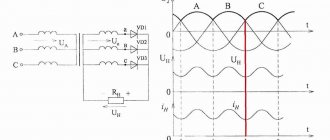
First of all, the power that is dissipated in the dielectric at alternating voltage is calculated. It is equal to the product of the voltage acting on it and the current that passes through the dielectrics (U and la, respectively).
Pa = U·Iа
If you refer to the dielectric equivalent circuit, you will see that it consists of a capacitor and an active resistance, which are connected in series.
Using the formula, we can calculate the active current passing through the dielectric; it will be the product of the tangent of the angle from the vector of the total current value to its capacitance lc (δ, respectively). Δ is also called the dielectric loss angle (or simply loss).
Ia = Ic•tgδ
Based on this, we can present a more detailed formula for calculating power as follows.
Pa = U•Ic•tgδ
If we take the value of the current different from the following expression (the letter C denotes the value of the capacitance of the capacitor, ω is the angular frequency).
Ic = U•ω•C
Ultimately, we get a much more detailed formula for calculating the power in a dielectric.
Pa = U2•ω•C•tgδ
From this formula we can already draw some conclusions. So, we see that the value of energy losses is in direct proportion to the dielectric loss tangent. In turn, the quality level of our dielectric depends on the value of this angle. To summarize, as the angle decreases, the level of dielectric properties of the substance increases. And the value of this angle allows you to express dielectric losses quantitatively and compare them with each other for different dielectrics.
Factors that increase the dielectric loss tangent
Experts identify several factors that lead to an increase in the tangent. At first glance, they seem insignificant, but ultimately they determine the efficiency of the transformer.
Presence of soap in oils
Soap in oils that are used to lubricate transformer windings leads to a change in the numerical indicator. This is explained by the fact that soap provokes additional moisture, leading to a decrease in resistivity. Nuances increase conductivity, which affects the growth of tangent.
Formation of acidic aging products
Acidic aging products cause damage to the secondary and primary windings. In turn, conductivity decreases and additions are formed on the crystal lattices. A change in the physical and technical characteristics of the dielectric for the worse leads to an increase in losses.
One of the most important tasks when using transport is to reduce the angle. This will optimize work and avoid wasting energy when idle.
Basic definitions.
A dielectric sample with losses can be presented in the form of an equivalent series (Fig. 1, a) or parallel (Fig. 1, b) circuit.
Rice. 1. Equivalent circuit and vector diagrams of a sample of insulating material:
a - sequential; b - parallel
Regardless of the choice of equivalent circuit (equivalent circuit), a number of parameters characterizing it remain unchanged. These include the phase shift δ between the current I in the unbranched part of the circuit and the voltage drop U throughout the entire circuit, the values of this current I and voltage U, dielectric losses P. Taking advantage of this circumstance, it is possible to derive relationships between the equivalent values of capacitance and resistance of both circuits .
For a series equivalent circuit, the following relations are valid:
For a parallel circuit:
From these expressions we obtain the ratios of the parameters of equivalent circuits [1]:
The quality of the insulation is judged by the value of the dielectric loss tangent of the insulation and its dependence on the applied voltage. As the voltage increases, dielectric losses in air voids and under-cured areas of insulation increase. Measuring the dielectric loss tangent reveals the presence of an unacceptable amount of air voids and/or under-cured insulation.
Method and scheme for measuring the dielectric loss tangent of insulation.
The dielectric loss tangent of insulation is measured in accordance with the requirements of the relevant standards for a specific product (cables, electrical machines, transformers).
For reproducibility of results, a “rest” interval of at least 2 hours is required between previous tests and the measurement of the dielectric loss tangent.
The tgδ measurement is carried out using an AC bridge. The schematic diagram of measuring the dielectric loss tangent is shown in Fig. 2.
Necessary equipment for measuring dielectric loss tangent:
- AC bridge;
- high voltage installation;
- reference capacitor.
Rice. 2. Schematic diagram of measuring the dielectric loss tangent of insulation.
C0 – reference capacitor;
IZ/NI – null indicator;
C1 – container store;
R1 – reference resistance;
R2 – resistance store;
A/V switch position – for measuring ungrounded/grounded products.
A schematic diagram of the arrangement of electrodes when measuring the dielectric loss tangent is shown in Fig. 3. The measuring electrode is made of metal foil, which ensures contact with the insulation surface. The length of the measuring electrode should be as long as possible. Security rings made of metal foil are located on the surface of the insulation. The width of the guard rings must be at least 10 mm. The distance along the insulation surface between the guard rings and the measuring electrode should be as small as possible, but not allow electrical contact between them, and should not exceed 4 mm.
Rice. 3. Schematic diagram of the arrangement of electrodes when measuring the dielectric loss tangent of insulation.
Measurement of the dielectric loss tangent of insulation is carried out at alternating voltage.
It is necessary to connect the high-voltage installation to the product being measured in accordance with Fig. 2.
The dielectric loss tangent is measured at voltages from 0.2UН to UNH, at intervals of 0.2UН, where UН is the rated voltage of the product.
The time between measurements when the voltage is raised is fixed; for repeated measurements, the time intervals must be observed.
Note: In the case of automated measurement, the time for reading the tgδ(U) dependence must be at least 15 s.
After the measurement, the voltage raising handle of the high-voltage installation returns to the zero position. After each power outage, the product under test should be discharged by electrically connecting it to ground for at least 5 minutes. The measuring capacitor must also be discharged.
The test result is the value of the dielectric loss tangent at 0.2UH, its change ∆tgδ in the range from 0.2UH to 0.6UH and the maximum value of ∆tgδ in the range of 0.2UH from the entire measured voltage range. A graph tgδ=f(U) is constructed.
The values of the measured quantities must not exceed the values specified in the relevant standards for a specific product. The increase in dielectric loss tangent with increasing voltage should not be sharp.
Literature:
1. Handbook of electrical materials / ed. Koritsky Yu.V., Pasynkova V.V., Tareeva B.M. – M.: Energoatomizdat, vol. 2, 1987. – 464 p.
You may also be interested in:
- Insulation moisture assessment
- Insulation resistance measurement
Schemes for all occasions
When a source of electrical energy is connected to a capacitor, part of it is lost in the form of heat (due to through conduction, energy consumption for displacement of charges during polarization, energy losses in leads and electrodes, losses due to ionization of air inclusions in the dielectric, etc.). If we compare the process of accumulating the charge of a capacitor with the accumulation of potential energy by a mechanical spring during its compression, then the energy losses in the capacitor should be compared with the energy losses in the spring, which are also released in the form of heat.
The amount of losses in a capacitor is estimated by the loss tangent δ, which complements up to 90° the phase angle between the current and voltage in the capacitive circuit. The loss tangent can also be expressed as the ratio of the active power loss of a capacitor to its reactive power at a sinusoidal voltage. Losses in a capacitor are primarily determined by the structure of its dielectric and the presence of various defects (foreign inclusions, increased conductivity, etc.). Vacuum capacitors have the lowest losses (tgδ≤10-5), aluminum electrolytic capacitors have the highest (tgδ=0.1-0.3).
In some cases, the determining factor in the value of tgδ is the resistance of the metal parts of the capacitor, especially at high frequencies due to the displacement of current to the surface of the conductor (skin effect), and for electrolytic capacitors - the resistance of the electrolyte.
Sometimes, to estimate losses in a capacitor, they use the reciprocal of tgδ, called the quality factor or power factor of the capacitor.
Measuring the loss tangent due to the complex nature of this quantity requires special care. Extension wires, poor contacts, and the presence of stray electric fields can significantly distort measurement results. The loss tangent of capacitors must be measured at the voltage and frequency values specified in the specifications using a measuring device with the error specified in the technical specifications for capacitors.
The loss tangent of electrolytic capacitors is measured at the value of the polarizing DC voltage specified in the specifications.
Capacitance measurements must be carried out at the voltage and frequency values specified in the current specifications using measuring instruments with an error 3-5 times less than the permissible deviation of the capacitance from the nominal value. The capacitor for measurement is connected directly to the device using the devices provided for the device - blocks with contact jaws or clamps with copper wires.
The design of the blocks or the length of the wires must be such that the additional error introduced does not exceed 10% of the permissible deviation of the capacitance. The capacitor lead, connected to the housing or to an external electrode (for ceramic capacitors), is connected to the grounded terminal of the measuring instrument or to a terminal with a lower potential relative to ground.
The series capacitance of electrolytic capacitors is measured using the bridge method at a DC polarizing voltage. The polarizing voltage values are indicated in the specifications.
When assessing the deviation of the capacitance from the nominal value, it should be taken into account that the actual deviation may differ from the measured one due to the instrument error.
When assessing the change in capacitance as a result of the influence of various factors on the capacitor (temperature, humidity, vibration, etc.), it should be taken into account that the actual change in capacitance may differ from the measured one by twice the instrument error.
List of used literature
- Elements of radio-electronic equipment. Electric capacitors of constant capacity. V.N. Gusev, V.F. Smirnov. - M.: Soviet radio, 1968.