Design and principle of operation
The appearance of a typical current transformer is shown in Figure 1. A characteristic feature of these models is the presence of a dielectric housing. Case shapes can be different - from rectangular to cylindrical. Some designs do not have pass-through bars in the center of the body. Instead, a hole was made to wrap around the wire, which serves as the primary winding.
Rice. 1. Current transformer
Dielectric materials are selected depending on the voltage for which the device is intended and on its operating conditions. To service industrial energy systems, powerful CTs with cylindrical ceramic housings are manufactured (see Fig. 2).
Rice. 2. Industrial ceramic current transformer
A feature of the transformer is the mandatory presence of a load element (resistance) in the secondary winding (see Fig. 3). The resistor is necessary in order to prevent operation in mode without secondary loads. The operation of a current transformer with unloaded secondary windings is unacceptable due to strong heating (up to destruction) of the magnetic circuit.
Rice. 3. Schematic diagram of a current transformer
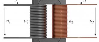
Unlike voltage transformers, CTs are equipped with only one turn of the primary winding (see Fig. 4). This turn is often a busbar passing through a core ring with secondary windings wound on it (see Fig. 5).
Rice. 4. Schematic representation of the CT
Rice. 5. CT device
Sometimes the conductor of an electrical circuit acts as the primary winding. To do this, the core design allows the use of a hinged connection of the transformer parts to wrap around the wire (see Fig. 6).
Rice. 6. TT with split housing
Transformer cores are made by fusion of silicon steel. In high-precision models, the cores are made from materials based on nanocrystalline alloys.
Operating principle.
The main task of current transformers is to lower (increase) the current value to an acceptable value. The operating principle is based on the transformation properties of alternating electric current. The resulting alternating magnetic flux is captured by a magnetic core perpendicular to the direction of the primary current. This flux is created by the alternating current of the primary coil and induces an emf in the secondary winding. After connecting the load, electric current begins to flow through the secondary circuit.
The relationships between windings and currents are expressed by the formula: k = W2 / W1 = I1 / I2.
Since the current in the secondary coil is inversely proportional to the number of turns in it, by increasing (decreasing) the transformation ratio, depending on the ratio of the number of turns in the windings, the desired output current can be achieved.
In practice, most often, this value is set by selecting the number of turns in the secondary winding, making the primary winding single-turn.
The linear dependence of the output current (at rated power) allows you to determine the parameters of quantities in the primary circuit. Numerically, this value in the secondary coil is equal to the product of the real current value and the rated transformation ratio.
Ideally, I1 = kI2 = I2W2/W1 . Taking into account the fact that W1 = 1 (one turn) I1 = I2W2 = kI2 . These simple calculations can be included in the electronic meter program.
Rice. 7. Operating principle of the current transformer
Figure 7 does not show the load resistor. When measuring, its influence must also be taken into account. All permissible errors in measurements are reflected by the TT accuracy class.
Purpose of the device
According to their purpose, current transformers belong to special auxiliary devices used in conjunction with various measuring equipment and protective mechanisms in alternating current networks.
The principle of operation of a current transformer is the transformation of any quantities that acquire more perceivable values to obtain information and provide power to protective relays. Thanks to the insulation of the devices, the employees of the service organization are reliably protected from electric shock. All types of transformers can serve two functions:
- Measuring current in a circuit - with their help, data is transmitted to measuring instruments that are connected to the secondary winding. In this case, the transformer can convert the high current into more acceptable parameters.
- Safety actions - devices primarily transmit data to protective devices and control devices. With the help of transformers, electrical indicators are converted to power relay equipment.
According to their purpose and principle of operation, current transformers facilitate the connection of measuring instruments to high-voltage power lines when it is not possible to connect them directly. They are needed to transmit the readings taken to the measuring equipment, which is connected to the secondary winding.
In addition, converters monitor the state of the electrical current in the circuit to which they are connected. When connected to automatic power protection, the device monitors networks, the presence and condition of grounding. If the current reaches the maximum value, the protection is automatically activated and the operation of all equipment is stopped.
Classification
The family of current transformers is classified according to several criteria.
- By purpose:
- protective;
- lines of measuring current transformers;
- intermediate (used to equalize currents in differential protection systems);
- laboratory
- By installation method:
- external (see Fig. 8), used in outdoor switchgear;
- internal (located in the closed switchgear);
- built-in;
- overhead (often combined with bushings);
- portable.
Rice. 8. Example of outdoor use of TT
- Classification according to the type of primary winding: multi-turn, which includes coil structures, and transformers, with windings in the form of loops;
- single-turn;
- tire
- Up to 1 kV;
- Over 1 kV.
Current transformers can be classified according to other criteria, for example, by type of insulation or by the number of transformation stages.
Design Features
What are these transformers made of? What is the difference between a current transformer and a voltage transformer? The answers to these questions can be found in the description of the design features. Current transformers, their purpose and principle of operation, imply the constancy of certain conditions:
- every CT must have more than one winding on its magnetic core;
- windings that are secondary are certainly connected to the load (Rн);
- resistance Rн should not contain deviations from the TT stated in the documents;
- The primary winding is made as a busbar passing through the core or in the form of a coil.
What is a diode - operating principle and device
The absence of a load on the secondary winding does not ensure the occurrence of magnetic flux F2 in the core, which has a compensating property. This leads to an increase in the temperature of the core and its melting. Heating occurs because F1 becomes too high.
Resistance deviation Rн affects the measurement error and worsens it. If the resistance in the secondary winding is exceeded, the voltage U2 increases and the CT insulation may fail. A breakdown will occur and the device will fail.
Information. Voltage transformers (VTs) differ from CTs in their method of application and connection diagram. They are connected in parallel and are designed to increase or decrease the voltage, decoupling the power circuit from the control and monitoring circuit. The main operating regulations of the fuel pump are close to the idle mode (idle). This is due to the fact that parallel-connected elements of the control circuit consume low current, and their Rн is large.
Classic TT device
Explanation of markings
Each type of transformer is assigned alphanumeric symbols, by which its main parameters can be determined:
- T - current transformer;
- P is a letter indicating that we have a pass-through transformer. The absence of the letter P indicates that the device belongs to the class of reference CTs;
- B - indicates that the transformer is built into the structure of the oil switch or into the mechanism of another device;
- VT - built into the design of the power transformer;
- L—with resin (cast) insulation;
- FZ is a device in a porcelain case. Link type of primary winding;
- F - with reliable porcelain insulation;
- Ш - tire;
- O - single-turn;
- M - small-sized;
- K - reel;
- 3 - used for protection against the consequences of a ground fault;
- U - reinforced;
- N - for outdoor installation;
- R - with a core intended for relay protection;
- D - with a secondary coil designed to supply electricity to differential protection devices;
- M - oil-filled. Used for outdoor installation.
- The rated voltage (in kV) is indicated after the letter symbols (first digit).
- Numbers separated by a fraction indicate the accuracy classes of the cores. Some manufacturers put the letters P or D instead of numbers.
- the next two digits “separated by a fraction” indicate the parameters of the primary and secondary currents;
- after the position of fractional symbols - the code of the design option;
- letters located after the design option code indicate the type of climate control;
- The number in the last position is the placement category.
How the device works
When it became clear what transformation is, it’s time to take a closer look at the operating principle of the current transformer.
Connecting the current transformer
Two windings are placed on a closed core (magnetic circuit) assembled from plates. The first coil is connected in series to the load power circuit. The secondary coil is connected to the meters with its terminals. The core is assembled from cold-rolled silicon steel plates.
For your information. Electricity metering is done in exactly this way. Current transformers are included in single-phase and three-phase circuits, which allow readings to be taken for each phase, feeding data to the meter.
When alternating electricity passes through the turns of the first (main) winding, an alternating magnetic flux F1 is formed around it. Flow F1, penetrating all windings of the transformer, induces EMF (E) in them. In this case, E1 and E2 appear. When any load is connected to the secondary winding circuit, electricity will begin to flow through it.
Operating principle of TT
Connection diagrams
The primary coils of current transformers are connected in series in the circuit. Secondary coils are designed to connect measuring instruments or are used in relay protection systems.
The secondary circuit includes the terminals of measuring instruments and relay protection devices. To ensure safety, the magnetic core and one of the secondary coil terminals must be grounded.
When connecting three-phase meters, in networks with an isolated neutral, the transformer windings are connected according to the “Partial star” circuit. If there is a neutral wire, a full star circuit is used.
Transformer terminals are marked. For the primary winding, the designations L1 and L2 are used, and for the secondary winding - I1 and I2. When connecting measuring instruments, the polarity of the windings must be observed.
The "partial star" circuit is used for a two-phase connection.
In differential protection used in power transformers, the windings are connected in a delta.
Basic connection diagrams:
Basic connection diagrams
- In networks with a solidly grounded neutral, the CT is connected to each phase. The connection of the transformer windings is a full star.
- Connection according to a partial star circuit. Used in networks with isolated zero points.
- Eight diagram. Symmetrically distributes loads during a three-phase short circuit.
- CT connection to a zero-sequence current filter. Used to protect the rated load from short circuits to ground.
Popular models
Any manufactured brand of device has individual parameters and technical characteristics. Domestic manufacturers produce a large number of these devices. These include:
- TOL-NTZ-10−01 - produced by Nevsky Transformer and is used to transmit readings to measuring equipment. In addition, it is used in electrical circuits with protection and control devices. The converter is produced in the form of a support structure of the second placement category. The device is used in networks with voltages up to 10 kV and has a service life of up to 30 years.
- TOP-0.66 - used in AC power networks with voltages up to 0.66 kV. The device body is made of non-flammable material. Operation of the unit is possible in the temperature range from -45 to +50 °C and in any position. The primary busbar of the transformer consists of tin-plated copper.
- VV, VVO are feed-through busbar current transformers manufactured in a compound housing. The devices are used in AC networks with voltages up to 24 kV. They have a mechanical change in the transformation ratio on both windings.
You may be interested in this Definition of Ohm's law applied to a complete circuit
Three-phase devices are connected to the network in a "triangle" or "star". In the first case, it is possible to obtain a large current value in the secondary winding, and in the second, it is possible to track the current value in each phase.
Technical specifications
A very important characteristic of a current transformer is its accuracy class. This parameter characterizes the measurement error, that is, it shows how much the nominal (ideal) transformation ratio differs from the real one.
Transformation ratio
Since the real transformation ratio contains an in-phase and quadrature component, the coefficient values always differ from the nominal one. The difference (error) must be taken into account when measuring. Angular errors also affect the measurement results.
All CTs have a negative error, since they always have losses from magnetization and heating of the current coils. In order to eliminate the negative sign of the error, a turn correction is used to shift the transformation parameters in the positive direction. Therefore, in adjusted devices, the usual formula for calculations does not work. Therefore, manufacturers determine transformation ratios in such devices experimentally and indicate them in the technical passport.
Accuracy class
Current errors distort the accuracy of electrical current measurements. Therefore, for instrument transformers there are high requirements for the accuracy class:
- 0,1;
- 0,5;
- 1;
- 3;
- 10P.
A transformer can be within the declared accuracy class only if the maximum load resistance does not exceed the rated one, and the current in the primary circuit does not exceed the limits of 0.05 - 1.2 of the rated current of the transformer.
What is the difference between a current transformer and a voltage transformer and a power transformer?
There are differences in the operation of CT and.
- The primary current of the CT does not depend on the secondary load, which is typical for VTs. This is determined by the fact that the resistance of the secondary winding of the CT is an order of magnitude less than the resistance of the primary circuit and, in general, the closer it is to zero, the more accurate the device. In voltage transformers and power transformers, the primary current depends on the magnitude of the secondary load current.
- The CT always operates with a closed secondary winding and the value of its secondary load resistance does not change during operation.
- It is not allowed to operate a CT with an open secondary winding; for VT and power transformers, when the secondary winding is opened, a transition to idle operation occurs.
CT accuracy classes
MAIN PERFORMANCE CHARACTERISTICS
The scope of application of TT type converting devices is closely related to their basic parameters and technical design solutions. In accordance with GOST 7746-2015 (general technical conditions), the following key parameters are distinguished.
Rated voltage.
An indicator of the operating voltage value in the measured electrical network.
Rated current.
There are two types of this indicator for the primary and secondary circuit. They flow respectively through the primary and secondary windings of the device. In this case, the rated operating current is constant and equal to 1 or 5 A.
Secondary load.
An indicator of the total resistance of all external circuit devices connected to the secondary winding: electricity meters, ammeters, relay protection devices, and converters. The parameter is measured in ohms (Ohm).
Transformation coefficient.
The ratio of primary and secondary current indicators. This parameter is usually divided into nominal and real (real).
Electrodynamic resistance.
Expressed as the maximum amplitude of electric current during a short circuit per unit of time (usually one second). The current transformer windings must withstand the specified value without breakdown or any other damage.
Electrodynamic resistance indicators do not apply to detachable, built-in or busbar CTs.
Heat resistance.
The maximum current value during a short circuit per unit of time (1 second), at which heating of the current-carrying parts of the transformer does not exceed critical temperatures and does not cause damage.
Classification of current transformers
The operating principle of the current transformer, as well as the methods of connection and purpose, allow them to be divided according to the following differences:
- purpose;
- type of installation;
- placement method;
- performing the primary winding;
- type of insulation;
- operating voltage;
- number of transformation steps.
In addition, there are other qualities that allow the classification of TT. One of the distinguishing features is the specificity of the design.
According to the design features, CTs differ in:
- single-turn;
- multi-turn;
- optical-electronic.
Each of these types has model types that it is advisable to consider separately.
Coil type CT
These are some of the simplest current transformers. They belong to early CTs, built and promoted on a structure based on a power transformer. Both windings (first and second) are mounted on a frame with insulating properties. Each of them is a coil. This is where the name comes from. In addition to the fact that they are compact and cheap to manufacture, there is a drawback: low discharge voltage due to poor insulation of the coils.
This design allows them to be used only for voltages up to 3 kV. To increase the value of Udispersion, it is necessary to increase the core window and separate the primary winding from the inner surface of the plates. An insulating gasket having a U-shaped form is inserted into the resulting gap.
Coil transformer
Pass-through transformer
Distribution devices (distribution devices) with voltages from 6 to 35 kV imply the installation of similar current transformers. This is a multi-turn CT, where the base is a pair of bushings connected to each other in the middle. This assembly allows them to pass through walls and be used in closed switchgears. In this case, there is no need to specifically use the bushing.
The winding, which serves as the primary winding, is laid through the void located inside. The number of turns is taken from the calculation of the required “ampere-turns” for the corresponding accuracy class. Bushings are placed under the flange, which is grounded. The magnetic cores of the secondary windings, covered with a casing, are fixed in their middle.
Attention! The location of the winding terminal for the primary winding is on the upper plane, relative to the grounded flange.
Pass-through high-voltage CT
Rod device
This type of device is designed to work with U = 10-20 kV and In = 600 and 1500 A. This CT refers to feed-through single-turn transformers with porcelain insulation. It has a current-carrying rod piercing a porcelain insulator and serves as the primary winding.
Rod current transformer
Tire device
The following design is intended for installation in complete transformer substations (CTS). They implement the transfer of measurement information to control and measuring instruments (instruments). Signals from similar CTs are also transmitted to protection and control circuits.
Bus TT type TSHL-0.66-1
Advantages and disadvantages
Each of the listed devices has its own pros and cons. It is preferable to consider them separately: single-turn and multi-turn models.
The advantages of single-turn CTs include:
- simplicity of the device;
- low cost;
- small dimensions;
- resistance to short circuit currents (short circuit).
Here we can add that by changing the cross-section of the current conductor (rod), we achieve a change in thermal stability.
The disadvantage of such models is their low accuracy at low measured currents.
As for multi-turn models, a clear positive point is the presence of a certain number of turns in the primary winding. This made it possible to significantly increase the measurement accuracy class. Negative characteristics include:
- design complexity;
- rise in price;
- susceptibility of the primary winding to interturn overvoltages.
At the same time, this also includes low resistance to short-circuit currents.