Wireless radio waves
When the need for wireless communication arises, an antenna is needed. It has the ability to send or receive electromagnetic waves for communication where a wired system cannot be installed.
The antenna is the key element of this wireless technology. Radio waves are easily created and are widely used for both indoor and outdoor communications due to their ability to pass through buildings and travel long distances.
Key features of transmitting antennas:
- Since radio transmission is omnidirectional, there is no need for physical matching between the transmitter and receiver.
- The frequency of radio waves determines many transmission characteristics.
- At low frequencies, waves can easily pass through obstacles. However, their power decreases with the inverse square of distance.
- Higher frequency waves are more likely to be absorbed and reflected by obstacles. Due to the long transmission range of radio waves, interference between transmissions is a problem.
- In the VLF, LF and MF bands, the propagation of waves, also called ground waves, follows the curvature of the Earth.
- The maximum transmission ranges of these waves are on the order of several hundred kilometers.
- Transmit antennas are used for low-bandwidth transmissions such as amplitude modulation (AM) radio transmission.
- HF and VHF transmissions are absorbed by the atmosphere close to the Earth's surface. However, part of the radiation, called the sky wave, travels outward and upward to the ionosphere in the upper atmosphere. The ionosphere contains ionized particles formed by radiation from the Sun. These ionized particles reflect sky waves back to Earth.
Wave Propagation
- Line of sight propagation. Among all the distribution methods, this is the most common. The wave travels the minimum distance that can be seen with the naked eye. Next, you need to use an amplifier transmitter to increase the signal and transmit it again. Such propagation will not be smooth if there is any obstacle in its transmission path. This transmission is used for infrared or microwave transmissions.
- Ground wave propagation from a transmitting antenna. The wave propagates to the ground along the contour of the Earth. Such a wave is called a direct wave. The wave sometimes bends due to the Earth's magnetic field and hits the receiver. Such a wave can be called a reflected wave.
- A wave propagating through the earth's atmosphere is known as a terrestrial wave. The direct wave and the reflected wave together produce a signal at the receiving station. When the wave reaches the receiver, the delay stops. Additionally, the signal is filtered to avoid distortion and amplification for clear output. The waves are transmitted from one place and where they are received by many transceiver antennas.
Do I need to lock the shield?
The door of the switchgear housing must move without jamming and open freely at an angle of more than 95°, but not less. Access to internal electrical equipment should be convenient both during hardware installation and during maintenance.
Apartment panels with automatic circuit breakers (automatic switches) can be produced by the manufacturer without doors, if this is agreed with the consumer.
The operating panel with the output of the control elements is located behind the door and blocks access to internal live parts.
The doors of apartment and floor distribution devices must be locked with a key. If the panel is located in an apartment and is equipped with automatic machines, then locking is not necessary.
At the request of the consumer, additional hatches with lockable doors and access to the control elements of the equipment separately for all apartments on the floor are made in floor distribution devices (metering, group).
If there are no doors in an apartment panel equipped with automatic switches, the operating panel must be resistant to mechanical damage and impacts applied with a force of 0.7 J.
Doors that cannot be locked with a key are equipped with devices that prevent accidental opening.
Low-current devices that are located in a separate compartment of the distribution panel behind a metal partition must be shielded. In addition, a metal partition, whose thickness is indicated in the design documentation, also serves as fire protection. This compartment is equipped with a separate key-locked door.
To prevent unauthorized access to electricity meters, apartment and floor switchgears are equipped with design elements that can be sealed. In shields located on the floor, seals are placed on the doors.
Switchgears in which meters are installed are equipped with transparent windows located above them, the material for the manufacture of which must be impact-resistant.
Antenna measurement coordinate system
When looking at flat models, the user will be faced with the azimuth of the plane and the height of the pattern plane. The term azimuth usually occurs in reference to the "horizon" or "horizontal", while the term "elevation" usually refers to the "vertical". In the figure, the xy plane is the azimuthal plane.
The azimuthal plane pattern is measured when the measurement is made by moving the entire xy plane around the transceiver antenna under test. An elevation plane is a plane orthogonal to the xy plane, such as the yz plane. The elevation plane plan traverses the entire yz plane around the antenna under test.
Patterns (azimuths and elevation plots) are often displayed as polar plots. This allows the user to easily visualize how the antenna radiates in all directions, as if it were already "targeted" or mounted. It is sometimes useful to draw radiation patterns in Cartesian coordinates, especially when there are multiple sidelobes in the patterns and where sidelobe levels are important.
Basic communication characteristics
Antennas are the main components of any electrical circuit because they provide the coupling between a transmitter and free space or between free space and a receiver. Before talking about antenna types, you need to know their properties.
An antenna array is a systematic deployment of antennas that work together. The individual antennas in an array are usually of the same type and are located in close proximity, at a fixed distance from each other. The array allows for increased directivity, control of the main radiation beams and side beams.
All antennas are characterized by passive gain. Passive gain is measured by dBi, which is related to a theoretical isotropic antenna. It is believed to transmit energy equally in all directions, but does not exist in nature. The gain of an ideal half-wave dipole antenna is 2.15 dBi.
EIRP, or equivalent isotropic radiated power of a transmitting antenna, is a measure of the maximum power that a theoretical isotropic antenna would radiate in the direction of maximum gain. EIRP takes into account losses from power lines and connectors and includes actual gain. EIRP allows real power and field strength values to be calculated if the actual gain and output power of the transmitter are known.
Terminology
GOST R 51628-2000 contains:
| Term | Definition |
| Apartment shield | |
| Group | Located in the apartment, used to connect a group of lines, the meter is located on the floor in the metering and distribution panel (URS) |
| Accounting-group | The meter is inside the switchboard, the device is located in the apartment |
| Floor panel | |
| Distribution | Serves to connect group devices located in apartments on this floor |
| Accounting and distribution | Using this panel, electricity supplied to apartments located on the floor is taken into account and distributed |
| Combined | With an additional compartment for low-current networks (for connecting a telephone, radio and television receivers, the Internet) |
| Chain | |
| Nourishing | From input to floor panel |
| Distribution | From floor to apartment units |
| Group | From the panel to the lines of electrical receivers - lighting devices, sockets, etc. |
Antenna gain in directions
It is defined as the ratio of the power gain in a given direction to the power gain of the reference antenna in the same direction. It is standard practice to use an isotropic radiator as the reference antenna. In this case, an isotropic emitter will be lossless and radiate its energy equally in all directions. This means that the gain of an isotropic radiator is G = 1 (or 0 dB). It is common practice to use a dBi (decibels relative to an isotropic driver) block for gain relative to an isotropic driver.
The gain, expressed in dBi, is calculated using the following formula: GdBi = 10 * Log (GNumeric / GIsotropic) = 10 * Log (GNumeric).
Sometimes a theoretical dipole is used as a reference, so the unit dBd (decibels relative to dipole) will be used to describe the gain relative to the dipole. This block is typically used when it comes to amplifying higher gain omnidirectional antennas. In this case, their gain is 2.2 dBi higher. Therefore, if the antenna has a gain of 3 dBc, the total gain will be 5.2 dBi.
Design
When operating switchboards, they are affected by heat, electricity, and possible mechanical damage, so they are made from materials that are resistant to these factors.
Material requirements
Class I devices in terms of the degree of protection against electric shock are made of metal, but it is possible to supplement them with other materials.
The housings or shells of class II products are made of slightly or moderately flammable materials that are resistant to ignition and, in terms of flammability, belong to the B1 group. Such shields are installed on/in non-combustible walls.
The insulating elements of devices of classes I and II, to which live parts are attached, must comply with GOST R 51321.3 in terms of resistance to ignition. Requirements for the heat resistance of class II housings or shells are specified in the same standard.
The material from which the shells of the two classes of shields are made is selected with resistance to impacts and other mechanical impacts with a force of 0.7 J, and class I housings must also be corrosion-resistant.
Design features
The housings or shells of the panels are made in the form of cabinets or drawers that are hung on the wall.
The housing component can only be removed if you use a special tool.
The strength of screw fasteners when installing removable elements is in accordance with the requirements of GOST R 51321.3.
You need to know to install the shield: regardless of the installation method - hanging or embedding in a niche, the shields are equipped with elements with which they are attached to the wall surface.
Apartment and floor-type devices that are built into a niche are framed with structures that cover the protruding edges of the wall.
All electrical elements located inside the panels must be placed in such a way that it is possible to freely insert external cables and connect devices to switching terminals.
Beam width 3 dB
This beamwidth (or half power beamwidth) of the antenna is usually determined for each of the principal planes. The 3 dB beamwidth in each plane is defined as the angle between the main lobe points that are reduced from the maximum gain by 3 dB. The 3 dB beamwidth is the angle between the two blue lines at the polar site. In this example, the 3 dB beam width in this plane is about 37 degrees. Wide beamwidth antennas typically have low gain, while narrow beamwidth antennas have higher gain.
Thus, an antenna that directs most of its energy into a narrow beam in at least one plane will have higher gain. The forward-to-backward (F/B) ratio is used as a merit metric that attempts to describe the level of radiation from the back of a directional antenna. Basically, the front-to-back ratio is the ratio of the peak gain in the forward direction to the gain 180 degrees behind the peak. Of course, on a DB scale, the front-to-back ratio is simply the difference between the peak gain in the forward direction and the gain 180 degrees behind the peak.
Antenna classification
There are many types of antennas for different applications such as communications, radar, measurement, emulation of electromagnetic pulse (EMP), electromagnetic compatibility (EMC), etc. Some are designed to operate in narrow frequency bands, while others are designed to to emit/receive transient pulses. Characteristics of transmitting antennas:
- Physical structure of the antenna.
- Operating frequency ranges.
- Application mode.
Below are the types of antennas according to physical structure:
- wire;
- aperture;
- reflective;
- lens antennas;
- microstrip antennas;
- massive antennas.
Below are the types of transmitting antennas depending on the frequency of operation:
- Very Low Frequency (VLF).
- Low frequency (LF).
- Mid Frequency (MF).
- High frequency (HF).
- Very high frequency (VHF).
- Ultra high frequency (UHF).
- Super High Frequency (SHF).
- Microwave wave.
- Radio wave.
The following are the transmitting and receiving antennas according to application modes:
- Point-to-point communication.
- Broadcasting applications.
- Radar communications.
- Satellite connection.
Television antenna for digital TV
To watch digital terrestrial television, in addition to the DVB T2 set-top box, you also need an antenna. There is an opinion that antenna is needed for digital TV , with unusual shapes and special characteristics. Actually this is not true. The carrier frequencies of digital multiplexes have values in Moscow of about 500 MHz, at the beginning of the UHF decimeter range, the same nature and form as the usual electromagnetic waves of analogue television. Digital TV signals will be successfully received by a regular decimeter television antenna. In difficult terrain conditions and a large distance from the television center, a decimeter directional antenna with an amplifier should be used. At a short distance from the transmitting television tower, you can use a passive UHF antenna without an amplifier. The “Locus” antenna and “Delta antenna” have proven themselves well; active or passive “room antennas” are also applicable.
Moreover, practice shows that an antenna for digital television can be simpler, with worse characteristics and smaller in size than an antenna for stable reception in the same place of analog television in the UHF UHF range. You can also successfully use homemade antennas.
Homemade TV antenna
Simple homemade antennas have always been used to watch TV. However, in most specific cases, they were noticeably less effective compared to geometrically adjusted factory-made antennas. With the advent of the era of digital terrestrial television, the use of a homemade antenna for digital TV is often justified. A homemade TV antenna can be made from any available materials. You can often find home-made antennas made from cleaned electrodes, copper-plated tractor gaskets, thick copper wire, etc. The main thing is two identical conductive parts so that the antenna is symmetrical, a television cable with a plug, and a stand for mounting. We assemble, install, configure, that is, rotate it in different directions and watch TV.
Homemade TV antennas for digital TV
The most commonly used types of antennas for digital television are:
- Whip TV antenna - an antenna plug is put on a piece of antenna cable 10 - 25 cm long, and the second end of the cable is cleared of external insulation, a layer of foil and metal braiding. At a distance of 2 cm from the plug, the antenna is bent and inserted into the TV. The antenna can be installed vertically or horizontally.
- A T-shaped TV antenna is a type of whip antenna in which the braid removed from the cable is not removed, as in a whip antenna, but forms a symmetrical wave vibrator together with the central conductor.
- Antenna for digital TV Figure Eight - from a piece of wire about 1 m long, a piece of antenna cable is also suitable, the figure eight is folded so that there is no connection in the center, but a gap of 1 cm is obtained. At these points of the separated connection, the antenna cable, braid and central one are attached in any way conductor. A TV antenna made in this way can be mounted on a cardboard shoe box, and metal foil can be glued to the opposite wall - a kind of reflector.
- Antenna for digital television Cans—two metal cans of juice, cola, or beer are attached to a wooden stick or wooden hanger at a distance of several centimeters. Holes are made in the cans into which the braid and conductor of the antenna cable are inserted.
The effectiveness of homemade television antennas
Observing a wide variety of designs of television antennas made by hand, it is easy to conclude that all of them, in one way or another, repeat the design of the symmetrical half-wave vibrator described above, only made incorrectly. Therefore, we can unequivocally say that besides a funny appearance, a homemade television antenna has no other advantages. If such an antenna is installed outside and raised high, then its “satisfactory” operation is determined only by a good location, and a simple vibrator in this place would be even more effective. If a homemade television antenna is used as an indoor antenna, then its performance can be compared to a piece of soft wire inserted into the antenna input of the TV. Such a wire can be fixed to the window, bent in the optimal way, and make sure that its receiving properties are no less effective.
Design features
Transmitting antennas produce radio frequency radiation that travels through space. Receiving antennas perform the reverse process: they receive radio frequency radiation and convert them into the required signals, for example, sound, image in television transmitting antennas and mobile phones.
The simplest type of antenna consists of two metal rods and is known as a dipole. One of the most common types is the monopole antenna, which consists of a rod placed vertically against a large metal board that serves as a ground plane. The installation on vehicles is usually a monopole, with the metal roof of the vehicle serving as the ground. The design of the transmitting antenna, its shape and size determine the operating frequency and other radiation characteristics.
One of the important attributes of an antenna is its directivity. Communication between two fixed targets, as in communication between two fixed transmitting stations, or in radar applications, requires an antenna to directly transmit the transmit energy to the receiver. Conversely, when the transmitter or receiver is not fixed, as in cellular communications, an omnidirectional system is required. In such cases, an omnidirectional antenna is required, which uniformly receives all frequencies in all directions of the horizontal plane, and in the vertical plane the radiation is uneven and very small, like that of an HF transmitting antenna.
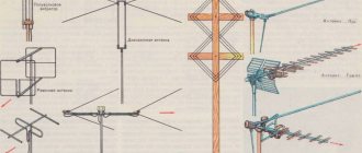
TYPES AND TYPES OF ANTENNAS
There are many known designs of radio antennas. The most successful of them became widespread.
The simplest and perhaps most common are the dipole and quarter-wave antenna. The first consists of two conductors about a quarter wavelength each; the second is made of a single conductor about a quarter of a wave long. A quarter-wave antenna is often called a "whip" antenna. The dipole and the “pin” are narrowband radio antennas with a gain of 2 - 5 dB.
A whip antenna equally emits/receives a signal in all directions in a plane perpendicular to its axis. There is no radiation along the axis. Such radio antennas are used if the relative position of the transmitting and receiving devices changes all the time. Therefore, “pins” can often be seen on cars, portable radios, walkie-talkies, and WiFi routers.
The simplicity of the design also facilitates its use in the case of relatively stationary objects: the famous “whisker” indoor television antenna is nothing more than a dipole. In order to mitigate the disadvantages associated with a narrow bandwidth, the “whiskers” are made telescopic, and they can be adjusted to the desired wavelength.
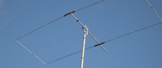
As outdoor TV antennas, you can often see a “wave channel” - a narrow-band directional radio antenna with a gain of 5 - 12 dB (depending on the modification). It was invented in 1926 by Shintaro Uda and Hidetsugu Yagi from Tohoku Imperial University (Japan). Yagi patented the invention, and a second name began to be used for the antenna - Yagi.
The design uses one active element (dipole) connected to the transmission line. Its size is comparable to half a wavelength. Passive elements are mounted on one rod with a dipole:
- reflector (longer than the dipole);
- director (in short, dipole).
The main reception (transmission) of the “wave channel” goes in the direction of the director. There may be several directors. The addition of each new element increases the gain and reduces the angle of action (increases directivity).
An alternative to the “wave channel” when receiving a television signal is a log-periodic antenna. It looks like a Yagi antenna, but it has a different configuration. This broadband radio antenna with a gain of 6 - 7 dB was invented in 1958 by Dwight Isbell and Raymond Duhamel at the University of Illinois (USA).
A log-periodic antenna consists of a number of active elements (dipoles), arranged in descending order of their length. Adding new elements increases the bandwidth. The peak of the radiation pattern is located on the side of the shorter dipole.
As for another popular design - a panel antenna (patch), it is most often used for WiFi, GSM, 3G, 4G, GPS. Such a narrowband directional radio antenna with a gain of 5 - 10 dB is a rectangular (sometimes elliptical) plate and a reflector plate (screen), separated by a dielectric layer.
The design became most widespread starting in the 70s of the 20th century, when panel antennas began to be widely used on printed circuit boards. The side length of a rectangular patch plate is comparable to half the wavelength if there is air or other material with a similar dielectric constant between the plate and the screen.
A parabolic antenna can be obtained from any antenna by placing it at the focus of a reflector. The “dish” makes an arbitrary antenna highly directional, increasing the gain to 30-40 dB. Scientists have at their disposal several giant reflectors with a gain of 80 dB, which are used as part of radio telescopes.
The bandwidth depends on the radio antenna placed in focus. Satellite dish is another name derived from its use for receiving satellite TV.
In order to make the bandwidth wider or to use several ranges in operation, combined designs are made - several in one. For example, outdoor Yagi TV antennas for decimeter waves, combined with a dipole for meter waves, are common.
Transmitting and receiving sources
The transmitting device is the main source of radio frequency radiation. This type consists of a conductor whose intensity fluctuates over time and converts it into radio frequency radiation that travels through space. A receiving antenna is a device for receiving radio frequencies (RF). It performs the reverse transmission performed by the transmitter, receives radio frequency radiation, converts it into electrical currents in the electrical circuit of the antenna.
Television and radio broadcast stations use transmitter antennas to transmit certain types of signals that travel through the air. These signals are detected by receiving antennas, which convert them into signals and are received by the corresponding device, for example, TV, radio, mobile phone.
Radio and television receiving antennas are designed solely to receive radio frequency energy, and they do not produce radio frequency energy. Cellular communications devices, such as base stations, repeaters, and mobile phones, are equipped with designated transmit and receive antennas that emit radio frequency radiation and operate cellular networks in accordance with communications network technologies.
Difference between analog and digital antenna:
- The analogue antenna has variable gain and operates over a range of 50 km for DVB-T. The further the user is from the signal source, the worse the signal.
- To receive digital TV, the user receives either a good image or no image at all. If it is far from the signal source, it does not receive any image.
- The digital transmitting antenna has built-in filters to reduce noise and improve image quality.
- An analog signal is sent directly to the TV, while a digital signal must first be decoded. This allows you to correct errors as well as data like signal compression to get additional features like additional channels, EPG, Pay TV, interactive games, etc.
How to set up an indoor antenna
As mentioned above, simple products with a rod structure work in the meter range, and frame ones in the decimeter range. For high-quality signal reception at a sufficient distance from the transmitting station, it is better to use combined devices equipped with an amplifier.
Setting up a TV antenna
- Place the product as close as possible to the TV receiver so that there is a window opening nearby.
- First you need to adjust the image to stations broadcasting in the meter range. You need to extend/push in, change the angle between the telescopic rods until a position with a good picture and sound is found.
- To search for a high-quality image and audio track in the UHF range, you need to rotate the frame.
- If the product is equipped with an amplifier, use the control to set the desired gain, again selecting the position that provides the best picture/sound.
Although television equipment is constantly being improved, many users successfully use simple household outdoor/indoor antennas, active or passive.
Whether to lock the distribution panel - about some safety aspects
https://electrotorg.ru/elektromontazhnoe-oborudovanie/raspredelitelnye-shchity-shkafy-upravleniya/
The rules for the manufacture and operation of distribution boards for various purposes and with different contents are listed in GOST R 51628-2000. This standard is intended for both newly constructed public or multi-apartment buildings and individual buildings, as well as for existing housing stock.
Dipole transmitters
Dipole antennas are the most common omnidirectional type and distribute radio frequency (RF) energy 360 degrees in the horizontal plane. These devices are designed to be resonant with one-half or one-quarter wavelength of the applied frequency. It can be as simple as two pieces of wire of the desired length, or it can be encapsulated.
The dipole is used in many corporate networks, small offices and for home use (SOHO). It has a typical impedance to match it with the transmitter for maximum power transfer. If the antenna and transmitter are not aligned, reflections will occur on the transmission line, which will degrade the signal or even damage the transmitter.
Directional Focus
Directional antennas focus radiated power into narrow beams, providing significant benefits in this process. Its properties are also mutual. The characteristics of the transmitting antenna, such as impedance and gain, also apply to the receiving antenna. This is why the same antenna can be used to both send and receive a signal. The gain of a highly directional parabolic antenna serves to strengthen a weak signal. This is one of the reasons why they are often used for long distance communications.
A commonly used directional antenna is the Yagi-Uda array, called Yagi. It was invented by Shintaro Uda and his colleague Hidetsugu Yagi in 1926. A Yagi antenna uses multiple elements to form a directional array. One driven element, usually a dipole, propagates the RF energy, elements located immediately in front and behind the driven element re-radiate the RF energy in and out of phase, amplifying and slowing down the signal respectively.
These elements are called parasitic elements. The element behind the slave is called a reflector, and the elements in front of the slave are called directors. Yagi antennas have beamwidths ranging from 30 to 80 degrees and can provide more than 10 dBi of passive gain.
The parabolic antenna is the most familiar type of directional antenna. A parabola is a symmetrical curve, and a parabolic reflector is a surface that describes the curve during a 360-degree rotation - a plate. Parabolic antennas are used for long-distance communication links between buildings or large geographic areas.
Semi-directional sectional emitters
A patch antenna is a semi-directional radiator using a flat metal strip mounted above the ground. Radiation from the rear of the antenna is effectively cut off by the ground plane, increasing forward directivity. This type of antenna is also known as microstrip antenna. It is usually rectangular and enclosed in a plastic case. This type of antenna can be manufactured using standard PCB methods.
The patch antenna can have a beamwidth from 30 to 180 degrees and a typical gain of 9 dB. Sectional antennas are another type of semi-directional antenna. Sector antennas provide a sector radiation pattern and are typically installed in an array. The beamwidth for a sector antenna can range from 60 to 180 degrees, with 120 degrees being typical. In a sectional array, antennas are mounted close to each other, providing full 360-degree coverage.