What kind of antenna is it and how does it work?
Antennas have been developed since before we were born. During this time, many designs have accumulated that are perfectly tailored to specific actions, but:
- Cannot receive strong signal from all directions;
- It is not possible to receive a high-quality signal on all frequency ranges;
- Problems arise when changing the length of the captured wave, since the antenna gain of narrowband antennas drops, while broadband antennas change it monotonically.
When designing antennas, the correct radiation pattern allows you to achieve complete signal coverage. To achieve this, you need to design the antenna in the form of a circle or a long lobe, which is extended towards the transmitter. Practice shows that achieving such an ideal is difficult.
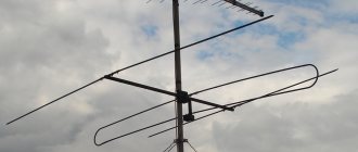
But difficult does not mean “impossible”. There is a method that allows you to overcome the uneven diagram and the drop in gain. It is called a log periodic antenna.
The principle of operation of the antenna is largely due to its thoughtful design. Because of this, it has a wide signal reception range with a uniform gain. Coordination with the signal transmission cable to the receiver (often called a feeder) does not cause any problems.
This device received its name because of the properties it is endowed with:
- Logarithmic dependence of the length of versatile and separated vibrators.
- The periodic arrangement of the vibrators - the difference in the distance at which they are located on the main rods is determined by the operating range of the antenna. In this case, the difference in the size and distance of the vibrators from the “tip of the triangle” obeys a geometric progression.
Do-it-yourself log-periodic antenna for receiving Digital TV
Log-periodic antennas are receiving devices operating in any frequency range. They are also called frequency independent due to their capabilities. They are similar in design to wave-type antennas, but operate according to the logarithmic law, hence their name. You can assemble such an antenna for high-quality digital television reception yourself, but first it is better to familiarize yourself with their types.
Types of logarithmic antennas
The type of device does not change its functionality, but only indicates the design features and spatial coverage:
- Flat unidirectional . They are also active directional log-periodic antennas, represented by an ordinary rod on which “antennae” (conductors) are attached symmetrically in antiphase. They are a simple and cheap design, but they only work in a specific direction.
- Flat . Their design is similar to unipolar antennas. The antennae are longer and convex. They operate only in the horizontal plane, but are direction independent.
- Spatial . From the name we can conclude that it receives signals in both planes. It is represented by a complex of wider versions of flat unidirectional antennas.
Having examined the types, you can see that they do not differ in design, the only difference is in the architecture. Therefore, before studying the design of a log-periodic antenna, you can immediately choose which one is more suitable for use.
There are not many options:
- If there is only one tower in the area, there is reliable access to it, and the construction of a second one is not expected, choosing a flat unidirectional antenna will be a profitable solution. Others are also suitable, but they will not give a greater effect, but will require more costs.
- When there are several repeaters in the area, and analogue and digital TV come from different sources, only a flat antenna will help.
- In mountainous areas, a good signal can only be received using a spatial log-periodic antenna, because the other will not cope due to the terrain.
Log-periodic antenna design
A ready-to-use log-periodic antenna externally resembles a whole complex of devices and is many times more complex than a conventional terrestrial receiver, which are sold in TV stores:
- The axial rod (also known as the supporting tubular element, which determines the location of the initial director antenna panel) provides separate power to the right and left antennae. This is necessary for synchronous reception (radiation) of a signal by antennae placed in antiphase.
- A coaxial cable is used as a signal conductor to the TV, which is connected to the beginning of the rod (the top of the device).
- The antennae, from apex to base, maintain strict synchronicity of elongation at each step. The length of each of the last pair of antennae must correspond to the total length of the first pair (Ln = ½ L1).
Making a conductor
You can make the base yourself or buy a ready-made one. In the latter case, the most successful option would be to use delta type devices in a herringbone shape, which replaces the plane of the reflector array. To assemble it yourself, you can use two methods:
- Spike. If you have a welding machine at hand, it is better to weld such a structure. Everything is simple here, except that it’s better to solder the rods, and only then cut them to the required length.
- Assembly. The antennae can be prepared in advance and secured with copper wire. To attach them firmly to the rod, you will need to fix the entire structure to the board. This will compromise the aesthetics of the finished receiver, but will increase reliability in rain or sleet.
At least one reflex vibrator lying in a plane is used. But it is more practical to take two - on each side of the conductors on the rod. Power is supplied to the top (from the side of the short conductors).
Antenna assembly
Below are the parameters for a log periodic antenna with a power of 10 dB. In the future, it will serve as a standard for the assembly of more other types of devices:
- length of rods (bearing) 160 cm;
- number of antennae - 9 pairs;
- the coefficient of reduction in the length of the next pair of antennae from the base (also known as the coefficient of geometric progression) is 16 cm;
- difference between input and output resistance
20 Ohms (usually 98 and 75 Ohms respectively).
The output will be a log-periodic antenna UHF 460 - 790 MHz. There are also all-wave antennas, which refer to television antennas in the meter and decimeter range.
The carriers must be fixed together (not fastened!) and the last stage of assembly must be completed - grounding. An ordinary 2 mm copper wire is suitable. Before connecting, you need to ensure that the grounding does not conflict with the cable. The rods will be connected by a common contact, and the grounding cable will be routed between them.
Prefab Setup
The log-periodic antenna is ready and all that remains is to configure it. To do this, you need to take both load-bearing tubular elements and move them in close proximity to each other. In this case, the antennae must be exactly parallel to each other. The point is that with a large distance between them (more than 2 cm), the coverage expands, but at the same time weakens, so initially there may not be an image.
When the tower is 20+ km away, you need an antenna with a power of 15+ dB. In this case, the distance between the carriers will be less than 0.8 cm. In most cases, it is enough to check the antenna at a height of 2 m and in a horizontal position. In densely built conditions, the signal will not necessarily come from the tower; you need to try to look at an angle. When a successful relationship is found, the supporting rods need to be secured. A self-made log-periodic flat unidirectional antenna is ready.
Manufacturing of flat and spatial antennas based on unidirectional
To obtain a conventional flat antenna operating over the entire radius of the horizon, you need to make a similar design that will replicate the finished one. They are installed symmetrically to each other with the base. The power wire is bifurcated and connected to both structures, and the cable to one of them by default (but always to the carrier to which power is not connected).
If a spatial antenna is needed, it can also be made according to the finished invention, with a recalculation of their number. You will need three structures that need to be assembled in the shape of a triangular pyramid with a base of antenna vertices. It is installed only on the roof in a vertical position. A copper cable is drawn from each of them, which is assembled into a single complex and connected to the electrical network.
conclusions
Homemade UHF television antennas work on the same principle as factory ones. In particular, it can be strengthened by reducing the shortening of each subsequent pair of conductors. However, to satisfy the condition Ln = ½ L1, more pairs of antennae will be required, and the structure itself will increase in length several times. But the most important thing is that as the signal reception range increases, the frequency range will also shift, as a result of which the receiver will only be able to receive meter waves. Therefore, you can only make an outdoor log-periodic antenna yourself, and if you are very far from the tower, you will need to buy an amplifier.
In general, if you are within 50 km of the repeater, with such an antenna you can receive a reliable digital and analogue broadcasting signal.
What does it consist of?
The log-periodic antenna for digital TV has:
- There are 2 rods on which vibrators are attached. They are made hollow in order to let the cable inside. It is wound through the lower rod, goes in a loop from above and ends with a short-circuited jumper. This must be done for matching and balancing, since there is no need to use an additional circuit in the antenna.
- Vibrators are conductors of various lengths attached perpendicular to the rods, connected by reversing the polarity of the power points.
In fact, the antenna can also catch the MV range. To do this, you just need a longer antenna with longer vibrators. It is difficult to make a structure with rods extended over several meters, since the end vibrators will be too long and the structure will become unstable.
The design of a digital television antenna consists of 2 rods aimed at the source of transmitted signals and vibrators of different lengths placed perpendicularly.
Important properties of the antenna are:
- The denominator of the geometric progression, indicating the rate of decrease of long vibrators from the base of the rod to its end. The lower the indicator, the more efficient the antenna can be considered. Unfortunately, to increase this figure, the size and weight of the device increases.
- The angle at the base of the triangle that the assembled vibrators form. The smaller it is, the better the antenna works. But again, this increases the length of the antenna, increasing the risks of instability and deformation.
Separately, polarization needs to be mentioned. The polarization of waves directly depends on the type of antenna and its location. For example:
- a vertically placed asymmetrical vibrator is vertical polarization;
- horizontally placed vibrator – horizontal polarization.
Log-periodic antenna design
The design of a log-periodic antenna is strikingly complex. Let's try to describe the device. Let's start in a simplified manner, avoiding confusing readers.
- The rod resembles a wave channel traverse and provides separate power to the left and right vibrators. They are symmetrically in antiphase.
- Moreover, the left-right row of vibrators alternates with the carrier (two, closely spaced and parallel). For example, the first left vibrator belongs to the upper carrier, the first right - to the lower one. With the second it is the other way around. The left one is now on the bottom, the right one is on the top.
- The number of vibrators depends on the design, the length of the largest (housed at the rear) is (in total left and right) half the wavelength of the lowest frequency range.
- Power is supplied to the front. It is permissible to make it with a wire laid inside the carrier, or immediately attach a symmetrical line to the top. Let us explain in the first case: the coaxial cable lies inside one guide, and one part of the line will serve as a guide. When leaving the spout, the central core is connected to the second carrier. It turns out that the two-wire line plays the role of a quarter-wave balun transformer.
- The line is shorted behind the longest vibrator at a distance of an eighth of the wavelength of the lower frequency range. According to some information, this was done for coordination reasons. By the way, the good thing about this method is that the vibrators are closed to the ground, therefore, when a lightning strikes, the cable braid will burn first (in the absence of a lightning rod).
How to make a decimeter antenna with your own hands?
Despite the rapid development of satellite and cable television, the reception of terrestrial television broadcasts still remains relevant, for example, for places of seasonal residence. It is not at all necessary to buy a finished product for this purpose; a home UHF antenna can be assembled with your own hands. Before moving on to considering the designs, we will briefly explain why this particular range of the television signal was chosen.
Why DMV?
There are two good reasons to choose designs of this type:
- The thing is that most channels are broadcast in this range, since the design of repeaters is simplified, and this makes it possible to install a larger number of unattended low-power transmitters and thereby expand the coverage area.
- This range is selected for digital broadcasting.
Indoor TV antenna “Rhombus”
This simple, but at the same time, reliable design was one of the most common in the heyday of on-air television broadcasting.
Rice. 1. The simplest homemade Z-antenna, known under the names: “Rhombus”, “Square” and “People’s Zigzag”
As can be seen from the sketch (B Fig. 1), the device is a simplified version of the classic zigzag (Z-design). To increase sensitivity, it is recommended to equip it with capacitive inserts (“1” and “2”), as well as a reflector (“A” in Fig. 1). If the signal level is quite acceptable, this is not necessary.
The material you can use is aluminum, copper, and brass tubes or strips 10-15 mm wide. If you plan to install the structure outdoors, it is better to abandon aluminum, since it is susceptible to corrosion. Capacitive inserts are made of foil, tin or metal mesh. After installation, they are soldered along the circuit.
The cable is laid as shown in the figure, namely: it did not have sharp bends and did not leave the side insert.
UHF antenna with amplifier
In places where a powerful relay tower is not located in relative proximity, you can raise the signal level to an acceptable value using an amplifier. Below is a schematic diagram of a device that can be used with almost any antenna.
Rice. 2. Antenna amplifier circuit for the UHF range
List of elements:
- Resistors: R1 – 150 kOhm; R2 – 1 kOhm; R3 – 680 Ohm; R4 – 75 kOhm.
- Capacitors: C1 – 3.3 pF; C2 – 15 pF; C3 – 6800 pF; C4, C5, C6 – 100 pF.
- Transistors: VT1, VT2 – GT311D (can be replaced with: KT3101, KT3115 and KT3132).
Inductance: L1 - is a frameless coil with a diameter of 4 mm, wound with copper wire Ø 0.8 mm (2.5 turns must be made); L2 and L3 are high-frequency chokes 25 µH and 100 µH, respectively.
If the circuit is assembled correctly, we will get an amplifier with the following characteristics:
- bandwidth from 470 to 790 MHz;
- gain and noise factors – 30 and 3 dB, respectively;
- the value of the output and input resistance of the device corresponds to the RG6 cable – 75 Ohm;
- the device consumes about 12-14 mA.
Let's pay attention to the method of power supply; it is carried out directly through the cable.
This amplifier can work with the simplest designs made from improvised means.
Indoor antenna made from beer cans
Despite the unusual design, it is quite functional, since it is a classic dipole, especially since the dimensions of a standard can are perfectly suitable for the arms of a decimeter range vibrator. If the device is installed in a room, then in this case it is not even necessary to coordinate with the cable, provided that it is not longer than two meters.
Indoor antenna design based on beer cans
Designations:
- A - two cans with a volume of 500 mg (if you take tin and not aluminum, you can solder the cable instead of using self-tapping screws).
- B – places where the cable shielding is attached.
- C – central vein.
- D – place of attachment of the central core
- E – cable coming from the TV.
The arms of this exotic dipole must be mounted on a holder made of any insulating material. As such, you can use improvised things, for example, a plastic clothes hanger, a mop bar or a piece of wooden beam of appropriate size. The distance between the shoulders is from 1 to 8 cm (selected empirically).
The main advantages of the design are fast production (10 - 20 minutes) and quite acceptable picture quality, provided there is sufficient signal power.
Making an antenna from copper wire
There is a design that is much simpler than the previous version, which only requires a piece of copper wire. We are talking about a narrow band loop antenna. This solution has undoubted advantages, since in addition to its main purpose, the device plays the role of a selective filter that reduces interference, which allows you to confidently receive a signal.
Fig.4. A simple UHF loop antenna for receiving digital TV
For this design, you need to calculate the length of the loop; to do this, you need to find out the frequency of the “digit” for your region. For example, in St. Petersburg it is broadcast on 586 and 666 MHz. The calculation formula will be as follows: LR = 300/f, where LR is the length of the loop (the result is presented in meters), and f is the average frequency range, for St. Petersburg this value will be 626 (the sum of 586 and 666 divided by 2). Now we calculate LR, 300/626 = 0.48, which means the length of the loop should be 48 centimeters.
If you take a thick RG-6 cable with braided foil, it can be used instead of copper wire to make a loop.
Now let's tell you how the structure is assembled:
- A piece of copper wire (or RG6 cable) with a length equal to LR is measured and cut.
- A loop of suitable diameter is folded, after which a cable leading to the receiver is soldered to its ends. If RG6 is used instead of copper wire, then the insulation from its ends is first removed, approximately 1-1.5 cm (the central core does not need to be cleaned, it is not involved in the process).
- The loop is installed on the stand.
- The F connector (plug) is screwed onto the cable to the receiver.
Note that despite the simplicity of the design, it is most effective for receiving “digits”, provided that the calculations are carried out correctly.
Do-it-yourself MV and UHF indoor antenna
If, in addition to UHF, there is a desire to receive MF, you can assemble a simple multiwave oven, its drawing with dimensions is presented below.
Indoor multiwave (MV and UHF) antenna
To amplify the signal, this design uses a ready-made SWA 9 unit; if you have problems purchasing it, you can use a home-made device, the diagram of which was shown above (see Fig. 2).
It is important to maintain the angle between the petals; going beyond the specified range significantly affects the quality of the “picture”.
Despite the fact that such a device is much simpler than a log-periodic design with a wave channel, it nevertheless shows good results if the signal is of sufficient power.
DIY figure eight antenna for digital TV
Let's consider another common design option for receiving “digits”. It is based on the classic scheme for the UHF range, which, because of its shape, is called “Figure Eight” or “Zigzag”.
Rice. 6. Sketch and implementation of the digital eight
Design dimensions:
- outer sides of the diamond (A) – 140 mm;
- internal sides (B) – 130 mm;
- distance to the reflector (C) – from 110 to 130 mm;
- width (D) – 300 mm;
- the pitch between the rods (E) is from 8 to 25 mm.
The cable connection location is at points 1 and 2. The material requirements are the same as for the “Rhombus” design, which was described at the beginning of the article.
Homemade antenna for DBT T2
Actually, all of the examples listed above are capable of receiving DBT T2, but for variety we will present a sketch of another design, popularly called “Butterfly”.
Decimeter antenna "Butterfly"
The material can be used as plates made of copper, brass, aluminum or duralumin. If the structure is planned to be installed outdoors, then the last two options are not suitable.
Antenna for an old TV
For modern and old TVs, the reception principle is absolutely the same and the antennas for them are no different. The only difference is the presence or absence of a built-in T2 decoder.
Even a carefully made antenna will not allow you to view digital terrestrial television if there is no set-top box or built-in decoder to decode the digital signal. With a digital tuner (set-top box), even using an antenna of the simplest design made from beer cans, you can receive a digital signal for free in a private home, country house or apartment on a TV of any year.
In areas where the signal is weak, in order to show it well, it is advisable to supplement the device with a power amplifier. A powerful antenna can be used on 2 TVs, and if they are modern, they can be used without a set-top box.
Now you know how to make an antenna for digital TV with your own hands. We hope our instructions with calculations helped you make a suitable option for your conditions!
Published: 02/07/2020 Updated: 02/07/2020
Requirements for a digital packet television antenna
Television towers transmit signals over short distances. Often the length of the electromagnetic wave does not exceed 60 km. In this case, the pulse must have a stable voltage, which, having reached the end of the wave, should not decrease, otherwise you cannot count on a high-quality image of the signal on the TV screen. In this case, it is necessary to take into account the difference between the two potentials of the beginning and end. It is this indicator that creates currents with minimal amplitudes. This parameter entails a list of important requirements that an antenna that receives a “digital” signal must have:
We advise you to study Antenna for a router- When producing independently, it is worth considering that the design of the antenna as a digital receiver must be as accurate as possible. No unnecessary branches, damage, twists or nicks are allowed. These little things can significantly affect the quality of the received signal.
- When installing the antenna yourself, you must direct it strictly according to the polarization, as well as in the direction of the electromagnetic pulses coming from the distribution substation or tower.
- Keep it protected from extraneous signals. Limit the penetration of waves from radios, electric generators, satellite TV to the digital antenna. This will cause interference and the image will be lost.
By adhering to the requirements for a digital television antenna, you will create an impeccable signal for your TV
