Some tips
If this is your first time assembling a box, then be extremely careful and follow our recommendations on how to assemble a 220V electrical panel in a private house. Choose only high-quality machines, plugs, connectors, cables. Do not skimp on electrical wiring - your life, safety and comfort depend on it.
- Duplicate the previously drawn diagram. Hide one in a safe place (for example, in a house register), and stick the second on the door of the shield. In a year or two, you will completely forget how and what is connected to the box, so if repairs are necessary, you will have to call everything again and waste time on it. The diagram will show you all the connections in detail. It will also be useful if you are not the one doing the wiring.
- Place a sticker on each machine, indicating what it is responsible for. For example, “kitchen light” or “hall outlet”.
- Combine the groups of wires included in the box according to a common characteristic and label them.
- After connecting the voltage, watch the shield. Even if everything went well at first, after an hour or two, try the machines and cables by hand to see if they are overheating. Heating indicates that the current is too high.
And lastly, periodically look inside to determine if corrosion has begun and if dust and cobwebs need to be removed. Remember that dust conducts current. By following our instructions, you can quickly and accurately assemble an electrical panel with your own hands. .
We recommend creating a diagram not only for connecting wires to the box, but also for the location of all cables in the apartment (a room-by-room application is made with reference to constants). This will help you when making future repairs or locating a burnt cable.
1+
General information about electricians in the electrical panel
Among what will be required for improvement is the selection of elements, installation and disconnection of cables in the electrical panel. I would like to immediately note that to perform such work you need special knowledge and practical skills in electrical engineering. But if you have instructions, ready-made diagrams, an electrical panel and you know all the safety requirements, you can assemble the panel and figure out how to connect the cable cores yourself.
Electrical panel - what is it for?
The distribution panel that is familiar to us, which is installed at the entrance to a private house or apartment, is needed in order to ensure safety when using electrical equipment and devices. In houses of a new type, such panels are already provided, but even in old buildings they are gradually replacing traffic jams and meters. Using a shield, you can intelligently distribute energy between all groups of consumers and create excellent protection against short circuits and overloads.
For placement you will need a plastic or metal box. First, they install an electric meter and a general switch to completely cut off power to the apartment. This shutdown can be done manually, or it will work itself in an emergency (network overload). If an input machine is installed in front of the meter, then it must be sealed (and the meter too).
Of the group of devices, circuit breakers have the most number of devices. They not only protect the wiring, but also the household appliances themselves. For each machine, a group of consumers is defined, and for each powerful device they install their own machine. Thus, you can turn off the devices individually, or the switch will work automatically in the event of an emergency.
In addition to automatic machines, residual current devices are also installed in the panel. They are needed to compare outgoing and incoming currents and are triggered if the balance is upset. This usually happens due to uncontrolled current leaks, and shutdown occurs due to exposure to current that is safe for humans.
And lastly, there are special busbars in the distribution panel, which are made in the form of copper strips. You can connect machines and other devices to them. The neutral wires go to a special block with terminals - the zero bus. To connect grounding, use a grounding bus.
Consumers and their distribution
All electricity supplied to the facility must be evenly and correctly distributed among all consumers.
When distributing and disconnecting cable cores, you must be guided by special rules and regulations:
- Consumers that are considered powerful (from 2,000 W and more) are grouped into different groups. Each group should be connected to a machine that can withstand the load.
- Connect the washing machine and dishwasher, as well as air conditioning and other devices that are not very powerful, to 16 A machines. Please note that the cable cross-section should not be less than 2.5 mm2.
- Powerful devices (over 380 V) must be connected to 20 Am or 32 Am circuit breakers. In this case, the cable cross-section must be at least 4 mm2. The cable should not have branches, and it should be laid in whole pieces.
- Connect separate lines to the sockets for each room and, if using a three-core cable, the cross-section of which will be at least 2.5 mm2. Separate branches are provided for sockets in the distribution box.
- Lighting devices are also divided into groups and connected to a separate cable, which has a cross-section of 1.5 mm2 and to a 10 Ampere circuit breaker.
Only at first glance, connecting with cable lines seems like an unnecessary and unnecessary stage of work. The best option is a single-line diagram. It received a self-explanatory name due to the group display of wires. Standard diagrams indicate all the wires that belong to each line. The difference between a single-line diagram is that the total number of conductors is depicted with oblique dashes. At the bottom of the diagram there is a special layout with consumer lines, as well as general markings of power and cable that will be used for installation.
Each device is identified by symbols. H1 is a load switch (switch), with which you can open an electrical circuit that is under load. A circuit breaker can be used instead of this switch, but due to its technical characteristics it does not tolerate switching off under load. The remaining symbols H2, H3 and others correspond to the circuit breaker, and the symbols A1, F2, F3 refer to residual current devices.
For clarity, there are diagrams that show devices and equipment, as well as the connections between them. Near each device you can find marks and denominations.
Final installation of the electrical panel. Connecting consumer groups
Pre-assembly and testing work allow you to install the electrical panel by placing it in a prepared niche, hanging it externally, and connecting groups of consumers. You should wait until finishing work is completed, which may contaminate the device, increase the humidity around it, or get it wet.
The procedure is as follows:
- Secure the installation process by excluding the supply of current to the equipment input. In an apartment building, it is worth hanging a special sign on the control panel or the distributor on the floor.
- Remove the protective cardboard or special cover, remove all contents from the box, take the wires out and secure them, and clean the case if necessary.
- Insert the DIN rails with installed modules inside, secure with screws or clamps.
- The protective and working zero busbars are mounted in standard places and insulated in a metal box.
- Zero protective, neutral and phase wires are divided into separate bundles, fixed with plastic clips, and the presence of markings is checked.
- The protective zero cables are attached to the PE bus; the additional length of the reserve is tightened with couplings.
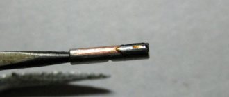
- After entering, all groups of consumers from the protective bundle are connected in series, the ends of the multi-core wires are crimped with the NShVI tip, the rest are stripped with a stripper to 1 cm, the excess is cut off.
- Final marking before clamping into terminals using heat shrink tubing or cable markers.
- The metal door is connected with a green-yellow cable to the protective zero bus.
- Cables connected to the buses of group RCDs are separated from the working zero bundle and brought out into a separate bundle. They are connected to the appropriate bus with a right angle bend, they are stripped, marked and fastened as in the previous group.
- The location of the phase cables should be on the opposite side of the box from the zero side. If there are special niches in the box, they are inserted and secured, branches and bundles of wires are secured with ties.
- In accordance with the diagram, the necessary cables are inserted into each circuit breaker. Marked and trimmed as necessary, secured.
- The working zero and input phase are connected to an automatic switch or input load switch to the upper terminals.
- The correct installation and cable markings are checked according to the working diagram, and all terminals are tightened with a force of 0.8 Nm.
Commissioning works
After completing all the manipulations for assembling and installing the electrical panel, you should put the switches in the “Off” mode and proceed to the final stage - commissioning.
Instructions for testing and debugging:
- The check is carried out after complete installation of lamps, switches, sockets and other electrical installation devices, connections on all dedicated load lines in sockets.
- Voltage is applied to the input of the electrical probe, the presence and value are checked with a multimeter, the correspondence of zero and phase.
- All differential circuit breakers and RCDs are connected in series, with the functionality checked by clicking on “Test”, after which they are turned on again.
- All terminals of automatic switches are checked with a multimeter to determine the presence of voltage at the input.
- The circuit breakers are switched on in series and the output terminals are checked for voltage;
- When electrical appliances are switched on sequentially, the operation of the switchboard is monitored for each consumer line, and the absence of smoke, heating of modules, and sparking is recorded. Otherwise, the problem is found and eliminated.
- Each outlet line is checked for the size and presence of voltage.
- The performance of lighting lines is tested.
- Leave the shield open for several hours and check its functioning.
If the test is successful, all internal parts of the electrical panel should be closed. Colored stickers with markings and identification of each switch should be placed on the surface of the cover or plastron.
To protect the inscriptions, it is sealed with transparent film or tape. In the case of an opaque door, the device diagram should be placed inside it, pasted on tape or placed in special clips (provided in some models).
Drawing up a wiring diagram
It is possible to calculate the dimensions of an apartment or street panel and decide on the choice of protective devices only after drawing up a schematic or installation diagram for the energy supply of the house.
The main thing is to indicate all electrical appliances, lighting equipment and electrical installation devices, as well as their power, voltage and current.
After preparing the wiring diagram, it is necessary to divide all the circuits into separate groups.
To do this, you need to follow the principles:
Now they are producing very powerful equipment, so you should not rely on universal advice; it is better to first study the installation requirements. For example, for some ovens the conductor cross-section must be at least 4 mm², and for water heaters - even 6 mm². Accordingly, machines with 20 or 32 A will be required.
Taking into account the above, a diagram for assembling the electrical panel is drawn up.
Installation of an RCD is mandatory, since without it the protection of outlet lines is considered incomplete. The same can be said about dedicated power circuits for powerful equipment - each device requires its own disconnect device.
Equipment ratings: rated current - one step higher than that of the connected machine, differential operating current - 30 mA.
All circuits related to a bathroom or bathroom are connected to an RCD with a differential. current 10 mA. This may include separate lines for heated floors, washing machines, sockets, and shower stalls.
Step-by-step installation instructions
Let's look at how to make lighting in the garage. Conducting electricity and installing cables, sockets, switches, light sources is not so difficult; you can do it yourself, following step-by-step instructions, observing safety rules when working with equipment and electricity. You definitely need to read the recommendations and listen at least 65-70 percent, because all the advice is taken from examples and cases in real life.
- Before making lighting in the garage, as a preparatory work, it is necessary to draw a clear diagram indicating power sources, lighting fixtures, electrical appliances, wire routes, location of entry points of sockets and switches. This representation will help to find shortcomings at the design stage, when there is still an opportunity to correct them. It will help you buy everything, figure out what you need, without forgetting to buy anything.
- Buy the necessary materials, tools, and equipment from electrical stores.
- Place the purchased devices as indicated in the diagram.
- Install the junction box. There is a separate block for each switch and socket.
- Run a cable to each light source, outlet and to the main electrical panel.
- The junction box should be unsoldered.
- Perform a test run to find faults and shortcomings.
- Eliminate any defects and defects found and retest.
- Engage in decorative finishing of the room.
If electricity is not supplied, then you need to select a power source and connect it instead of the electrical panel. To organize your own autonomous electricity, you will need to purchase:
- Battery - capacity more than 1000 A/h.
- Inverter.
- Charger.
- Generator - power more than 7 W.
A cheaper option is only suitable for organizing a power source for local lighting:
- gas generator - power about 2 kW;
- rechargeable battery - capacity more than 800 A/h.
Step-by-step instruction
The general procedure for installing electrical wiring in a house involves:
- creating a plan for laying wires and placing electrical installation products in rooms;
- laying electrical wires in or on walls and ceilings;
- installation of a switchboard, distribution boxes and sockets with switches;
- switching all this into a single in-house electrical network;
- checking the functionality of the created system and putting it into operation.
There is nothing critically complicated here. The main thing is to choose the right wires so that they can withstand the load without problems, do not forget to install protection devices and carefully connect everything into a single whole.
Circuit markup
Before you start laying electrical wires, you need to mark their wiring on the walls. This is necessary to accurately understand the scope of installation work. Plus, “bottleneck” intersections of electrical wiring and other engineering systems will be immediately visible. For example, if there is a water pipe next to the cable, then something needs to be moved to the side. It is impossible to allow contact, even potential in the future, between water and electricity.
When making markings for electrical wiring, you need to take into account the presence of heating devices, ceiling height, location of windows or doors
According to unspoken rules, when marking electrical wiring, all lines are made strictly vertical or horizontal. This reduces the risk of damage to electrical wires during further finishing and makes them easier to find later during repairs.
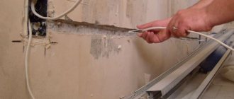
Wall work
After marking has been completed, you can begin drilling and slotting work. But first you need to decide whether the electrical wiring will be laid in an open or closed way. In the first case, there is no need to trench the walls, but the wires will have to be covered somehow with decor. And in the second, they will be completely recessed into the thickness of the ceilings and partitions, but a lot of drilling and hammering will have to be done with a hammer drill.
Open wiring
When laid open, electrical wires are laid in tubes, special baseboards and cable ducts. They are made from fireproof and self-extinguishing plastics. If a private house is made of timber or logs, then you will have to choose this option. Wires cannot be installed inside wood.
Options for laying open electrical wiring
Closed wiring
Closed wiring involves laying cables in a hidden way in cavities inside walls and ceilings. To create such recesses in brick or concrete, you will have to work with a hammer drill and a grinder. There will be a lot of dirt. But then all the wires will be under a layer of plaster, which will make the interior more aesthetically pleasing.
A closed wiring diagram must be designed in the early stages of repairs.
Preparing the wires
Electrical wires are selected based on the power consumption of electrical appliances on a specific line from the switchboard. Typically, all electricity consumers in a cottage are divided into groups with approximately the same load, so that the cross-section of all cables in a private house is the same.
According to the material used to make the wire cores, there are:
The first ones are cheaper, but tough. It is much easier to bend copper and place it in grooves, pipes and channels. According to their design, they can be single-core or multi-core. It is recommended to take two- and three-wire wires for your private cottage (the first for lighting, the second for sockets with grounding).
Types of wires for different circuits
Which ones to choose
You can now buy a wide variety of wires on the market. But for independent installation of electrical wiring, you should choose the option with double insulation VVG or PVG with the additional marking “ng” (does not support combustion). These are the most affordable power cables that are optimally suited for installation in buildings. They are available in stores in all sections. Required cables for the cottage with cores of 2.5, 4 and 6 sq. mm easy to find.
Input cable
The thickest wire in the electrical wiring of a private house will be the input wire, which bears the total load. Electricians from the power supply company now usually install self-supporting insulated wires (SIP) from the pole to the electrical panel. They install this cable themselves, and then they will have to install the introductory line themselves along the adjacent area and cottage.
Wiring installation
Step-by-step instructions for installing wiring in a garage include several points, each of which is dedicated to a separate type of operation. All of them are carried out in a certain sequence and begin with preparatory activities.
The step-by-step plan contains the following mandatory items:
- Marking routes for laying cable harnesses.
- Making grooves (if it is decided to install the electrical wiring in a hidden way in the thickness of the walls).
- Arranging niches for installing sockets and switches.
Indentations when marking the electrical wiring route
From sockets and switches, the route is drawn strictly vertically upward, where a distribution box is installed just under the ceiling. This will allow you to take into account the intended location of the wires in the future and, if drilling is necessary, not to damage them.
If heating pipes are laid in the room, the wiring routes should be located at a distance of no less than 25 cm from them. Places for sockets are planned at a distance of approximately 0.3 meters from the floor, and for switches - about 1.0 meters. At the same time, the removal of wires and installation sites for electrical installation products from door jambs and window frames is maintained (it should not be less than 10-15 cm). Unlike residential apartments, in garages switches are installed near the garage door or gate. The depth of the grooves is selected depending on the thickness of the cable or wire harness (according to the PUE, this figure should not exceed 2.5 cm).
Various fasteners for cable or wire are shown in the photo below:
- Tie clamp, universal fastening element for fixing conductors
- The tie is designed for fastening cables on concrete and brick foundations
- Metal bracket for cable fastening
- Plastic bracket for cable fastening
- Electrical insulator for fastening retro wiring
- Dowel tie for fastening conductor or cable products
- Dowel clamp for fastening flat and round cables
- Homemade fasteners made from steel tape
- Homemade fasteners from pieces of wire
- Plastic clips for fastening a round cable or corrugated pipe
- Plastic cable channel
Input of power cable and installation of electrical panel
If a permanent garage is separate from the house, the power cable is supplied to it through the air (on support poles).
Requirements for the overhead line wiring route and entry into the building.
The requirements for the overhead line wiring route look like this:
- The height of the SIP wires above the roadway is at least 6 meters.
- Their distance from the ground in the pedestrian zone is 3.74 meters.
- The height of the entry point into the garage building is not lower than 2.75 meters.
Overhead and underground power cable entry into the garage box. In cooperative associations, part of the work related to the supply of zero and phase is taken over by the local administration. In this case, the power cable is inserted from a common line from the outer wall of the garage boxes.
Connecting the metering panel to the power line and entering the power supply to the garage room, watch the video:
The switching elements of the input device are located in an electrical panel hung on the wall of the building near the entrance. The cabinet houses the following switching and protective equipment:
- Switch (introductory machine).
- Accounting counter.
- Linear automatic devices.
- RCD and grounding bus.
A homemade or purchased step-down transformer can also be installed here. Electrical panel diagram for a garage with an electric energy meter Electrical panel diagram in a garage without a meter. The electrical panel diagram indicates the brand and type of cable connecting all these elements. There are two options for circuit solutions for garages:
- In the first case, there is no inspection hole in the room.
- In the second version, you will have to install a special transformer that provides 12 or 36 Volt power to a portable lamp and lamps in the inspection hole.
Internal wiring and lighting of the inspection pit
Internal installation of electrical wiring is carried out either hidden (in grooves) or openly - in a metal sleeve, cable duct or corrugation.
The inspection pit must be illuminated with reduced voltage lamps of 12, 24 or 36 volts, depending on the step-down transformer you purchased. LED strips rated at 12 Volts are often used as light sources. In this case, power can be taken from the battery, since the consumption of LED elements is negligible.
Assembly sequence
To install the incoming electrical panel in an apartment or private house, purchase 2-4 meters of colored installation wire grade PV3, PV1 with a cross-section of 4-6 mm²:
- for zero – blue;
- for phase - white, red, brown, black;
- for grounding - yellow-green colors.
To assemble modular equipment, the following consumables are purchased:
- combs;
- end caps;
- cross-modules or zero busbars for RCDs;
- plastic clamps for fixing cables;
- limiters for DIN rails.
Housing installation
Load-bearing walls are not suitable for installation; it is not prohibited to construct a false wall from plasterboard for electrical installation of a built-in panel. The location must meet the requirements:
- availability of free access;
- from the edge of the box to the slope, jamb, corner of at least 15 cm;
- There are no gas pipes nearby.
Comment!
The air humidity level in the room where the electrical panel is located is not higher than 60%.
Sequence of actions when installing the shield:
- Having retreated 1.4 m from the floor, using a level, draw 2 lines - the bottom horizontal and one vertical;
- apply the body to the markings and outline it around the perimeter;
- using a grinder, make cuts at least 9 cm deep;
- a cavity is hollowed out using a perforator;
- fastening elements are mounted on the rear wall of the case;
- Mark the holes in the cavity and drill them with a hammer drill;
- drive in dowels;
- fasten the box to dowel-nails.
The gaps between the walls of the niche and the box are filled with concrete, other building mixture or polyurethane foam.
Cable entry
High-quality panels have technological holes for entering cables with a diameter of 16-20 mm under a standard-sized corrugated pipe; in low-grade products they are drilled or sawed out.
When connecting an electrical panel installed in a niche, perform the following manipulations:
- remove the plugs or squeeze out the stuffing box plates;
- the input cable is inserted into the technological hole of the box, it is placed close to the input machine;
- apply it to the comb, fix it with a plastic clamp, remove excess tie with wire cutters;
- mark the cable in accordance with the diagram;
- the remaining cables are inserted and labeled in the same sequence;
- attach a removable cover to the box, mark the entry points of the cores with a marker;
- Use the blade of a construction knife to cut holes.
The electrical panel plug is put in place, after which it is necessary to assemble and switch the modular devices.
Cabling
Each cable is marked as in the diagram, the insulation layer is removed without damaging the conductors. To ensure that there is enough length, two heights of the box are measured from the insertion point. When routing wires in the panel, make sure that insulating materials do not get into the terminal contacts. Do not connect wires of different sections to one machine.
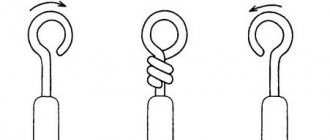
For better contact, the end of the wire is bent in the form of the English letter “U”. For switching multi-core wires, lugs are used:
- NSHV;
- NSHVI.
Special devices ensure reliable contact.
Shield installation
It is not difficult for a person who has basic knowledge of electrical engineering to assemble a single-phase panel with automatic circuit breakers. First, all modules are secured with clamps to the first DIN rail exactly according to the diagram:
- switch;
- UZM;
- RCD (by number of consumer groups);
- differential machine.
Comment!
To prevent modules from moving on the DIN rail, limiters are installed.
The machines are installed on the second DIN rail, each with its own RCD, starting from the right side. To power equipment (automatic devices, RCDs), combs are used. Wiring sequence:
- switch and UZM;
- UZM and the first RCD;
- each RCD with its own zero bus, it is installed in the lower part of the box;
- The machines are connected to the RCD.
After assembly, the shield is installed in place, the input cable and load wires are connected.
Connecting consumers
Disconnect the input cable coming from the control panel (access panel). The wires are distributed into three bundles:
- L - phase;
- N – zero workers;
- PE – zero protective.
Comment!
After connecting the input cable to the switch (input circuit breaker), the meter and circuit breaker terminals are sealed by the inspector of the energy supply organization.
The sequence of connecting the protective zero wires to the PE bus:
- input core for the large terminal;
- cables from consumer groups;
- metal parts of the box (body, door).
One part of the cores of the working zero is connected to the zero busbars of the RCD, the second part to the central zero busbar. The phase conductors are crimped and clamped with machine terminals. The last thing to connect is the input cable.
Studying the box wiring diagram
When connecting wires in a junction box, it is very important to know the specific markings of each cable. This will create a secure, reliable and generally correct connection.
Let's study the wiring diagram of the box. Connecting wires with grounding (PE)
Connecting wires without grounding (PE)
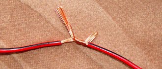
So, the “zero” wires (in the diagram they are blue) and the ground cables (indicated in yellow) are connected accordingly by color, as shown in the image. When arranging two-wire wiring, the circuit remains the same, only the grounding wires are excluded.
The phase desoldering procedure (indicated in black or red) is more complex. If only cables are routed through the box to connect the socket, the phase wires are also connected together.
Scheme in a junction box, two lamps
If cables go from the box to a switch with one button, then the wire that goes to the switch must be twisted with all the wires of the phase. The same cable that comes from the switch is connected to the phase wire going to the lighting fixture. As a result, 4 connections will be made.
Scheme in a junction box, two lamps and a group of sockets
In the case of connection through a junction box of a switch with two keys in conditions of three-wire wiring, a cable with four cores is connected to the chandelier. If the wiring is two-wire, the number of wires is reduced to three, because grounding is excluded from the circuit, as shown in the figure.
Studying the box wiring diagram
Without taking into account the separate twisting of the ground electrode, 4 connections are created in the box. All the “zero” wires (indicated in blue) are connected to each other.
The phases of the sockets and the power cable are twisted together and then connected to the common terminal of the switch with two keys. From the latter there are 2 separate wires going to the lighting fixture.
Thus, there is nothing super complicated about wiring the box. You just need to understand the peculiarities of the wire designation and the order of their connection. After this, you can begin to consolidate the acquired theoretical knowledge in practice.
Proper connection of wires in the junction box
Prices for distribution boxes
Distribution boxes
Drawing up a diagram
Modern power supply systems involve the use of a three-wire cable, where one wire is a phase, and the rest are ground and zero. Given the growing power of devices, it is also necessary to divide them into groups, which allows to increase the service life of the wiring. Guided by these principles, we proceed to drawing up a diagram of the shield.
It is mandatory to install a protection device on the input cable, which will protect the internal network from overvoltage. Then they install a voltage relay to control surges in the network, after which they proceed to the installation of groups and individual lines. It is worth noting that for powerful devices, in addition to switches, additional RCDs or differential circuit breakers are used. Such organization of the home electrical network is not only safe, but also convenient. If necessary, you can turn off the machine and turn off the washing machine. You can also turn off the RCD and de-energize all consumers included in the global group.
Drawing up an electrical panel diagram
At the next stage, you can proceed to drawing up a diagram. The most optimal would be a single-line option. This circuit got its name because of the group display of wires. On conventional diagrams, all the wires associated with each line are drawn. On a single-line diagram, the number of conductors in groups is depicted by inclined transverse lines. At the bottom there is a layout with consumer lines, indicating their power and cables used for installation.
All devices are identified by special symbols. H1 is a load switch or switch that opens the electrical circuit under load. Instead, it is possible to use a circuit breaker, but it does not tolerate switching off under load due to its technical characteristics. H2, H3, H4... etc. correspond to circuit breakers, symbols A1, F1, F2, F3 – residual current devices.