4.1. Requirements for the functional characteristics and design of RCD-D
4.1.1. The functional characteristics of the RCD-D must comply with the requirements set out in GOST R 50807-95.
Note.
The values of the functional characteristics of the RCD-D are given in Appendix 1.
4.1.2. RCD-D should not automatically re-close.
The verification is carried out by testing according to clause 5.3.
4.1.3. RCD-D should not automatically disconnect the consumer from the network when the network voltage is removed.
The verification is carried out by testing according to clause 5.4.
4.1.4. RCD-D should not have an autonomous auxiliary power source.
4.1.5. The maximum shutdown time of the RCD-D should be no more than 0.5 s.
The verification is carried out by testing according to clause 5.5.
4.1.6. The RCD-D must remain operational at a network voltage ranging from 0.6 to 1.2 of its rated voltage.
The verification is carried out by testing according to clause 5.5.
4.1.7. RCD-D must remain operational after reaching an ambient temperature of 100 °C.
The verification is carried out by testing according to clause 5.6.
4.1.8. The response current of the RCD-D to prevent fires from electrical installations, as a rule, should not exceed 0.3 A. It is allowed to increase the response current to 0.5 A when installing the RCD-D at the head sections of a branched electrical network or to ensure selectivity of series-connected devices.
The verification is carried out by testing according to clause 5.5.
4.1.9. RCD-D should not operate when exposed to impulse noise in accordance with the requirements of GOST 50007.
When tested, the degree of rigidity should be equal to 1.
4.1.10. Nominal values of environmental climatic factors in accordance with GOST 15150. The type of climatic modification must be indicated in the technical specifications for a specific product.
4.1.11. RCD-D should be manufactured with one value of the rated differential tripping current or with a multi-position setting of the differential tripping current with discrete fixed values.
4.1.12. Based on the number of poles, two-pole and four-pole RCDs are recommended.
4.1.13. The RCD-D without built-in overcurrent protection must be protected from short circuits by connecting circuit breakers or fuses in series. In this case, the rated current of the circuit breakers should not exceed the rated current of the RCD-D.
4.1.14 The design of the RCD-D must provide for the possibility of sealing the covers. The element for adjusting the RCD-D setting must be located so that access to it is possible only after opening the seal.
4.1.15. The design of the RCD-D must exclude the possibility of changing its operating characteristics by external influence, with the exception of specially provided means for changing the differential operating current setting.
4.1.16. The RCD-D must be equipped with indicators of the closed and open position of the main circuit contacts. If a light indicator is used to indicate the position of the contacts, it should glow when the RCD-D is on and be of a bright color. The indicator light cannot be the only means of indicating the on position.
4.1.17. The RCD-D must have clamps designed for connection to fixed wiring, in which the connection is made using screws, nuts and similar effective means.
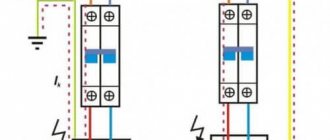
4.1.18. The RCD-D body must contain a diagram of its connection to the electrical network.
4.1.19. Air gaps and creepage distances must not be less than the values indicated in the table. 1.
The inspection is carried out by testing in accordance with GOST R 50345.
Table 1
| Name | Value, mm |
| Air gaps | |
| 1. Between live parts disconnected when the RCD-D is open | 3 |
| 2. Between live parts of different poles | 3 |
| 3. Between live parts and: | |
| — metal controls; | 3 |
| - screws and other means of fastening covers, which must be removed when installing the RCD-D; | 3 |
| — the surface on which the base is mounted; | 6 (3) |
| — screws and other means of fastening; | 6 (3) |
| - other available metal parts | 3 |
| Creep distance | |
| 1. Between live parts disconnected when the RCD-D is closed | 3 |
| 2. Between live parts of different poles For RCD-D with a rated voltage of no more than 250 V | 43 |
| 3. Between live parts and: | |
| — metal controls; | 3 |
| - accessible metal parts | 3 |
The principle of checking the performance of an RCD
When a material is tested for strength, they try to break it. To test circuit breakers, it is necessary to create conditions under which they will work - all existing tests are carried out according to these rules.
The residual current device trips if it detects a current leak, i.e. when more current is supplied to an electrical circuit through the phase wire than comes out of it through the neutral wire. Connecting an RCD can be done in houses with or without grounding - to carry out checks, you need to understand the difference between these methods of protecting household appliances and people.
- In the first case, if the wiring insulation is broken, then part of the current goes to the body of the electrical appliance, from where it immediately goes to the ground wire, as a result of which a leak occurs, which the residual current device immediately registers and opens the circuit.
- If there is no grounding, then if the insulation is damaged, the current again enters the body of the electrical device, but since it has nowhere else to go, then in general the balance between the input and output is maintained and the RCD does not yet trip. A leak will be detected only if a person touches a faulty electrical appliance - current will flow through the body, the balance between the incoming and outgoing current in the main circuit will be disrupted and the RCD will immediately turn off the power.
Those. a correctly connected and working residual current device will work in any case, but if the network is without grounding, then the fault will be detected only after the person is slightly tickled with electric current (if the device is correctly selected, then even painful sensations should not occur).
Of course, if there is no grounding, then checking the functionality of the RCD by touching the phase wire is, to put it mildly, a very extreme method - if suddenly the device is faulty, then a noticeable electric shock is inevitable.
Despite the difference in connection methods, the operating principle of the residual current device remains unchanged and all methods for testing the device are suitable in both cases. In this case, the installed automatic circuit breaker is checked in exactly the same way, because it is the same RCD, only combined in one housing with a circuit breaker.
4.2. Requirements for electrical insulating and structural plastic materials
4.2.1. The materials from which the external parts of the RCD-D are made (except for decorative elements), as well as those used in the design of electrical connections to support live parts in a certain position, must withstand the ball pressure test.
The verification is carried out by testing according to clause 5.7.1.
4.2.2. The materials from which the RCD-D parts are made must be resistant to the burner flame.
The verification is carried out by testing according to clause 5.7.2.
4.2.3. Insulating materials supporting screw connection structures must be resistant to the effects of thermal energy generated in the transition resistance of a defective contact connection, as well as resistant to the effects of heated wire.
The verification is carried out by testing according to paragraphs. 5.7.3, 5.7.4.
4.2.4. Materials through which it is possible to form a conductive bridge between parts of different polarities and different potentials must be tracking-resistant.
The verification is carried out by testing according to clause 5.7.5.
Note. The requirements set out in clauses 4.2.1 and 4.2.2 do not apply to parts of the RCD-D made of metal and ceramics.
4.4. Requirements for the content of technical documentation
Operational documents (technical description, operating instructions, passport) for RCD-D must contain the following information:
— purpose of the product;
— list of characteristics in accordance with the requirements of GOST R 50807;
— product composition and delivery set;
— device and principle of operation;
- Climatic performance;
— safety and fire safety requirements, number of technical conditions or standard, the requirements of which the RCD-D corresponds to;
— procedure for preparation for work and maintenance;
— storage rules;
- certificate of acceptance;
— full name of the manufacturer, its address;
— certificate of conformity or fire safety, issued by whom, registration number, validity period;
— installation and installation requirements;
— rules for checking technical condition;
— recommended type of circuit breaker for RCD-D without overcurrent protection.
5.1. General requirements and test conditions
5.1.1. Tests in accordance with these standards are mandatory when conducting certification tests of RCD-D for fire hazard.
The list of tests is given in table. 2.
5.1.2. The sample submitted for testing must represent a completed product. Its components or elements, design and manufacturing technology must be the same as those of the product supplied to the consumer.
table 2
| Trial | Item number | |
| Requirement | Test method | |
| 1. Testing of RCD-D for compliance with the requirements for functional characteristics: | ||
| — test for the possibility of automatic restart; | 4.1.2 | 5.3 |
| — testing for the possibility of disconnecting the consumer from the network when the network voltage is removed; | 4.1.3 | 5.4 |
| — test for deviations in the supply voltage of the electrical network: | ||
| a) testing of RCD-D in the absence of load current; | 4.1.5, 4.1.6, 4.1.8 | 5.5.1 |
| b) testing of RCD-D at rated load current; | 4.1.5, 4.1.6, 4.1.8 | 5.5.2 |
| — test at elevated ambient temperatures | 4.1.7 | 5.6 |
| 2. Testing of electrical insulating and structural materials: | ||
| — heat resistance test; | 4.2.1 | 5.7.1 |
| — Bunsen burner flame test; | 4.2.2 | 5.7.2 |
| - hot wire test; | 4.2.3 | 5.7.3 |
| — testing for poor contact using incandescent elements; | 4.2.3 | 5.7.4 |
| — test for resistance to the formation of current-carrying bridges | 4.2.5 | 5.7.5 |
5.1.3. At least three products of the same modification, a set of components and spare parts are submitted for testing.
If product modifications differ only in rated load current, it is allowed to submit for testing an RCD-D with minimum and maximum load current values.
(Changed edition.
Amendment No. 1).
5.1.4. The test is carried out by installing the RCD-D in one of the operating positions provided for in the installation instructions, in which the greatest heating of the product is expected.
UZO-D is attached to a plywood board 20 ± 2 mm thick, painted with matte black paint. The fastening method must comply with the manufacturer's recommendations.
5.1.5. For RCD-Ds that have several differential trip current settings, tests are carried out for each value.
5.1.6. The test is carried out at an ambient temperature of 20 + 5 °C.
5.1.7. RCD-D, designed for installation in individual enclosures, is tested in the smallest of the specified enclosures.
5.1.8. Wires are connected to the RCD-D in accordance with the requirements of GOST R 50807.
5.1.9. The accuracy class of measuring instruments for determining the value of differential leakage current must be at least 0.5.
For devices for measuring shutdown time, the relative error should be no more than 10% of the measured value.
5.1.10. The number of tests according to clause 5.2.1 for each pole must be at least five.
What is an RCD?
The correct name of the RCD is an automatic circuit breaker controlled by differential current.
This switching device serves to automatically interrupt the circuit when the unbalance current that occurs under certain conditions exceeds the established figures. The operation of the internal mechanism of the device is based on the following rules: neutral and phase conductors are connected to the terminals, after which they are compared by current. In the normal state of the entire system, there is no difference between the phase current indicators and the neutral conductor data. Its appearance indicates a leak. Having analyzed the abnormal condition, the device turns off.
The functions performed by the residual current device are not typical for conventional switches. The latter react only to overload or short circuit
To put it in simpler terms, the RCD is triggered and breaks the network when the current begins to flow beyond the electrical wiring or devices connected to the electrical network.
In those circuits in which leaks are possible and the possibility of electric shock to people is very likely, an RCD is most often installed. In a house or apartment, these are places where vapors accumulate, thereby causing increased humidity. This is the kitchen and bathroom. In addition, these rooms are the most saturated with various types of electrical appliances.
The minimum current the flow of which is felt by the human body is 5 mA. At a value of 10 mA, the muscles contract spontaneously and a person cannot independently release a dangerous electrical appliance from his hands. Exposure to 100 mA current is fatal
One of the usual electrical assistants can give a person an electric shock when it is not possible to ground it or this was not taken into account during the design. When the insulation of the leading wires in one of the devices is broken, current will flow to the body of the unit.
If there is no grounding, a person will receive an electric shock when touching such a surface. To prevent this from happening, it is necessary to install a protective shutdown device.
RCD designs may differ in their mode of action. Manufacturers produce devices that have an auxiliary power source for normal operation of the electronic circuit and devices that do without it.
Electromechanical protective devices are triggered directly by leakage current, using the potential of a pre-charged mechanical spring. The operation of RCDs on electronic components is entirely dependent on the presence of voltage in the network. It requires additional power to turn off. In this regard, the latter device is considered less reliable.
5.2. The testing procedure includes two stages
5.2.1. The first stage is testing the RCD-D for compliance with the requirements for functional characteristics.
5.2.2. The second stage is testing electrical insulating and structural materials:
5.2.2.1. Heat resistance test.
5.2.2.2. Bunsen burner flame test.
5.2.2.3. Hot wire test.
5.2.2.4. Poor contact resistance test.
5.2.2.5. Test for resistance to the formation of current-carrying bridges.
5.3. Testing of RCD-D for the possibility of automatic restart
The RCD-D test is carried out with a differential sinusoidal current in the absence of load current, in accordance with GOST R 50807 with the following modification.
The differential current is gradually increased so that from the initial level, a value of no more than 0.2 from the rated value, within 30 ± 2 s it reaches the value at which the shutdown occurs.
Then the current is reduced to the original value within 30 ± 2 s.
In this case, the RCD-D should not switch on again.
The third way to check the RCD is to simulate a current leakage
Theory, as they say, is good, but practice is more interesting. Therefore, in this section we will consider an example of how to test an RCD for operation in a practical way.
This method is the most practical in this article, since to implement it you need to assemble a small circuit. The advantage of this method of checking the RCD is that we will see at what leakage the residual current device actually worked. However, there is a minus: in this experiment there is no way to record the shutdown time.
To implement this experience you will need:
- - a regular 10 W lamp;
- — resistor with a resistance of 2 kOhm;
- - rheostat;
- - ammeter;
- — protective shutdown device;
- - connecting wires.
At first glance, it may not seem clear why such a set of elements is needed. I'll explain everything in order. The point of all the work is to gradually increase the leakage current and see at what value the RCD will turn off. The rheostat serves as the organ with which you can smoothly regulate the current.
But I didn’t have a rheostat, but I did have a dimmer (dimmer), so I used it in the circuit instead of a rheostat. And what? A dimmer is the same rheostat, it also smoothly changes the current, due to which the luminous flux of the lamp changes.
With the help of all these elements, a simple circuit is assembled, similar to what was assembled above (a test lamp with a resistance), only in addition there is a rheostat and an ammeter.
How to check the RCD for operation in this case? All elements are assembled in series and connected at one end to the phase output of the residual current device and the other to the zero input. By gradually increasing the leakage current, it is necessary to fix its value at which the residual current device will operate.
It is not visible in the photo, but the RCD test was successful. The RCD of the VD1-63 series from IEK with a rated differential current of 30 mA tripped with a leakage of 10 mA.
What should I do if pressing the TEST button does not turn off the residual current device?
If the residual current device does not operate when the “Test” button is pressed, then this is evidence of a malfunction of such a device, namely a malfunction of one of its internal mechanisms.
One of those cases when the RCD test does not work is a malfunction of the leakage current simulation mechanism itself. In this case, the RCD can continue to perform its protective function, even despite the existing malfunction.
However, it is still recommended to replace such an RCD, since there is no confidence in its reliable and long-term operation. Human life is still worth more. Moreover, the price for an RCD is not so unapproachable (approximately 600 - 1000 rubles / piece).
If you liked the article, share it with your friends!
5.6. Testing of RCD-D at elevated ambient temperatures
Before starting the test, the RCD-D is kept for 24 hours in an atmosphere having a temperature of 20 ± 5 ° C and a relative air humidity of 45 to 75%.
The test is carried out in a heat chamber in which the temperature is maintained at 100 ± 2 °C.
After 1 hour, the sample is removed from the heat chamber.
During the test, the structural elements of the RCD-D should not be deformed so much that their further use would be impossible. The potting compound must not leak out, exposing live parts.
After cooling the RCD-D to a temperature of 20 ± 5 °C, the operation of the RCD-D is checked when a differential current suddenly appears.
When testing, the RCD-D must operate at a test current equal to 1.25 of the rated differential breaking current.
5.7. Testing of electrical insulating and structural materials
5.7.1. Heat resistance test
Non-metallic and insulating materials are checked by subjecting samples of the corresponding parts of the RCD-D to pressure from a ball in a heat chamber using the device given in Appendix 2.
Before starting the test, the sample is kept for 24 hours in an atmosphere having a temperature of 15 to 35 ° C and a relative humidity of 45 to 75%.
The heat chamber is heated to a temperature:
125 ± 2 °C - for RCD-D parts that hold current-carrying parts in a certain position and support connections in a certain position, as well as used as additional or reinforced insulation;
75 ± 2 °C - for external parts of the RCD-D, not intended for holding current-carrying parts in a given position.
The sample is placed in a heat chamber on a stand so that its upper surface is horizontal. The sample thickness must be at least 2.5 mm; if necessary, the samples are placed on top of each other until the required thickness is achieved.
After this, without removing the sample from the oven, they begin to press on its upper surface with a ball with a diameter of 5 mm with a force of 20 N.
After 1 hour, the device is removed, and the sample is cooled to room temperature by immersing it for 10 s in water, the temperature of which does not exceed the ambient temperature of 20 ± 5 °C. Measure the diameter of the ball imprint, which should not exceed 2 mm.
5.7.2. Bunsen burner flame test
The test procedure is in accordance with GOST 28779 (FH method) with the following addition.
The thickness of the sample should be no more than the thickness of the electrical insulating part of the UZO-D.
The material is considered to have passed the test if for external parts made of non-metallic materials, for parts of the product that hold live parts and support connections in a certain position, the material complies with class FH2, and for other parts made of non-metallic materials - class FH3.
If it is not possible to produce samples of the required dimensions, testing for resistance to the burner flame is not carried out.
5.7.3. Hot wire test
Test procedure in accordance with GOST 27483 (IEC 695-2-1) with the following addition.
The temperature of the wire loop, depending on the purpose of the parts of the product, should be:
960 ± 15 °C - for external parts of the RCD-D, made of insulating materials designed to hold current-carrying parts and parts of the protective circuit in a given position;
650 ± 10 °C - for all other parts of the UZO-D, made of insulating materials.
5.7.4. Poor contact test using incandescent elements
The test procedure is in accordance with GOST 27924 (IEC 695-2-3).
The test is carried out on RCD-D contact connections with a rated current of not more than 63 A.
5.7.5. Test for resistance to the formation of current-carrying bridges
The test procedure is in accordance with GOST 27473 (IEC 112-79) with the following addition.
The test is carried out at a voltage of 250 V for two-pole RCD-D and 400 V for other RCD-D using solution A.
The voltage at which insulating materials are tested is selected taking into account the severity of the operating conditions specified in the technical specifications for products made from these materials in accordance with GOST R IEC 335-1-94.
(Changed edition.
Amendment No. 1).
Checking the RCD using a special test lamp
Almost every person has the opportunity to check and make sure that the device is in technically sound condition, and that its operation is carried out adequately and with a normal level of practical reliability.
As you know, the residual current device starts to turn on in the event of a leakage current. This makes it possible to independently create such a leak using a conventional lamp and resistors.
It is necessary to stock up on some tools to check the RCD, including a piece of electrical wire, an electric lamp (it is best to give preference to an incandescent lamp with a power of about ten W), a socket for an electric lamp, several resistances, an electric tool (screwdriver, side cutters, insulating tape and others).
The first step is to calculate exactly what current flows through the lamp. That is, it is important to understand what leakage current can be created. To calculate the characteristics of the current through the lamp, you can use a formula such as I=P/U. In it, P means the power of a particular lamp, and U represents the network voltage.
For example, if the lamp power is 25 W, then the test differential leakage current will be 114 mA. Of course, testing with a lamp will be quite crude, because there is an RCD rated at 30 mA, and more than 114 mA is passed through it. This is most definitely not the best option.
A lamp with a power of ten W has a resistance of about 5350 Ohms. In this case, a current of approximately 0.43 A will flow through the lamp. This current is large for testing a 30 mA RCD, which is why it is necessary to somehow try to reduce this figure. You can do this by adding resistance. Typically, the technical data sheet states that the residual current device should operate at 30 mA leakage. But in fact, shutdown begins to occur at less significant currents, for example, about 15-25 mA.
For a clear example, you can assemble a circuit where the current will be the same as the differential current indicators for which the RCD is designed. In general, you need to take a circuit with a current indicator of 30 mA. Thanks to the already known formulas from the physics course, you can easily calculate the level of resistance that should be present directly in the circuit: R=U/I = 7700 Ohms.
All this suggests that in order to allow a current of 30 mA to flow through the network, the resistance must be approximately 7.7 kOhm. The lamp resistance is about 5.35 kOhm. You need to add another 2.35 kOhm. This resistance can be purchased at almost every amateur radio store. At the same time, its cost is quite acceptable.
We had several resistors with us, the power of which is 5 W and the resistance is 4.7 kOhm. You can use them. However, if you connect such a resistor in series with a ten-watt lamp, it will certainly burn out, because it is not designed for such a load. It is necessary that the power of the lamp and the resistor match. But when connecting a pair of such resistors to a lamp in parallel, you can get a total power of exactly 10 W. In this case, the resistance in the circuit will be 2.35 kOhm. After this, using wires, it is necessary to connect these resistances in series with the lamp.
PICTURE 3
You also need to know how you can test the RCD for operation using such a device. If the protective zero is connected to the sockets in the house, then you can check the RCD for operation in any of the sockets.
It is necessary to connect one end of the wire of the created device to a phase in the socket, and the other to touch the protective zero. If everything is done correctly, the residual current device should trip.
If the sockets in the house are connected without a special protective zero, and in most cases this is the case, then it will not be possible to check each socket. In this case, it will be possible to check the functionality of the device only in the electrical panel where it is installed. To do this, you need to connect one end of the device to the zero input terminal of the device, and the other end to the phase output.
If a question arises regarding the need to use this light bulb in a circuit, then you need to understand that this is required for clarity. Using a lamp, you can visually observe that there is current. Naturally, it will function only at half the heat, however, despite this, you will be able to see everything with your own eyes, that is, that current passes through it, and there is a leak.
For example, you can remove a light bulb from the circuit. If the resistance is damaged, then it is impossible to understand with the help of vision whether it is working or not. In this case, when checking the functionality of the device, current will not flow past it. Therefore, it is possible to draw an erroneous conclusion regarding the malfunction of the RCD.